Commensurability resonances in two-dimensional magneto-electric lateral superlattices
Abstract
Hybrid lateral superlattices composed of a square array of antidots and a periodic one-dimensional magnetic modulation are prepared in heterostructures. The two-dimensional electron gases exposed to these superlattices are characterized by magnetotransport experiments in vanishing average perpendicular magnetic fields. Despite the absence of closed orbits, the diagonal magnetoresistivity in the direction perpendicular to the magnetic modulation shows pronounced classical resonances. They are located at magnetic fields where snake trajectories exist which are quasi-commensurate with the antidot lattice. The diagonal magnetoresistivity in the direction of the magnetic modulation increases sharply above a threshold magnetic field and shows no fine structure. The experimental results are interpreted with the help of numerical simulations based on the semiclassical Kubo model.
pacs:
73.23.-b, 73.63.-bI INTRODUCTION
Artificial lateral superlattices (LSLs) in two-dimensional electron gases (2DEGs) Weiss et al. (1989); Winkler et al. (1989); Weiss et al. (1991); Ensslin and Petroff (1990); Lorke et al. (1991) are of great interest for fundamental studies of the electron dynamics in periodic potentials. Since it is very common that the artificial lattice constants place the systems in the transition region between the quantum and the classical regime, classical, semiclassical as well as quantum descriptions are all justifiable and enable studies of the validity of these approaches including their limits. Besides the Fermi wavelength and the electronic coherence length, the elastic mean free path is an important parameter as well, since it defines the length scale below which interaction with the LSL potential dominates over random scattering.
Many different variants of LSLs have been investigated in great depth. One-dimensional (1d) electrostatic Weiss et al. (1989); Winkler et al. (1989) and magnetic Carmona et al. (1995); Ye et al. (1995); Edmonds et al. (2001) lattices, where the modulation extends along one spatial coordinate and the structure is homogeneous along the second coordinate, show magnetoresistivity resonances that can be explained in terms of guiding center drift resonances of the cyclotron motion within a classical picture,Beenakker (1989) or by miniband formation in a quantum picture. Winkler et al. (1989); Ibrahim et al. (1997); Gerhardts (1996) One-dimensional magneto-electric hybrid LSLs have been studied in some experiments as well, where the strain imposed by the ferromagnetic or superconductive electrodes used to define the magnetic LSL also generates an electrostatic superlattice.Shi et al. (2002) Two-dimensional LSLs, both magnetic Ye et al. (1995); Eroms et al. (2002) and electrostatic Weiss et al. (1991); Ensslin and Petroff (1990); Lorke et al. (1991), have been studied in thoroughly as well. Their classical dynamics corresponds to a mixed phase space where chaotic and regular dynamics coexist Fleischmann et al. (1992, 1994) and causes commensurability resonances that are characteristic
for the type of Bravais superlattice employed, like square Weiss et al. (1991); Ensslin and Petroff (1990); Lorke et al. (1991), rectangular Schuster et al. (1993) or hexagonal Weiss et al. (1994); Nihey et al. (1995). Within a quantum picture, on the other hand, a fractal energy spectrum, also known as Hofstadter butterfly,Hofstadter (1976); Pfannkuche and Gerhardts (1992) is seen for weak electrostatic modulation amplitudes.Geisler et al. (2004)
B-periodic oscillations on top of commensurability resonances Weiss et al. (1993); Schuster et al. (1993); Nihey et al. (1995) can be explained within a semiclassical approach by the Aharonov-Bohm Aharonov and Bohm (1959) - or Altshuler-Aronov-Spivak Altshuler et al. (1981)- effect in terms of quantized motion along closed trajectories defined by the LSL potential and the magnetic field Richter (1995).
2DEGs with very high electron mobilities Umansky et al. (1997); Roessler et al. (2010) have recently been developed into mature systems. They enable the preparation of LSLs with large lattice constants in the classical ballistic regime and facilitate the definition of novel types of LSLs with more complex unit cells. Here, the study of such a hybrid LSL, composed of a a two-dimensional, square antidot lattice and a one-dimensional magnetic array is reported. The magnetic LSL consists of approximately Lorentzian shaped peaks of alternating sign and thus has a vanishing average magnetic field. Snake trajectories, i.e., trajectories formed by the superposition of an oscillatory motion along the first direction and a motion with nonvanishing average velocity along the second direction,Nogaret (2010) can become commensurate with the antidot lattice, and magnetoresistivity resonances are to be expected. Furthermore, for the magnetic modulation amplitudes applied here, closed electronic orbits are absent.
After the sample preparation and the experimental setup are introduced in Section II, the measurements are presented in Section III and interpreted with the help of numerical simulations in Section IV. The paper concludes with a summary and an outlook in Section V.
II SAMPLE PREPARATION AND EXPERIMENTAL SETUP
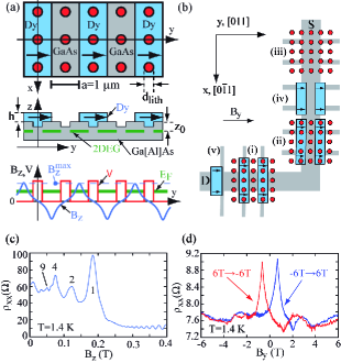
A heterostructure with a 2DEG below the surface is used. After a brief illumination with infrared light, the unpatterned 2DEG has a density of and a mean free path of at liquid helium temperatures. The sample geometry is sketched in Figs. 1(a) and (b). An L-shaped Hall bar, oriented parallel to the natural GaAs cleavage directions, was prepared by optical lithography. Three identical, square antidot lattices (lattice constant ) were patterned on one Hall bar by electron beam lithography and subsequent reactive ion etching. Lithographic antidot diameters of (sample A) as well as (sample B) were prepared on separate Hall bars. As a consequence of a lateral depletion length of around the antidots, this corresponds to electronic diameters of and , respectively, as measured by the Aharonov-Bohm oscillation period observed in large magnetic fields. Iye et al. (2004); sup Since fro sample A and for sample B, respectively, these LSLs reside well inside the classical regime. After the definition of the antidots, Dy stripes of width and a period of were prepared on top of two antidot lattices by electron beam lithography, enabling measurements of all resistivity components in one cooldown, see Fig. 1(b). The Dy stripes have a thickness of to ensure a strong fringe field when magnetized. In sample A, they were deposited directly on the GaAs, while in sample B, a homogeneous film of Cr plus Au thickness was evaporated on top of the antidot lattice prior to the Dy deposition. This allows us to estimate the role of strain effects Ye et al. (1995); Beton et al. (1990) possibly induced by the Dy stripes, which are centered at the columns of antidots and aligned parallel to the x-direction. The lateral size of the superlattices is in longitudinal and in transverse direction ( unit cells). For control measurements, the Hall bar furthermore contains a nominally identical magnetic stripe array without the antidots underneath, and the edge of a Dy film in a Hall cross for Hall magnetometry.Johnson et al. (1997); Cerchez and Heinzel (2011)
The samples were inserted in a gas flow cryostat with a variable temperature insert and a base temperature of . The system is equipped with a magnet of maximum field strength. The external magnetic field was applied in the y - direction. It magnetizes the Dy stripes to a magnetization of . The 2DEG responds predominantly to the z-component of the fringe field of the Dy stripes, and we therefore neglect the influence of in-plane magnetic fields on the 2DEG throughout this paper. The magnetic field profile
is indicated in the lowermost section of Fig. 1(a). From the fringe field of a perfectly magnetized stripe, one expects Vanura et al. (2000)
| (1) |
where is the distance between the 2DEG and the bottom of the Dy film, j is an integer and N denotes the total number of Dy stripes. This magnetic profile has peaks of alternating sign with amplitude . The maximum magnetization of our Dy films is for , corresponding to an upper limit of . The coercive magnetic field is . The resistivity components with were determined by applying an AC current of with a frequency of from source S to drain D, see Fig. 1(b), and by measuring the electrostatic potentials in x- and y-direction at voltage probes with a lock-in amplifier.
III EXPERIMENTAL RESULTS
In Figure 1 (c) and (d), the magnetoresistivities of the LSL components of sample A for the two hybrid LSL components, namely the square antidot lattice (iii) and the array of magnetic stripes (iv), respectively, are reproduced. The antidot lattice reveals the well-known commensurability resonances with resistivity maxima at perpendicular magnetic fields where the cyclotron orbit is commensurate with one, two, four or nine enclosed antidots.Weiss et al. (1991); Ensslin and Petroff (1990); Lorke et al. (1991) For , Shubnikov - de Haas oscillations set in. of the Dy stripes shows a peak centered at and some weak features at larger magnetizations. This type of magnetoresistivity of magnetic stripe arrays in in-plane magnetic fields has been studied theoretically,Ibrahim and Peeters (1995) while to the best of our knowledge, experiments have been reported only in related configurations.Nogaret et al. (2011) Numerical simulations based on the classical Kubo formalism (see below for details) give a weak, positive magnetoresistivity without fine structure,sup as measured for . This indicates that the peak at is not an intrinsic classical property of the magnetic profile itself, and we tentatively attribute it to the frequently observed and still not fully understood negative colossal magnetoresistance in high-mobility 2DEGs,Bockhorn et al. (2011); Hatke et al. (2011); Shi et al. (2014) which is beyond our focus here, possibly in combination with other effects like weak localization. The strength of this feature depends on the cooldown cycle. It should be emphasized that of the 2DEG underneath the Dy array is constant over the full scan range within . For the following, this contribution can therefore be neglected.
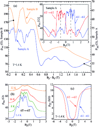
The diagonal magnetoresistivities and of the hybrid LSLs are reproduced in Fig. 2, and we first focus on as observed on samples A and B (a). As is detuned away from , a positive magnetoresistivity is observed. As is further increased, two peaks are seen, separated by a pronounced minimum. Around , a decrease of by roughly a factor of 2 is seen, followed by a broad maximum that extends up to . These most prominent features appear in sample B at somewhat larger magnetic fields than in sample A. Also, even though the positive magnetoresistance is less pronounced in sample A than in sample B, sample A shows clear additional finer structures, some of which are also adumbrated in of sample B. These differences can be traced back to the Cr/Au electrode present in sample B, as will be discussed below in more detail. In the following, we focus on sample A. In the inset of Fig. 2 (a), the hysteretic behavior of is reproduced. The features are fairly symmetric about , while the symmetry of the up-sweep to the down-sweep about is close to perfect. This behavior indicates that the magnetization of the Dy stripes is not perfectly antisymmetric about (see below). These magnetoresistivity features show a weak temperature dependence, see Fig. 2 (b), and the most pronounced ones remain visible up to . This suggests that they should be interpretable within a classical picture. They are furthermore superimposed to a slowly varying negative magnetoresistivity that extends to , after which it increases slightly. This background depends somewhat on the cooldown cycle. The strong positive magnetoresistivity in a narrow interval around is still clearly visible at , and behaves similarly to that one observed in two-dimensional antidot lattices, see also Fig. 1 (c). It is due to a - induced increase in scattering at the antidots and is of no further interest here.
A smooth increase of is observed as is driven away from . A sharp increase sets in for and stops for , see Fig. 2 (c). The shape of strongly resembles that one observed for single magnetic barriers,Vanura et al. (2000) as well as magnetic barriers in series of alternating polarity. Kubrak et al. (1999) Within a classical picture, the increasing amplitude of reflects an increasing fraction of the incident electrons that gets reflected at the magnetic barrier. Above a threshold amplitude of , electrons can only pass the barrier via drift at the edges of the Hall bar, or by scattering events inside the magnetic barrier.Cerchez et al. (2007) These effects cause a saturation of at large . Since our ferromagnetic array represents an array of magnetic double barriers in series, Kubrak et al. (1999), can thus be qualitatively understood in terms of the properties of magnetic double barriers with the antidots acting as scatterers, sup and is not a unique signature of the the hybrid lattice. The onset of the sharp increase of furthermore correlates with the end of the negative magnetoresistivity in x-direction. Comparison of to reveals that the transport at large magnetic fields is highly anisotropic. For example, for , the ratio reaches a value of . This suggests that for sufficiently large magnetization of the Dy stripes, the electrons are guided along the x-direction by the magnetic modulation, while crossing the magnetic walls is highly unlikely.
The off-diagonal components of the magnetoresistivity tensor were measured as well.sup Since the average perpendicular magnetic field is zero, they vanish to a good approximation in the magnetic field range where the resonances in appear and are thus not very helpful for their interpretation.
IV MODEL CALCULATION AND DISCUSSION
A coarse estimation, to be substantiated below, reveals that for , is too weak to generate closed cyclotron-type orbits. Therefore, the magnetoresistivity resonances must originate from open trajectories. This situation is quite different in comparison to antidot lattices in homogeneous magnetic fields where closed orbits, runaway trajectories and chaotic orbits coexist and all contribute to the magnetoresistivity with a magnetic field-dependent weight.Zozoulenko et al. (1997) Open cycloid orbits are absent as well in the interval where the resonances appear, and it is therefore expected that snake trajectories play an important role, the most obvious type of which is centered at the roots of and runs along columns of antidots in x-direction. Since this is a classical picture and moreover the most pronounced features of the magnetoresistivity show a weak temperature dependence, it appears plausible to model them using the classical Kubo formalism. The code we use has been presented in detail elsewhere Meckler et al. (2005) and is therefore only briefly sketched here. We show the simulations for the parameters of sample A. Electrons are injected at random locations inside a unit cell of the LSL. They initially move in random directions with their Fermi velocity of . The incremental change of the direction of motion by the inhomogeneous magnetic field given by Eq. (1) is calculated with a step width of , and specular reflection at the antidots with is assumed. Furthermore, is used, and we assume that the antidot potential is hard-wall, as justified by the large ratio. The simulations are carried out for zero temperature. From the simulated diffusion tensor obtained via the Kubo formula, the magnetoresistivity components are obtained via the Einstein relation for a degenerate 2DEG.
Figure 3 (a) shows the simulated magnetoresistivity as a function of the maximum of the perpendicular magnetic field , see also Figs. 1 (a) and (b).
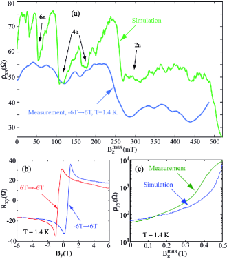
As in the experiment, several features in are observed. Close to , a positive magnetoresistivity is present. For , a series of resistivity minima at and is visible. A clear but weaker additional minimum is visible at . Above a sharp decrease of at , a broad minimum around is present, followed by some weakly pronounced maxima and minima. Finally, another sharp decrease of around is observed. A direct comparison with the measurements requires knowledge of the transformation function . Conceptually, it can be determined by Hall magnetometry of the stripe array on top of Hall crosses well inside the diffusive regime. In the ballistic or quasi-ballistic regime, the Hall voltage translates into the magnetization by nontrivial correction factors, Geim et al. (1997); Cerchez and Heinzel (2011) the detailed discussion of which is beyond our scope here. Since such an estimation would still assume perfect, mono-domain magnetization of the Dy stripes as well as a certain shape of the fringe field, some uncertainty would remain. Therefore, in order to estimate , we restricted ourselves to Hall magnetometry of the edge of a Dy film, prepared in the same process step as the magnetic lattice. The measured Hall voltage as a function of , reproduced in Fig. 3 (b), shows a marked peak where the average cyclotron diameter equals the width of the voltage probe. The decrease of the Hall voltage at larger magnetic fields originates from ballistic effects.Cerchez and Heinzel (2011) The asymmetry of the Hall voltage furthermore indicates that the magnetization of the film is not perfect. Therefore, we compare the measured data to the simulations by scaling it with an approximated function , obtained numerically along the lines of Ref. Cerchez and Heinzel, 2011, where is roughly proportional to for and depends only weakly on for larger applied magnetic fields. This analysis of the Hall magnetometry indicates a saturation magnetization for the Dy stripes of , and can be read out directly. The data measured at sample A in the up-sweep for in Fig. 2 (a) are scaled accordingly and replotted in Fig. 3 (a) as a function of , which allows a more direct comparison to the simulations.
Even though the simulated function deviates from the experimental trace in several aspects, the most prominent features are reproduced qualitatively, namely the positive magnetoresistivity around , minima close to and , the decrease of at , and some weakly pronounced maxima and minima at larger magnetic fields. The sharp decrease of of around is not observed experimentally, most likely because our fringe fields are too weak.
The simulation of is compared to the scaled experimental data in Fig. 3 (c). Very good agreement is found for , while the strong increase of the resistivity around is reproduced as well, though shifted to slightly higher magnetic fields. Further simulations sup show that the presence of the antidots does influence to some extent, but the overall behavior is dominated by the magnetic barriers and is not an effect of the hybrid superlattice.
We proceed by interpreting the magnetoresistivity features in terms of the electron dynamics which determines the components of the magnetoconductivity tensor.sup The off-diagonal elements and are approximately independent of and of the order of . decreases from at to almost zero at . Only shows resonances as is changed. This implies that and , while . The sharp increase of (see Ref. sup, ) and at has thus its origin in the strongly suppressed diagonal conductivity in y-direction.
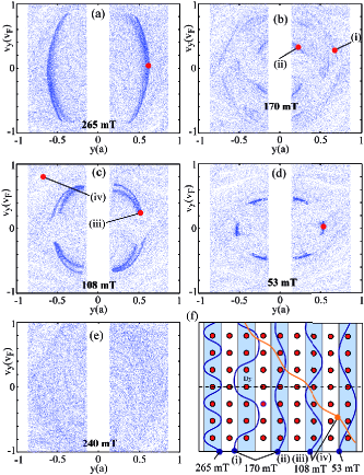
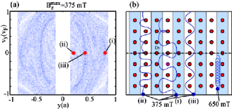
A deeper insight into the underlying electron dynamics can be gained by looking at characteristic electron trajectories. They can be identified with the help of Poincar sections, which illustrate the dynamics of the electrons by their coordinates in a cross section of the phase space ( and denote the position and velocity coordinates, respectively). We start with a discussion of the minima of at smaller magnetic fields, . Each dot in Figs. 4 (a-e) represents the coordinates of an electron passing with through one of the - planes located at at , where is an integer. The Poincar section for (a) shows a pronounced accumulation of the electrons in a semicircle-like structure that extends over 85% of possible components. This region hosts quasi-commensurate snake trajectories with a wavelength very close to 2a. They run parallel to the magnetic stripes, as illustrated by the sample trajectories shown Fig. 4 (f), and typically get scattered at the antidots after less than 30 snake periods. Likewise, the Poincar sections for the minima of at (b), (c), and at (d) reveal that here, quasi-commensurate snake trajectories of various periodicity exist. They extend along the x - direction, and their weight decreases as the magnetic field is decreased, which correlates with the magnitude of the corresponding resistivity dips. Outside the resistivity minima, such an accumulation of electrons in snake trajectories is not seen in the Poincar sections, as illustrated for in Fig. 4 (e).
In addition, snake orbits exist which run at an angle to the x-direction, as exemplified in Fig. 4 (f). In the Poincar sections, such trajectories form white regions, since the electrons do not return to the column in which the electrons start. They can be found over the whole interval where resonances are observed, and we do not find a correlation between their weight in the Poincar section and the magnetoresistivity. We furthermore emphasize that, as anticipated above, closed orbits are absent. It thus emerges that the minima of for correlate with the presence of quasi-commensurate snake trajectories that run parallel to the magnetic stripes for many antidot periods, while snake trajectories running in other directions do not show such a correlation. Both the depletion and accumulation regions of the Poincar sections are embedded in an approximately homogeneously filled background, which is due to electrons that move in snake orbits as well, but experience frequent scattering at the antidots. Typically, such trajectories complete no more that two snake periods before they get scattered. sup We note that both the accumulation and the depletion regions contain mostly not perfectly periodic trajectories and are thus chaotic as well. Regular orbits should exist inside the accumulation regions, but we have been unable to identify such points in the Poincar sections, which indicates that the regular regions have a very small volume. The composition of the phase space of this hybrid LSL is thus different to that one of antidot lattices where disjunct, extended regular and chaotic regions coexist.
It is remarkable that adjacent resistivity minima sometimes correlate with accumulations of snake orbits of the same periodicity. For example, the minima at and at both correlate with the accumulation of snake trajectories with a period close to 4a. While the snake trajectories that belong to the pronounced minimum of at remain commensurate over a relatively large interval of magnetic fields and initial conditions, those found at the weak minimum at , like the two shown in (f) with their location indicated in the Poincar section in (b), are more fragile.
For , the simulation shows a series of weakly pronounced features that end with a strong decrease of at . Qualitatively similar features are observed experimentally for sample A and can be only guessed for sample B. In this interval, the Poincar sections show a rich pattern of accumulation regions, together with a few depleted areas, see Fig. 5 (a). This pattern evolves smoothly as a function of without changing its qualitative appearance. The snake trajectories in this interval have a period close to 2a and show only a few oscillations before they get scattered. We also find occasional trajectory segments of skipping orbits, see Fig. 5 (b). Thus, the magnetoresistivity features in the interval do not correlate in a straightforward way with characteristic trajectories.
The limit of large magnetic fields is characterized by . It is not experimentally accessible in our samples. The simulations suggest that the decrease of originates from the formation of cycloid trajectories which drift along the magnetic field peaks. An example of such a trajectory is shown in Fig. 5 (b). For , cycloid orbits exist that never hit an antidot. Therefore, highly conductive channels in x-direction are formed.
We conclude this section by discussing possible reasons for the differences observed between sample A and sample B, as well as for the deviations between the simulations and the experiments. The most prominent features in sample B appear at higher magnetic fields than their respective counterparts in sample A. With the support of the corresponding numerical simulations, this can be traced back to the larger distance of the Dy stripes to the 2DEG due to the Cr/Au layer in between, which makes a higher magnetization necessary to achieve a fringe field of the same magnitude at the depth of the 2DEG. Also, the less prominent features observed at sample A are suppressed in sample B. This may be due to the larger antidot diameters in sample B which is known to smear out commensurability resonances.Weiss et al. (1991). Also, gating of high mobility heterostructures can decrease the mobility.Roessler et al. (2010)
The simulated amplitudes of the commensurability oscillations are furthermore stronger than the measured ones. We attribute this partly to the deviations of the real magnetic field profile from the simulated one, which is to be expected from the asymmetric magnetization characteristics of the Dy film. Deviations from the assumed hard-wall potential may deform the trajectories, thereby weakening the resonances. Another possible reason are piezoelectric effects due to strain imposed by the Dy stripes, which could modulate the electron density and the mobility for our crystalligraphic orientation of the Hall bars. This effect has been reported in the literature to get attenuated by depositing the stripes on top of a homogeneous metallic layer.Ye et al. (1995) Therefore, by comparing the measurements of sample A with those of sample B, we conclude that if strain effects were relevant, they would generate additional fine structure rather than smearing them out. To further elucidate this issue, we have performed numerical simulations as described above, with an additional electrostatic potential of a cosine shape in y direction with the period of the magnetic stripes and a rather strong amplitude of , in accordance to typical values found in the literature.Beton et al. (1990); Larkin et al. (1997) Somewhat surprisingly, we do not find significant deviations of the resistivity from the unmodulated case (not shown) and therefore conclude that the magnetic field gradient dominates over electrostatic effects in the regime where the resonances are observed. Strain effects thus do not play a prominent role. Also, the simulation neglects finite size effects. For example, a magnetic barrier close to the Hall bar edges induces drift, and electron scattering at the Hall bar edges may provide additional conductance channels. Finally, at the large in-plane magnetic fields present in our implementation, magnetic mass effects can deform the snake trajectories to a small extent.SotomayorChoque et al. (2002)
V SUMMARY AND CONCLUSIONS
Hybrid magneto-electric lateral superlattices composed of a two-dimensional antidot array and a one-dimensional magnetic modulation have been defined in high-mobility two-dimensional electron gases and studied by transport experiments in a configuration with vanishing average perpendicular magnetic field. Despite the absence of closed trajectories, pronounced classical magnetoresistivity resonances have been observed. The magnetoresistivity minima correlate with the accumulation of electrons in snake trajectories, as observed in Poincar sections, that are quasi-commensurate with the antidot lattice and oriented along the direction in which the magnetic field is homogeneous. Snake trajectories running in other directions are present as well, but their appearance does not correlate with the resistivity minima. The Poincar sections do not show extended regular islands. We hope that these rsults will trigger quantum simulations of this system which should be able to interpret the magnetoresistivity resonances on a more fundamental level. The longitudinal magnetoresistivity is furthermore strongly anisotropic, with resistivity ratios above 200 for large magnetic fields. To a good approximation, however, the magnetoresistance in the direction perpendicular to the magnetic stripes can be understood as a resistance of magnetic barriers in series and does not reveal superlattice-specific properties. Further experiments may comprise the application of additional homogeneous perpendicular magnetic fields, a more detailed study of , the interaction of the electrons in snake trajectories with resonant electromagnetic radiation, or magnetic mass effects.
The authors would like to thank HHU Düsseldorf for financial support.
References
- Weiss et al. (1989) D. Weiss, K. von Klitzing, K. Ploog, and G. Weimann, Europhys. Lett. 8, 179 (1989).
- Winkler et al. (1989) R. W. Winkler, J. P. Kotthaus, and K. Ploog, Phys. Rev. Lett. 62, 1177 (1989).
- Weiss et al. (1991) D. Weiss, M. L. Roukes, A. Menschig, P. Grambow, K. von Klitzing, and G. Weimann, Phys. Rev. Lett. 66, 2790 (1991).
- Ensslin and Petroff (1990) K. Ensslin and P. M. Petroff, Phys. Rev. B 41, 12307 (1990).
- Lorke et al. (1991) A. Lorke, J. P. Kotthaus, and K. Ploog, Phys. Rev. B 44, 3447 (1991).
- Carmona et al. (1995) H. A. Carmona, A. K. Geim, A. Nogaret, P. C. Main, T. J. Foster, M. Henini, S. P. Beaumont, and M. G. Blamire, Phys. Rev. Lett. 74, 3009 (1995).
- Ye et al. (1995) P. D. Ye, D. Weiss, R. R. Gerhardts, M. Seeger, K. von Klitzing, K. Eberl, and H. Nickel, Phys. Rev. Lett. 74, 3013 (1995).
- Edmonds et al. (2001) K. W. Edmonds, B. L. Gallagher, P. C. Main, N. Overend, R. Wirtz, A. Nogaret, M. Henini, C. H. Marrows, B. J. Hickey, and S. Thoms, Phys. Rev. B 64, 041303 (2001).
- Beenakker (1989) C. W. J. Beenakker, Phys. Rev. Lett. 62, 2020 (1989).
- Ibrahim et al. (1997) I. S. Ibrahim, V. A. Schweigert, and F. M. Peeters, Phys. Rev. B 56, 7508 (1997).
- Gerhardts (1996) R. R. Gerhardts, Phys. Rev. B 53, 11064 (1996).
- Shi et al. (2002) J. Shi, F. M. Peeters, K. W. Edmonds, and B. L. Gallagher, Phys. Rev. B 66, 035328 (2002).
- Eroms et al. (2002) J. Eroms, M. Tolkiehn, D. Weiss, U. Rssler, J. de Boeck, and G. Borghs, Europhys. Lett. 58, 569 (2002).
- Fleischmann et al. (1992) R. Fleischmann, T. Geisel, and R. Ketzmerick, Phys. Rev. Lett. 68, 1367 (1992).
- Fleischmann et al. (1994) R. Fleischmann, T. Geisel, and R. Ketzmerick, Europhys. Lett. 25, 219 (1994).
- Schuster et al. (1993) R. Schuster, K. Ensslin, J. P. Kotthaus, M. Holland, and C. Stanley, Phys. Rev. B 47, 6843 (1993).
- Weiss et al. (1994) D. Weiss, K. Richter, E. Vasiadou, and G. Ltjering, Surf. Sci. 305, 408 (1994).
- Nihey et al. (1995) F. Nihey, S. W. Hwang, and K. Nakamura, Phys. Rev. B 51, 4649 (1995).
- Hofstadter (1976) D. Hofstadter, Phys. Rev. B 14, 2239 (1976).
- Pfannkuche and Gerhardts (1992) D. Pfannkuche and R. R. Gerhardts, Phys. Rev. B 46, 12606 (1992).
- Geisler et al. (2004) M. C. Geisler, J. H. Smet, V. Umansky, K. von Klitzing, B. Naundorf, R. Ketzmerick, and H. Schweizer, Phys. Rev. Lett. 92, 256801 (2004).
- Weiss et al. (1993) D. Weiss, K. Richter, A. Menschig, R. Bergmann, H. Schweizer, K. von Klitzing, and G. Weimann, Phys. Rev. Lett. 70, 4118 (1993).
- Aharonov and Bohm (1959) Y. Aharonov and D. Bohm, Phys. Rev. 115, 485 (1959).
- Altshuler et al. (1981) B. L. Altshuler, A. G. Aronov, and B. Z. Spivak, JETP Lett. 33, 94 (1981).
- Richter (1995) K. Richter, Europhys. Lett. 29, 7 (1995).
- Umansky et al. (1997) V. Umansky, R. de Picciotto, and M. Heiblum, Appl. Phys. Lett. 71, 683 (1997).
- Roessler et al. (2010) C. Roessler, T. Feil, P. Mensch, T. Ihn, K. Ensslin, D. Schuh, and W. Wegscheider, New J. Phys. 12, 043007 (2010).
- Nogaret (2010) A. Nogaret, J. Phys. Cond. Mat. 22, 253201 (2010).
- Iye et al. (2004) Y. Iye, M. Ueki, A. Endo, and S. Katsumoto, J. Phys. Soc. Japan 73, 3370 (2004).
- (30) See Supplemental Material at [URL will be inserted by publisher] for details.
- Beton et al. (1990) P. H. Beton, E. S. Alves, P. C. Main, L. Eaves, M. W. Dellow, M. Henini, O. H. Hughes, S. P. Beaumont, and C. D. W. Wilkinson, Phys. Rev. B 42, 9229 (1990).
- Johnson et al. (1997) M. Johnson, B. R. Bennett, M. J. Yang, M. M. Miller, and B. V. Shanabrook, Appl. Phys. Lett. 71, 974 (1997).
- Cerchez and Heinzel (2011) M. Cerchez and T. Heinzel, Appl. Phys. Lett. 98, 232111 (2011).
- Vanura et al. (2000) T. Vanura, T. Ihn, S. Broderick, K. Ensslin, W. Wegscheider, and M. Bichler, Phys. Rev. B 62, 5074 (2000).
- Ibrahim and Peeters (1995) I. S. Ibrahim and F. M. Peeters, Phys. Rev. B 52, 17321 (1995).
- Nogaret et al. (2011) A. Nogaret, F. Nasirpouri, J.-C. Portal, H. E. Beere, D. A. Ritchie, A. T. Hindmarch, and C. H. Marrows, Europhys. Lett. 94, 28001 (2011).
- Bockhorn et al. (2011) L. Bockhorn, P. Barthold, D. Schuh, W. Wegscheider, and R. J. Haug, Phys. Rev. B 83, 113301 (2011).
- Hatke et al. (2011) A. T. Hatke, M. A. Zudov, L. N. Pfeiffer, and K. W. West, Phys. Rev. B 83, 121301 (2011).
- Shi et al. (2014) Q. Shi, P. D. Martin, Q. A. Ebner, M. A. Zudov, L. N. Pfeiffer, and K. W. West, Phys. Rev. B 89, 201301(R) (2014).
- Kubrak et al. (1999) V. Kubrak, F. Rahman, B. L. Gallagher, P. C. Main, M. Henini, C. H. Marrows, and M. A. Howson, Appl. Phys. Lett. 74, 2507 (1999).
- Cerchez et al. (2007) M. Cerchez, S. Hugger, T. Heinzel, and N. Schulz, Phys. Rev. B 75, 035341 (2007).
- Zozoulenko et al. (1997) I. V. Zozoulenko, F. A. Maao, and E. H. Hauge, Phys. Rev. B 56, 4710 (1997).
- Meckler et al. (2005) S. Meckler, T. Heinzel, A. Cavanna, G. Faini, U. Gennser, and D. Mailly, Phys. Rev. B 72, 035319 (2005).
- Geim et al. (1997) A. K. Geim, S. V. Dubonos, J. G. S. Lok, I. V. Grigorieva, J. C. Maan, L. T. Hansen, and P. E. Lindelof, Appl. Phys. Lett. 71, 2379 (1997).
- Larkin et al. (1997) I. A. Larkin, J. H. Davies, A. R. Long, and C. Ramon, Phys. Rev. B 56, 15242 (1997).
- SotomayorChoque et al. (2002) N. M. SotomayorChoque, G. M. Gusev, J. R. Leite, A. A. Bykov, L. V. Litvin, N. T. Moshegov, A. I. Toropov, D. K. Maude, and J. C. Portal, Phys. Rev. B 66, 035324 (2002).