Unidirectional spin Hall magnetoresistance in ferromagnet/normal metal bilayers
Abstract
Magnetoresistive effects are usually invariant upon inversion of the magnetization direction. In noncentrosymmetric conductors, however, nonlinear resistive terms can give rise to a current dependence that is quadratic in the applied voltage and linear in the magnetization. Here we demonstrate that such conditions are realized in simple bilayer metal films where the spin-orbit interaction and spin-dependent scattering couple the current-induced spin accumulation to the electrical conductivity. We show that the longitudinal resistance of TaCo and PtCo bilayers changes when reversing the polarity of the current or the sign of the magnetization. This unidirectional magnetoresistance scales linearly with current density and has opposite sign in Ta and Pt, which we associate to the modification of the interface scattering potential induced by the spin Hall effect in these materials. Our results suggest a new route to detect magnetization switching in spintronic devices using a two-terminal geometry, which applies also to heterostructures including topological insulators.
The effects of the magnetization on the electric conductivity of metals have been studied for a long time Thomson (1856), providing understanding of fundamental phenomena associated to electron transport and magnetism as well as manyfold applications in sensor technology. The anisotropic magnetoresistance (AMR), the change of the resistance of a material upon rotation of the magnetization, is a prominent manifestation of spin-orbit coupling and spin-dependent conductivity in bulk ferromagnets Campbell et al. (1970); McGuire and Potter (1975). In thin film heterostructures, the additional possibility of orienting the magnetization of stacked ferromagnetic layers parallel or antiparallel to each other gives rise to the celebrated giant magnetoresistance (GMR) effect Baibich et al. (1988); Binasch et al. (1989), which has played a major role in all modern developments of spintronics. Together with the early spin injection experiments Johnson and Silsbee (1985); Jedema et al. (2001), the study of GMR revealed how nonequilibrium spin accumulation at the interface between ferromagnetic (FM) and normal metal (NM) conductors governs the propagation of spin currents Johnson and Silsbee (1987); Van Son et al. (1987); Valet and Fert (1993); Maekawa et al. (2012) and, ultimately, the conductivity of multilayer systems Valet and Fert (1993); Brataas et al. (2006).
Recently, it has been shown that significant spin accumulation at a FMNM interface can be achieved using a current-in-plane (CIP) geometry owing to the spin Hall effect (SHE) in the NM Sinova et al. . When FM is a metal and NM is a heavy element such as Pt or Ta, the spin accumulation is strong enough to induce magnetization reversal of nm-thick FM layers at current densities of the order of A/cm2 (Refs. Miron et al., 2011; Liu et al., 2012; Garello et al., 2013). When FM is an insulator, such as yttrium iron garnet, the SHE causes an unusual magnetoresistance associated to the back-flow of a spin current into the NM when the spin accumulation is aligned with the magnetization of the FM, which increases the conductivity of the NM due to the inverse SHE Nakayama et al. (2013); Hahn et al. (2013); Althammer et al. (2013); Miao et al. (2014). This so-called spin Hall magnetoresistance (SMR) is characterized by , where is the resistance measured when the magnetization () is saturated parallel to , and differs from the conventional AMR in polycrystalline samples, for which and (Ref. McGuire and Potter, 1975).
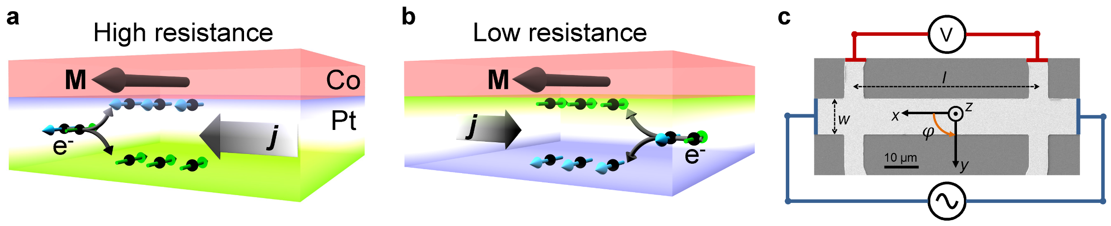
In this work, we report on a new magnetoresistance effect occurring in FMNM bilayers with the NM possessing large SHE. The effect combines features that are typical of the current-in-plane (CIP) GMR and SHE, whereby the spin accumulation induced by the SHE in the NM replaces one of the FM polarizers of a typical GMR device. Differently from GMR, however, this effect introduces a nonlinear dependence of the resistance on the current, which gives it unique unidirectional properties: the resistivity changes when reversing either the sign of the magnetization or the polarity of the current, increasing (decreasing) when the SHE-induced non equilibrium magnetization at the FMNM interface is oriented parallel (antiparallel) to the magnetization of the FM, as illustrated in Fig. 1a,b. We associate this phenomenon to the modulation of the FMNM interface resistance due to the SHE-induced spin accumulation, which gives rise to a nonlinear contribution to the longitudinal conductivity that scales proportionally with the current density and has opposite sign in Pt and Ta. Contrary to the linear magnetoresistive effects, including the AMR, GMR, and SMR described above, which are even with respect to the inversion of either the current or magnetization owing to the time reversal symmetry embodied in the Onsager’s reciprocity relations, here we observe , providing a unidirectional contribution to the magnetoresistance in simple bilayer systems.
Sample layout
The samples studied in this work are Pt(1-9nm)Co(2.5nm) and Ta(1-9nm)Co(2.5nm) films with spontaneous in-plane magnetization, capped by 2 nm AlOx and patterned in the shape of Hall bars of nominal length m, width m, and , as shown in Fig. 1c.
Additional control experiments were carried out on single Co, Ta, and Pt films, and Ta(1,6nm)Cu(2,4,6nm)Co(2.5nm) trilayers. To characterize the magnetic and electrical properties of these layers we performed harmonic measurements of the longitudinal resistance (, see Supplementary Information) and transverse Hall resistance () Garello et al. (2013); Avci et al. (2014a); Hayashi et al. (2014); Avci et al. (2014b) as a function of a vector magnetic field defined by the polar and azimuthal coordinates and . The measurements were carried out at room temperature by injecting an ac current of frequency Hz and simultaneously recording the first () and second harmonic resistance () between the contacts shown in Fig. 1c while rotating the sample in a uniform magnetic field of 1.7 T. Here, represents the linear response of the samples to the current, that is, the conventional resistance. In order to include the different magnetoresistive angular dependencies in a single expression we write this term as
| (1) |
where and are the polar and azimuthal angles of , as schematized in Fig. 2a. describes resistance contributions that vary quadratically with the applied voltage and includes the current-induced changes of resistivity that are the main focus of this work.
Magnetoresistance measurements
Figure 2b and c show the resistance of Ta(6nm)Co(2.5nm) and Pt(6nm)Co(2.5nm) layers during rotation of the applied field in the , , and planes. We observe a sizeable magnetoresistance (MR) in all three orthogonal planes and for both samples, in agreement with previous measurements on PtCo filmsKobs et al. (2011); Lu et al. (2013). The resistivity of Ta(6nm)Co(2.5nm) [Pt(6nm)Co(2.5nm)] is 108.9 (36.8) cm and the MR ratios are [] and [], showing a large SMR-like behavior compared to TaYIG and PtYIGNakayama et al. (2013); Hahn et al. (2013).
The solid lines represent fits to the MR using Eq. 1 and simultaneously measured via the anomalous Hall resistance (see Supplementary Information).
In addition to the linear resistance, we measure an unexpected nonlinear resistance, , which has a different angular dependence compared to and opposite sign in Pt and Ta, as shown in Fig. 2d and e. By fitting the curves with respect to the angles and (solid lines), we find that . In the following, we discuss the type of nonlinear effects that can give rise to such a symmetry.
Spin-orbit torques and thermoelectric contributions
First, we consider oscillations of the magnetization due to the current-induced spin-orbit torques (SOT) Garello et al. (2013); Avci et al. (2014a); Hayashi et al. (2014); Kim et al. (2013); Avci et al. (2014b). As the SOT are proportional to the current, ac oscillations of the magnetization can introduce second-order contributions to due to the first order MR described by Eq. 1. However, as shown in detail in the Supplementary Information, the SOT-induced signal is not compatible with the angular dependence of . Both the field-like and antidamping-like SOT (as well as the torque due to the Oersted field) vanish for , where is maximum. Moreover, the field-like SOT is small in 2.5 nm thick Co layers Avci et al. (2014b), whereas the antidamping SOT can only induce variations of in the plane with maxima and minima close to and , which we observe to be small and more pronounced in PtCo relative to TaCo (Fig. 2d and e bottom panels).
Second, we analyze the influence of thermal gradients () and related thermoelectric effects. The anomalous Nernst (ANE) and spin Seebeck effect (SSE) Weiler et al. (2012); Kikkawa et al. (2013), both inducing a longitudinal voltage proportional to , can give rise to a similar angular dependence as observed for when (see Supplementary Information). Here, we find that thermoelectric voltages are negligible in PtCo, in agreement with the very small thermal gradients reported for this systemAvci et al. (2014b). In TaCo, on the other hand, the much larger resistivity of Ta relative to Co results in a higher current flowing in the Co layer and a positive . In such a case, the second harmonic signal of thermal origin, , can be simply estimated from its transverse (Hall) counterpart scaled by the geometric factor when the magnetization is tilted in the direction, and subtracted from the raw signal. Accordingly, we find that m in Ta(6nm)Co(2.5nm), which accounts for only about of the total reported in Fig. 2. The same procedure applied to PtCo gives m of the order of 5% of the total , whereas in the control samples lacking a heavy metal we find uniquely a signal of thermal (ANE) origin. We conclude that there is an additional magnetoresistive effect in the PtCo and TaCo bilayers that cannot be accounted for by either current-induced magnetization dynamics or thermoelectric voltages.
Unidirectional spin Hall magnetoresistance
The symmetry as well as the opposite sign of the nonlinear resistance in TaCo and PtCo suggest that it is related to the scalar product of the magnetization with the SHE-induced spin accumulation at the FMNM interface, , giving rise to a chiral MR contribution . This relation describes the general features expected from a unidirectional magnetoresistance driven by the spin Hall effect (USMR). We note that this MR contribution depends on the current direction and that the resistance of the bilayer increases when the direction of the majority spins in the FM and the spin accumulation vector are parallel to each other, and decreases when they are antiparallel. This may appear counterintuitive at first sight, considering that the conductivity of Co is larger for the majority spins. However, as we will discuss later, this behavior is consistent with the theory of GMR in FMNMFM heterostructures Valet and Fert (1993); Camley and Barnaś (1989); Hood and Falicov (1992) when only a single FMNM interface is retained and the SHE is taken into account.
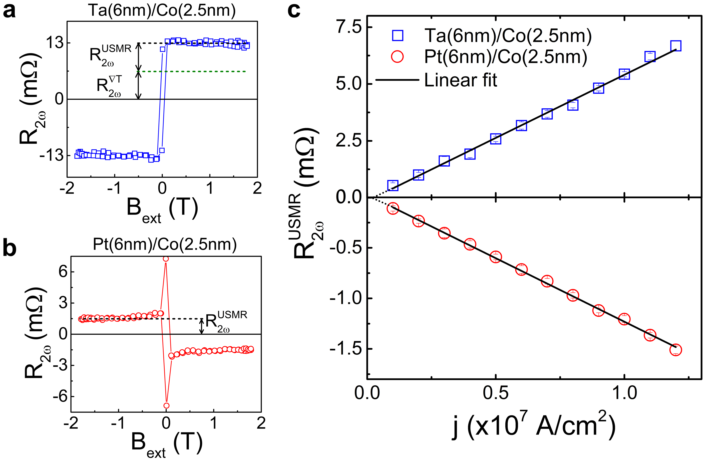
To investigate further the USMR we have measured as a function of an external magnetic field applied parallel to and current amplitude. Figure 3a shows that is constant as a a function of field for TaCo as well as for PtCo (Fig. 3b) and reverses sign upons switching of the magnetization from the to the direction. In the PtCo case we observe also two spikes, which we attribute to the magnetization breaking into domains at low field and giving rise to dynamic effects on the domain walls Garello et al. (2013). Note that the magnetization of PtCo is not fully saturated below 0.65 T due to the large perpendicular magnetic anisotropy of this system, differently from TaCo (Supplementary Information). Figure 3c shows the current dependence of ( for PtCo) obtained by taking the average of the data measured at fields larger than T. is linear with the injected current density and converges to zero within the error bar of the linear fit (black lines).
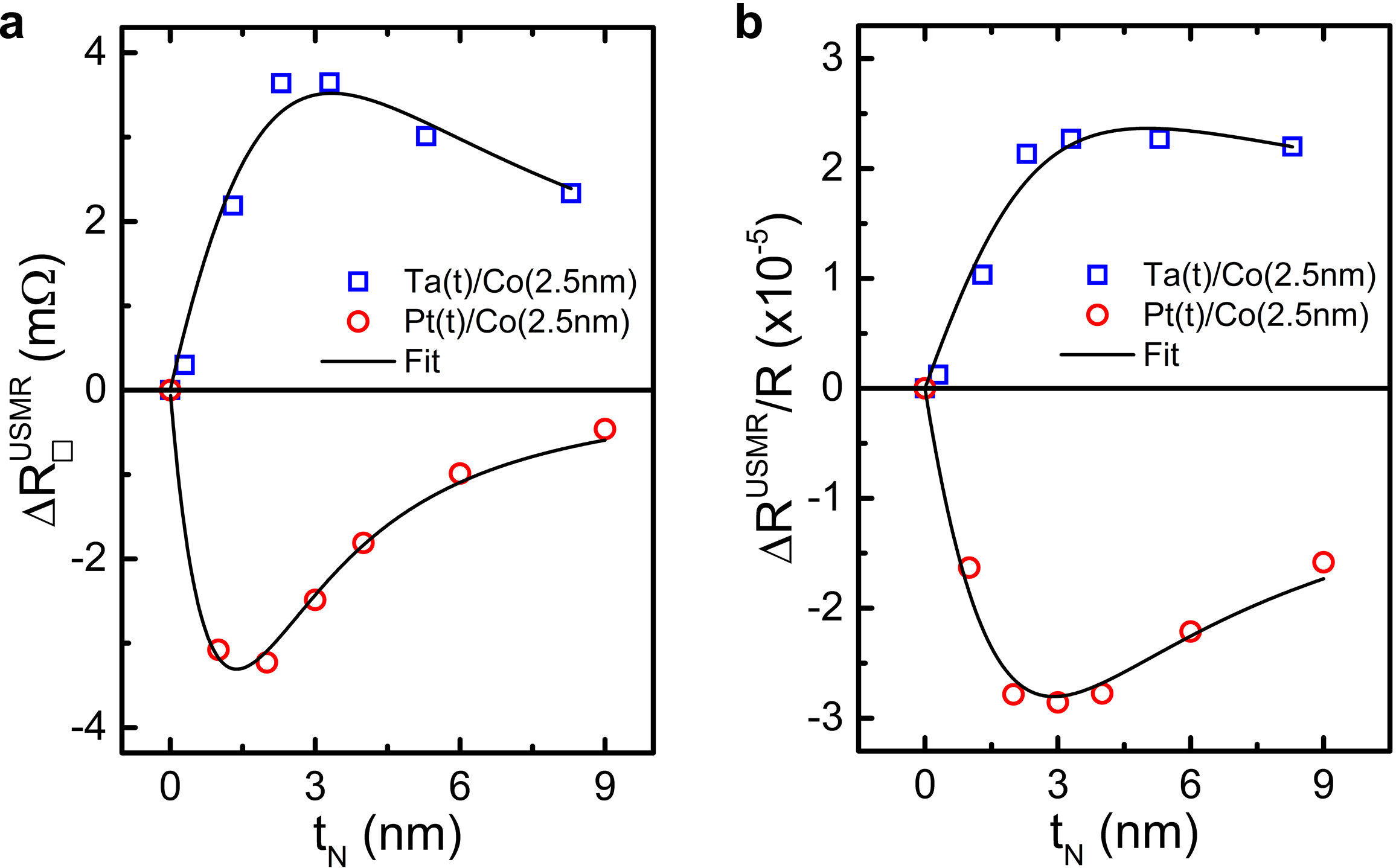
To verify the role of the interfacial spin accumulation due to the SHE we examined the dependence of the USMR on the thickness of the NM. Figure 4a and b show the absolute change of sheet resistance and the relative change of resistivity measured at constant current density as a function of the Ta and Pt thickness. Both curves exhibit qualitatively similar behavior: an initial sharp increase below 2-3 nm and a gradual decrease as the NM layer becomes thicker. We note that the USMR signal is almost absent in Ta(1nm)Co, contrary to Pt(1nm)Co, which we attribute to the oxidation of Ta when deposited on SiO2 and its consequent poor contribution to electrical conduction. The initial increase of the USMR is consistent with the increment of the spin accumulation at the FMNM interface as the thickness of the NM becomes larger than the spin diffusion length, which is of the order of 1.5 nm in both Ta and Pt Hahn et al. (2013); Zhang et al. (2013). Moreover, we observe that the decline of the signal in the thicker samples is stronger in PtCo than in TaCo. This behavior is consistent with Pt gradually dominating the conduction due to its low resistivity, and a smaller proportion of the current experiencing interface scattering in PtCo. Conversely, the high resistivity of Ta shunts the current towards the Co side, increasing the relative proportion of the current affected by scattering at the TaCo interface.
As an additional check to validate these arguments we have performed measurements on single Ta(6nm), Pt(6nm), and Co(8nm) layers as well as on Ta(1,6nm)Cu(2,4,6nm)Co(2.5nm) trilayers, all capped by 2 nm AlOx. The USMR is absent in the Ta, Pt, and Co single layers, which also excludes any self induced magnetoresistive effect Dyakonov (2007) and proves the essential role of the FMNM interface. On the other hand, we find a sizable USMR when a Cu spacer is inserted between Ta and Co, which excludes proximity-induced magnetization as a possible cause for the USMR (see Supplementary Information).
Discussion
Based on the analysis presented above, we conclude that the current-induced spin accumulation creates an additional spin-dependent interface resistance that adds or subtracts to the total resistance depending on sign of the cross product . Given the in-plane geometry, the interpretation of this effect requires a Boltzmann equation approach to model the spin- and momentum-dependent reflection and transmission of electrons at the FMNM interface, equivalent to extending the theory of CIP-GMR Camley and Barnaś (1989); Hood and Falicov (1992) beyond first order and including the SHE. However, a qualitative understanding of the USMR can be derived also by introducing a two current series resistor model and an interface resistance term proportional to the SHE-induced shift of the electrochemical potential between the FM and NM layers. The latter can be calculated using a one-dimensional drift-diffusion approachVan Son et al. (1987); Valet and Fert (1993); Nakayama et al. (2013). We consider two separate conduction channels for the minority (spin ) and majority (spin ) electrons. As in bulk FM, scattering at the interface is spin-dependent due to the unequal density of majority and minority states near the Fermi level, which, in most cases, leads to a larger resistance for minority electrons relative to majority electrons: . This resistance difference is at the heart of the GMR effect, both in the CIPCamley and Barnaś (1989); Hood and Falicov (1992); Dieny (1992) and the current-perpendicular-to-plane (CPP) geometry Valet and Fert (1993); Nguyen et al. (2014). Additionally, when an electric current flows from a FM to a NM or viceversa, another resistance term appears due to the conductivity mismatch between majority and minority electrons on opposite sides of the junction, which results in spin accumulation (Refs. Johnson and Silsbee, 1987; Van Son et al., 1987). This so-called ”spin-coupled interface resistance”, plays a role in CPP-GMR as well as in local and nonlocal spin injection devicesValet and Fert (1993); Jedema et al. (2001); Valenzuela and Tinkham (2006), whereas in the CIP geometry it is normally neglected because there is no net charge flow across the interface and the spin accumulation is assumed to be zero. If we take the SHE into account, however, the transverse spin current flowing between the NM and the FM induces a splitting of the spin-dependent electrochemical potentials and and a net interfacial spin accumulation , which is given by
| (2) |
where is the bare spin accumulation due to the SHE that would occur in a single, infinitely thick NM layer, the spin Hall angle of the NM, and are the resistivity and spin diffusion length of the NM and FM, respectively, and is the interface resistanceValet and Fert (1993). Moreover, the same effect induces a shift of the electrochemical potential of the NM relative to the FM:
| (3) |
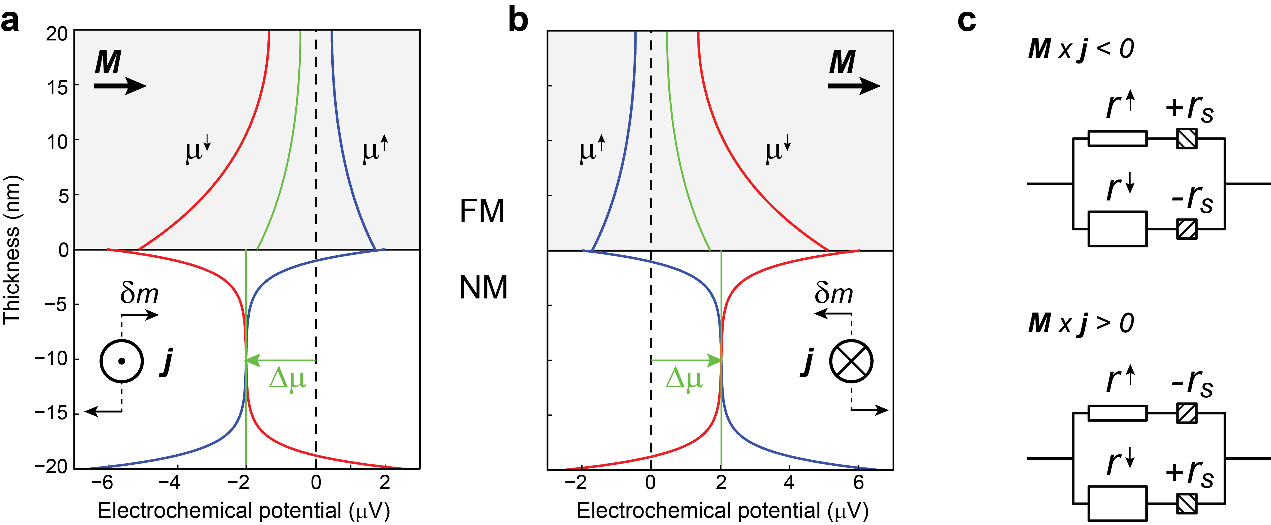
where and . Figure 5a and b show a graphical representation of and ; details about the derivation of Eqs. 2 and 3 are given in the Supplementary Information. A key point is that depends on the product , as the USMR, and is linked with the spin-dependent scattering potential that gives rise to different transmission coefficients for majority and minority electrons at the FMNM interface Zhang et al. (1992). We can thus draw the following qualitative interpretation of the USMR: when the nonequilibrium magnetization induced by the SHE and the magnetization of the FM are parallel to each other (), the transmission of () electrons across the interface is reduced (enhanced) by the accumulation of majority electrons at the FMNM boundary, due to the conductivity mismatch of and spins in the two materials. Likewise, when , the transmission of () electrons across the interface is reduced (enhanced) since minority electrons accumulate at the FMNM boundary. The overall effect is a modulation of the interface resistance of the and spin channels by a nonlinear term , as schematized in Fig. 5c. This two current ( and ) series resistor model shows that such a modulation leads to a resistance difference between the two configurations .
Accordingly, using realistic values of , , and for TaCo and PtCo, we fit the dependence of the USMR on current and NM thickness to the following phenomenological expression (see Supplementary Information): , where is a parameter proportional to representing the amplitude of the effect, is the effective resistance of the FM and interface regions, and is the resistance of the NM. The denominator accounts for the decreased fraction of electrons that scatter at the interface as the thickness of the NM increases. Similarly, we obtain . As shown in Fig. 4, these simple expressions fit and remarkably well, providing also values of nm and nm that are in agreement with previous measurements Hahn et al. (2013); Zhang et al. (2013). Our model thus captures the essential features of the USMR, namely its sign, angular dependence, and proportionality to the current. Detailed calculations including realistic scattering parameters within a nonlinearized Boltzmann approach including the SHE Haney et al. (2013) should be able to account for quantitative aspects of the USMR in different materials. We stress also that the USMR is not uniquely linked to the SHE but may arise also due to other sources of nonequilibrium spin accumulation, such as the Rashba effect at FMNM interfaces and topological insulatorsHaney et al. (2013); Manchon and Zhang (2008); Miron et al. (2010); Mahfouzi et al. (2012) as well as the anomalous Hall effect in FM.
Conclusions
The existence of a nonlinear magnetoresistive term proportional to has both fundamental and practical implications. Identifying which symmetries survive the breakdown of the Onsager relationships in the nonlinear regime is central to the understanding of electron transport phenomena, particularly in mesoscopic and magnetic conductors where such effects can also have thermoelectric and magneto-optical counterparts Sánchez and Büttiker (2004); Rikken et al. (2001). In this respect, the USMR shows that the longitudinal conductivity has an antisymmetric Hall-like component that has so far remained unnoticed. We expect such a component to be a general feature of noncentrosymmetric magnetic systems with strong spin-orbit coupling. We note also that the USMR
differs from the nonlinear MR observed in chiral conductors, such as metal helices Rikken et al. (2001) and molecular crystals Pop et al. (2014), which is proportional to .
In the field of spintronics, nonlinear interactions between spin and charge are emerging as a tool to detect spin currentsVera-Marun et al. (2012) and thermoelectricSlachter et al. (2010) effects, as well as magnetization reversal in dual spin valves Aziz et al. (2009). Although the USMR is only a small fraction of the total resistance, its relative amplitude is of the same order of magnitude of the spin transresistance measured in nonlocal metal spin valvesJedema et al. (2001); Valenzuela and Tinkham (2006), which is a method of choice for the investigation of spin currents. The thermoelectric counterpart of the USMR, related to the spin Nernst effect, may be used to detect heat-induced spin accumulation by modulation of the magnetization rather than an electric current. We note that the electric field created by the USMR is of the order of 2 V/m per 107 A/cm2, which is comparable to the ANEAvci et al. (2014b) and three orders of magnitude larger than the typical electric fields due to the SSEWeiler et al. (2012); Kikkawa et al. (2013).
In terms of applications, the USMR may be used to add 360∘ directional sensitivity to AMR sensors, which are widely employed for position, magnetic field, and current sensing, and already include built-in modulation circuitry for accurate resistance measurements. Most interestingly, the USMR shows that it is possible to realize two-terminal spintronic devices where switching is performed by SOTMiron et al. (2011); Liu et al. (2012) and reading by a resistance measurement. Such a scheme involves only one FM layer and minimum patterning effort. Finally, we believe that there is substantial room for improving the amplitude of the USMR to levels closer to the AMR, either by material or heterostructure engineering. In particular, the USMR could increase significantly in magnetic topological insulator structures due to the very large spin accumulation and reduced bulk conductance reported for these systemsMellnik et al. (2014); Fan et al. (2014).
Methods
Sample preparation. The Pt(1-9nm)Co(2.5nm)AlOx(2nm) and Ta(1-9nm)Co(2.5nm)AlOx(2nm) layers were grown by dc magnetron sputtering on thermally oxidized Si wafers. The deposition rates were 0.185 nm/s for Pt, 0.067 nm/s for Ta, 0.052 nm/s for Co, and 0.077 nm/s for Al. The deposition pressure was 2 mTorr and the power was 50 W for all targets. The Al capping layers were oxidized in-situ by a 7 mTorr O2 plasma at 10 W during 35 s. The layers were subsequently patterned into 6-terminals Hall bars by using standard optical lithography and Ar milling procedures. The Hall bar dimensions are for the current line width, for the Hall branch width, and is the distance between two Hall branches, where varies between 4 and 10 m.
Characterization. All layers possess spontaneous isotropic in-plane magnetization. To determine the saturation magnetization of Co we have performed anomalous Hall effect measurements on an 8 nm-thick Co reference sample with . The field required to fully saturate out-of-plane is about 1.5 T, which, assuming that perpendicular magnetic anisotropy is negligible in this layer, is close to expected of Co. Similar measurements on Ta(6nm)Co(2.5nm) and Pt(6nm)Co(2.5nm) layers give saturation fields of 1.45 T and 0.8 T, respectively. This is attributed to the small (large) perpendicular interface anisotropy contribution of the TaCo (PtCo) interface, reducing the field required to saturate the magnetization out-of-plane. 4-point resistivity measurements on single Co(8nm), Ta(6nm) and Pt(6nm) layers yield cm, cm and cm, in line with expectations for Pt and Co thin films, and the -phase of Ta. The magnetoresistance and Hall voltage measurements were performed at room temperature by using an ac current where Hz, generated by a Keithley-6221 constant current source. For the data reported in Fig. 2 the peak amplitude of the injected ac current was set to 8.5 mA, corresponding to a nominal current density of A/cm2. In other measurements with different device size and thickness, the current was adapted to have the same current density. The longitudinal and transverse voltages were recorded simultaneously by using a 24-bit resolution National Instruments PXI-4462 dynamic signal analyser, during 10 s at each angle position in a uniform external field of 1.7 T. The rotation of the sample was provided by a motorized stage having a precision of 0.02 degrees. The acquired voltages were fast Fourier transformed (FFT) to extract the first and second harmonic voltage signals and . The corresponding resistances are given by and (peak values).
Acknowledgments
This work was funded by the Swiss National Science Foundation (Grant No. 200021-153404) and the European Commission under the Framework Program (SPOT project, Grant No. 318144).
Author contributions
C.O.A., K.G., and P.G. planned the experiments; M.G., A.G., S.F.A., and C.O.A. carried out the sample growth and patterning; C.O.A., K.G., and A.G. performed the measurements; C.O.A. and P.G. analyzed the data and wrote the manuscript. All authors contributed to the discussion of the data in the manuscript and Supplementary Information.
Additional information
Correspondence and requests for materials should be addressed to
C.O.A. (can.onur.avci@mat.ethz.ch) and P.G. (pietro.gambardella@mat.ethz.ch).
References
- Thomson (1856) W. Thomson, Proc. R. Soc. London 8, 546 (1856).
- Campbell et al. (1970) I. Campbell, A. Fert, and O. Jaoul, J. Phys. C 3, S95 (1970).
- McGuire and Potter (1975) T. McGuire and R. Potter, IEEE Trans. Magn. 11, 1018 (1975).
- Baibich et al. (1988) M. N. Baibich, J. M. Broto, A. Fert, F. N. Van Dau, F. Petroff, P. Etienne, G. Creuzet, A. Friederich, and J. Chazelas, Phys. Rev. Lett. 61, 2472 (1988).
- Binasch et al. (1989) G. Binasch, P. Grünberg, F. Saurenbach, and W. Zinn, Phys. Rev. B 39, 4828 (1989).
- Johnson and Silsbee (1985) M. Johnson and R. H. Silsbee, Phys. Rev. Lett. 55, 1790 (1985).
- Jedema et al. (2001) F. Jedema, A. Filip, and B. Van Wees, Nature 410, 345 (2001).
- Johnson and Silsbee (1987) M. Johnson and R. Silsbee, Phys. Rev. B 35, 4959 (1987).
- Van Son et al. (1987) P. Van Son, H. Van Kempen, and P. Wyder, Phys. Rev. Lett. 58, 2271 (1987).
- Valet and Fert (1993) T. Valet and A. Fert, Phys. Rev. B 48, 7099 (1993).
- Maekawa et al. (2012) S. Maekawa, S. O. Valenzuela, E. Saitoh, and T. Kimura, Spin Current (Oxford University Press, 2012).
- Brataas et al. (2006) A. Brataas, G. E. Bauer, and P. J. Kelly, Phys. Rep. 427, 157 (2006).
- (13) J. Sinova, S. O. Valenzuela, J. Wunderlich, C. H. Back, and T. Jungwirth, http://arxiv.org/abs/1411.3249 .
- Miron et al. (2011) I. M. Miron, K. Garello, G. Gaudin, P.-J. Zermatten, M. V. Costache, S. Auffret, S. Bandiera, B. Rodmacq, A. Schuhl, and P. Gambardella, Nature 476, 189 (2011).
- Liu et al. (2012) L. Liu, C.-F. Pai, Y. Li, H. Tseng, D. Ralph, and R. Buhrman, Science 336, 555 (2012).
- Garello et al. (2013) K. Garello, I. M. Miron, C. O. Avci, F. Freimuth, Y. Mokrousov, S. Blügel, S. Auffret, O. Boulle, G. Gaudin, and P. Gambardella, Nature Nanotech. 8, 587 (2013).
- Nakayama et al. (2013) H. Nakayama, M. Althammer, Y.-T. Chen, K. Uchida, Y. Kajiwara, D. Kikuchi, T. Ohtani, S. Geprägs, M. Opel, S. Takahashi, et al., Phys. Rev. Lett. 110, 206601 (2013).
- Althammer et al. (2013) M. Althammer, S. Meyer, H. Nakayama, M. Schreier, S. Altmannshofer, M. Weiler, H. Huebl, S. Geprägs, M. Opel, R. Gross, et al., Phys. Rev. B 87, 224401 (2013).
- Miao et al. (2014) B. Miao, S. Huang, D. Qu, and C. Chien, Phys. Rev. Lett. 112, 236601 (2014).
- Avci et al. (2014a) C. O. Avci, K. Garello, C. Nistor, S. Godey, B. Ballesteros, A. Mugarza, A. Barla, M. Valvidares, E. Pellegrin, A. Ghosh, I. M. Miron, O. Boulle, S. Auffret, G. Gaudin, and P. Gambardella, Phys. Rev. B 89, 214419 (2014a).
- Hayashi et al. (2014) M. Hayashi, J. Kim, M. Yamanouchi, and H. Ohno, Phys. Rev. B 89, 144425 (2014).
- Avci et al. (2014b) C. O. Avci, K. Garello, M. Gabureac, A. Ghosh, A. Fuhrer, S. F. Alvarado, and P. Gambardella, Phys. Rev. B 90, 224427 (2014b).
- Kobs et al. (2011) A. Kobs, S. Heße, W. Kreuzpaintner, G. Winkler, D. Lott, P. Weinberger, A. Schreyer, and H. Oepen, Phys. Rev. Lett. 106, 217207 (2011).
- Lu et al. (2013) Y. Lu, J. Cai, S. Huang, D. Qu, B. Miao, and C. Chien, Phys. Rev. B 87, 220409 (2013).
- Hahn et al. (2013) C. Hahn, G. De Loubens, O. Klein, M. Viret, V. V. Naletov, and J. B. Youssef, Phys. Rev. B 87, 174417 (2013).
- Kim et al. (2013) J. Kim, J. Sinha, M. Hayashi, M. Yamanouchi, S. Fukami, T. Suzuki, S. Mitani, and H. Ohno, Nature Mater. 12, 240 (2013).
- Weiler et al. (2012) M. Weiler, M. Althammer, F. D. Czeschka, H. Huebl, M. S. Wagner, M. Opel, I.-M. Imort, G. Reiss, A. Thomas, R. Gross, et al., Phys. Rev. Lett. 108, 106602 (2012).
- Kikkawa et al. (2013) T. Kikkawa, K. Uchida, Y. Shiomi, Z. Qiu, D. Hou, D. Tian, H. Nakayama, X.-F. Jin, and E. Saitoh, Phys. Rev. Lett. 110, 067207 (2013).
- Camley and Barnaś (1989) R. E. Camley and J. Barnaś, Phys. Rev. Lett. 63, 664 (1989).
- Hood and Falicov (1992) R. Q. Hood and L. Falicov, Phys. Rev. B 46, 8287 (1992).
- Zhang et al. (2013) W. Zhang, V. Vlaminck, J. E. Pearson, R. Divan, S. D. Bader, and A. Hoffmann, Appl. Phys. Lett. 103, 242414 (2013).
- Dyakonov (2007) M. Dyakonov, Phys. Rev. Lett. 99, 126601 (2007).
- Dieny (1992) B. Dieny, J. Phys. Condens. Matter 4, 8009 (1992).
- Nguyen et al. (2014) H. Nguyen, W. Pratt Jr, and J. Bass, J. Magn. Magn. Mat. 361, 30 (2014).
- Valenzuela and Tinkham (2006) S. O. Valenzuela and M. Tinkham, Nature 442, 176 (2006).
- Zhang et al. (1992) S. Zhang, P. Levy, and A. Fert, Phys. Rev. B 45, 8689 (1992).
- Haney et al. (2013) P. M. Haney, H.-W. Lee, K.-J. Lee, A. Manchon, and M. Stiles, Phys. Rev. B 87, 174411 (2013).
- Manchon and Zhang (2008) A. Manchon and S. Zhang, Phys. Rev. B 78, 212405 (2008).
- Miron et al. (2010) I. M. Miron, G. Gaudin, S. Auffret, B. Rodmacq, A. Schuhl, S. Pizzini, J. Vogel, and P. Gambardella, Nature Mater. 9, 230 (2010).
- Mahfouzi et al. (2012) F. Mahfouzi, N. Nagaosa, and B. K. Nikolić, Phys. Rev. Lett. 109, 166602 (2012).
- Sánchez and Büttiker (2004) D. Sánchez and M. Büttiker, Phys. Rev. Lett. 93, 106802 (2004).
- Rikken et al. (2001) G. Rikken, J. Fölling, and P. Wyder, Phys. Rev. Lett. 87, 236602 (2001).
- Pop et al. (2014) F. Pop, P. Auban-Senzier, E. Canadell, G. L. Rikken, and N. Avarvari, Nature Comm. 5 (2014).
- Vera-Marun et al. (2012) I. J. Vera-Marun, V. Ranjan, and B. J. van Wees, Nat. Phys. 8, 313 (2012).
- Slachter et al. (2010) A. Slachter, F. L. Bakker, J.-P. Adam, and B. J. van Wees, Nat. Phys. 6, 879 (2010).
- Aziz et al. (2009) A. Aziz, O. Wessely, M. Ali, D. Edwards, C. Marrows, B. Hickey, and M. Blamire, Phys. Rev. Lett. 103, 237203 (2009).
- Mellnik et al. (2014) A. Mellnik, J. Lee, A. Richardella, J. Grab, P. Mintun, M. Fischer, A. Vaezi, A. Manchon, E.-A. Kim, N. Samarth, et al., Nature 511, 449 (2014).
- Fan et al. (2014) Y. Fan, P. Upadhyaya, X. Kou, M. Lang, S. Takei, Z. Wang, J. Tang, L. He, L.-T. Chang, M. Montazeri, et al., Nat.Mater. 13, 699 (2014).