Electro-Mechanical Properties of REBCO Coated Conductors from various Industrial Manufacturers at 77 K, self-field and 4.2 K, 19 T.
Abstract
Rare-earth-barium-copper-oxide (REBCO) tapes are now available from several industrial manufacturers and are very promising conductors in high field applications. Due to diverging materials and deposition processes, these manufacturers’ tapes can be expected to differ in their electro-mechanical and mechanical properties. For magnets designers, these are together with the conductors’ in-field critical current performance of the highest importance in choosing a suitable conductor. In this work, the strain and stress dependence of the current carrying capabilities as well as the stress and strain correlation are investigated for commercial coated conductors from Bruker HTS, Fujikura, SuNAM, SuperOx and SuperPower at , self-field and , .
Keywords: high temperature superconductors, HTS, YBCO, REBCO, electro-mechanical properties, mechanical properties, irreversibility limits, strain dependence, irreversible strain, stress - strain, stress dependence, irreversible stress, de-lamination
1 Introduction
Due to their high current density and zero direct current resistivity, superconductors are the enabling component of powerful and efficient magnets for accelerators, nuclear magnetic resonance (NMR), magnetic resonance imaging (MRI) and fusion reactors. As the superconductors’ current carrying capabilities are not only influenced by the magnetic field and the operating temperature but also by the mechanical strain [1, 2, 3], management of the electromagnetic forces is critical. Especially rare-earth-barium-copper-oxide (REBCO) coated conductors are further pushing the boundaries of superconductivity towards devices with unparalleled magnetic fields and operating current densities. Ongoing high-field projects based on REBCO coils include high-resolution NMR spectrometers at , corresponding to a magnetic field of [4, 5], dipole magnets at in the perspective of particle colliders with 10 times the present LHC energy [6], the DEMO design studies for the future thermonuclear fusion power plants [7]. At these applications’ extreme boundary conditions, the conductors have to withstand enormous longitudinal strains and stresses ( in Bi2223 NMR coils [8], in HTS fusion magnets [9] and in REBCO NMR coils [10]) making the electro-mechanical and mechanical properties as well as the limits of irreversibility of the highest importance for the magnets’ design. In transverse direction (parallel to c-axis), REBCO tapes are stress sensitive with irreversibility limits below [11, 5]. This low c-axis strength can be limiting factor in REBCO rotating machinery or wet wound coils [12, 13].
Studies of the electrical transport properties under longitudinal mechanical loads are routinely performed on Nb3Sn wires [14, 15, 16, 17, 18] and cables [19, 20, 21], where strong effects of applied strain on the critical current are observed even before that irreversible degradation occurs. The behavior of REBCO tapes under strain has been mainly investigated at 77 K in self-field [22, 23, 24, 25, 26, 27], while there are only very few electromechanical data at low temperature / high field [24, 28]. Moreover, industrial manufacturers adopt combinations of different materials of substrate, buffers, stabilizer and laminated support and this may lead to large variations in the response of the tape to the applied strain.
In this work, we will compare the influence of mechanical strains and stresses on the current carrying capabilities of REBCO coated conductor tapes from five major industrial manufacturers. Experiments have been carried out using the Walters spring (WASP) probe developed at the University of Geneva [29]. , self-field and , are chosen as the measurements’ boundary conditions for the results to be relevant for the low field, high temperature applications such as cables, rotating machines or transformers as well as the high fields, low temperature applications such as NMR magnets, inserts of high field magnets or accelerator magnets. As magnets’ electromagnetic Lorentz forces are mainly translated into hoop stresses affecting the conductors longitudinally in tension, this direction of mechanical loads is used in the following investigations. The paper first discusses the peculiarities of WASP measurements on REBCO tapes (section 2). Section 3 is devoted to the description of the measurement procedures and of the investigated samples. The results of the experiments are reported in section 4 and discussed in section 5.
2 Walter spring measurements of REBCO tapes
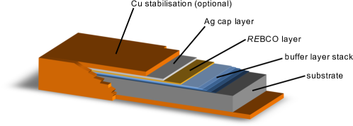
Rare-earth-barium-copper oxide tapes are layered conductors. By chemical or physical means, layers of metal oxides (buffer layers), a superconducting REBCO layer and stabilizing silver and copper layer are deposited with a two dimensional texture upon a substrate of structural material (usually Hastelloy®, stainless steel or nickel alloys). Due to this type of manufacturing, REBCO tapes are often referred to as coated conductors. Their layout is shown schematically in figure 1.
In this work, we measured the electro-mechanical properties of REBCO tapes using a Walters spring [30, 31], combining high sample lengths with the possibility to measure in tension and in compression. This method however requires the samples to be soldered to the spring, pre-straining them upon cool-down and thus making a determination of their zero strain value necessary. Compared to the other low temperature superconductors, there are significant differences when performing Walters spring measurements on REBCO tapes. The below mentioned solutions are verified and utilized within this work.
2.1 Mounting of the samples
The sample has to be soldered to the spring in order to transfer the mechanical strain. With low temperature superconductors, this is commonly done with Sn50Pb32Cd18 solder (melting point of ) using a soldering iron at and heaters ( set-point) attached to the spring. With this setup, the heat transferred from the soldering iron through the sample is sufficient to locally heat the spring above the solder’s melting point in order to bond the sample [32].
- Challenges with REBCO tapes:
-
REBCO coated conductors however exhibit very low transverse thermal conductivity [33, chap. 4.3.4] (roughly three orders of magnitude lower than in tape direction [34, 35]) requiring higher soldering iron temperatures and leading to temperatures on the coated conductor surface. At these temperatures, the oxygen content in the superconducting layer is reduced, resulting in a degradation of the current carrying capabilities [36]. As the soldering is done by hand, along the length of the long sample, the temperatures and the exposure times vary. Therefore, the critical current degradation also varies along the length, yielding very inhomogeneous samples and preventing precise measurements. REBCO coated conductors thus require a different mounting method.
- Solution for REBCO tapes:
-
As it is necessary for the soldering of the sample to heat the spring above the melting point of the solder, significant heat input is required. In order to prevent the sample’s current carrying capabilities from becoming inhomogeneous during mounting, the temperature and exposure times have to be constant along the length of the coated conductor sample. This is achieved with a two step approach: in the first step, the spring and the REBCO tape sample are coated with Sn50Pb32Cd18 solder (melting point of , containing a colophony base flux core). The Walters spring is nickel coated and can be easily coated with solder by using stainless steel flux. By attaching the REBCO tape vertically to a surface with low thermal conductivity and using a soldering iron at , the soldering is quick and without any critical current degradation. The REBCO sample is then wound around the spring, coated side inwards. Two pieces of adhesive tape keep the sample in place. In the second step, the sample and the spring are put into a vacuum furnace and heated to for . The heat treatment in the vacuum furnace reduces the sample’s critical current. The reduction however is homogeneous along the length of the sample. The reduction depends on the length of the heat treatment, normalized critical currents are therefore used in all following investigations. An impact of the heat treatment on the sample’s electro-mechanical properties is investigated in subsection 3.5.
2.2 Determination of zero strain
As the samples are soldered to the spring, they follow the spring’s thermal expansion upon cool-down. The thermal expansion mismatch between the spring (in our case titanium-aluminum-vanadium Ti-6Al-4V) and the sample, induces pre-strain which has to be determined and subtracted. With an LTS sample this is done in a two step procedure. In a first step the sample is soldered at the spring’s ends while the rest of the sample remains “free” it follows its own thermal expansion during cool-down and is without pre-strain [37]. The sample’s critical current is now determined at a magnetic field and temperature at which the measurements is to take place. In a second step, the soldering of the sample is completed, connecting it fully to the spring. The sample’s current carrying capabilities are measured at the previously used temperature and field values, while slowly turning the spring until the same critical current is obtained. This position of the spring corresponds to the sample’s pre-strain and is usually referred to as its zero applied strain value. For low temperature superconductors, especially for Nb3Sn, the variation of critical current with strain, the “strain effect” is very pronounced, making this method precise and reliable. Critical currents from different fields can be used in order to further enhance the accuracy.
- Challenges with REBCO tapes:
-
For REBCO coated conductors on the other hand, the strain effect is significantly lower compared with low temperature superconductors. Within the reversible region, mechanical strains reduce the current carrying capabilities solely by a few percent, preventing precise determination of the zero strain with the above mentioned procedure. Electro-mechanical Walters spring measurements with REBCO tapes require therefore a different mean to obtain their point of zero strain.
- Solution for REBCO tapes:
-
The use of two strain gauges, one glued onto the sample and one glued to a free piece of REBCO tape located close to the spring, enables direct measurement of the strain induced into the sample during cool-down [29, 24]. strain gauges are used that are fed with a constant current of in series with a high precision current source and are read in parallel with two Nano-volt meters. The readout of the Nano-volt meters is zeroed at room temperature, the probe is inserted into the cryostat and cooled down to measurement temperature (, respectively). The readouts diverge as the strain gauge onto the free piece of REBCO tape follows the coated conductor’s thermal expansion while the strain gauge on the sample is mainly influenced by the thermal expansion of the spring material. With at and at , the thermal expansion of the spring (Ti-6Al-4V) is very low, much lower than the coated conductors’ thermal expansion [13]. The REBCO tapes samples are therefore strained in tensile direction. Slowly turning the spring into compression reduces the differences of the strain gauges’ readouts until they are equalized around to strain depending on the manufacturer of the coated conductor sample. This is the zero strain value of the sample at the used measurement temperature. With repeated measurements of the same type of coated conductor sample, this method has proven to be precise, reliable and repeatable. Furthermore, using the temperature dependent gauge factor of the strain gauges, it is possible to use the sample’s gauge to directly calibrate the angle and applied strain correlation of the Walters spring. This method to determine the zero strain value is used in all following experiments.
3 Experimental details
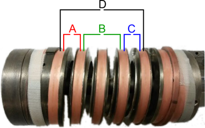
A four-turn, titanium-vanadium-aluminum (Ti-6Al-4V) Walters spring with an active diameter of is used. There is a wide grove for the sample. The total length of the sample is , there are of the sample on the spring usable for measurements. The Walters spring and the mounted sample are shown in figure 2.
3.1 Determination of the critical current
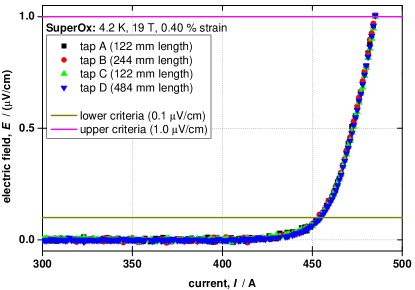
Four pair of voltage taps are used to determine the samples’ critical current. One pair of voltage taps over the first turn (A: measurement length) , one pair over the second and third turns (B: measurement length) and one pair over the fourth turn (C: measurement length). The final pair of voltage taps is over the whole spring (D: measurement length). During the measurement, the current is increased in small steps while four Nano-volt meters simultaneously read the voltage over the different turns of the sample. This arrangement allows low noise measurements for precise determination of the critical currents and the critical current index values (n-values). An exemplary electric field vs. current curve, demonstrating the precision of the system, is shown in figure 3. In all following experiments, the critical current is defined as the current at the critical electric field of (lower criteria) of the voltage tap pair spanning the whole spring (D: of measurement length).
3.2 Determination of the strain dependence of the critical current
If the superconducting layer is not located in the sample’s center, strain is induced while bending around the spring. The bending strain depends on the displacement of the superconducting layer from the tape’s neutral axis and is determined by comparing the circumference of the neutral axis and the circumference of the REBCO layer. In all investigated samples, the superconducting layer is located closer to the center of the spring compared with the sample’s neutral axis, the superconducting layer is therefore compressed upon bending around the spring. The sample’s strain is obtained by subtracting the zero strain value and the bending strain from the applied strain. In order to determine the samples’ irreversibility limits (irreversible strain and irreversible stress ), after each critical current measurement at certain strain , the strain is reduced to the previous strain step and the critical current is measured again . Within the reversible strain region of the sample, the critical current recovers yielding the same value as on the first measurement at this strain . However, if the sample is damaged, this procedure is not reversible and the critical current of the “backstep” is lower than the value found at the first measurement . With this method, the irreversible strain of the sample is therefore defined as the strain interval between the highest strain step after which at least one of the backsteps recovered and first strain step with no recovering backsteps. This interval is converted into a stress interval using the stress and strain correlation of the corresponding sample (subsection 4.2) yielding the irreversible stress limit . All following experiments utilize this method to determine the samples’ irreversibility limits.
3.3 Determination of the stress dependence of the critical current
In order to translate the strain behavior of the coated conductors to stress, their stress - strain correlation is measured at the same temperatures of the electro-mechanical tests using a free standing mechanical measurement system. One side of the sample is fixed while the other is attached to a pulling rod. Nyilas type extensometers [38, 39] are attached to the sample reading the strain while a high precision load cell located in the pulling rod directly above the sample reads the stress. After cool-down to operating temperature, the sample is slowly strained, releasing the force to two thirds of its current value at and strain. The slope of these so called “mini loops” give the sample’s Young’s modulus . For the determination of the stress, the cross sectional area of the sample is highly important, thus the precise dimensions of the coated conductor sample are obtained through micro-graphs. The stress versus strain curves are fitted with high order polynomial functions in order to translate the measured strains of the Walters spring experiments into mechanical stresses.
3.4 Investigated samples
In this work, REBCO coated conductors from the major industrial manufacturers Bruker HST, Fujikura, SuNAM, SuperOx and SuperPower are characterized. An overview of the investigated samples including their strain corrections, zero strains and bending strains is given in table 1.
| Bruker HST | Fujikura | SuNAM | SuperOx | SuperPower | |
| width | |||||
| thickness | |||||
| substrate | stainless steel | Hastelloy | Hastelloy | Hastelloy | Hastelloy |
| Cu stabilization | electroplated | laminated | electroplated | electroplated | electroplated |
| * | * | * | |||
3.5 Impact of the heat treatment on the electro-mechanical properties
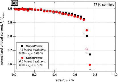
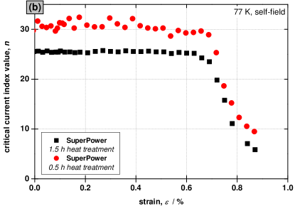
As the samples are heated in a vacuum furnace to during mounting, their superconducting layers are partially depleted of oxygen with the level of depletion depending on the duration of the heat treatment. In order to investigate the influence of the oxygen depletion on the electro-mechanical properties, two samples of the same REBCO tapes are mounted using two different heat treatment times (long heat treatment of and short heat treatment of ) . Their electro-mechanical properties are measured in a liquid nitrogen bath at , self-field. The strain dependence of their normalized critical current as well as their irreversible strain limits are shown in graph (a) of figure 4 while graph (b) gives the strain dependence of their critical current index values (n-values) . Both samples behave identically, their normalized critical current versus strain curves overlap and their reversible strain limits are within for the long heat treatment and within for the short heat treatment. This is within one step of strain () as used for these measurements. The critical current index value (n-value) versus strain curves are of the same shape, with higher n-values in the case of the shorter heat treatment. This is to be expected as the oxygen depletion of this sample is lower, resulting in higher critical currents and therefore also higher n-values due to the strong correlation between pinning properties, critical current and n-value. Furthermore, these measurements demonstrate the reliability and repeatability of the Walters spring setup, and show that any major impact of the heat treatment on the electro-mechanical properties of the REBCO tape samples can be excluded.
4 Results
With the above mentioned setup and measurement procedure, all REBCO tape samples (SuperPower, Bruker HTS, SuNAM, Fujikura and SuperOx) are electro-mechanically characterized at , self-field and , . The magnetic field is oriented parallel to the tape surface. All samples have been subjected to the same heat treatment during mounting ( at ). Their strain behavior (subsection 4.1) is combined with stress-strain measurements at the same temperatures (subsection 4.2) in order to gain the samples’ stress behavior (subsection 4.3). To ease the comparison of the results for the various manufacturers and due to the critical current degradation during their heat treatments, the current carrying capabilities of all coated conductor samples are normalized to their maximal critical current.
4.1 Normalized critical current vs. strain
The , self-field strain dependence of the samples is shown in figure 5 with the normalized critical current versus strain dependence in graph (a) and the n-value dependence in graph (b).
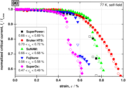
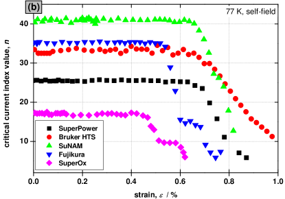
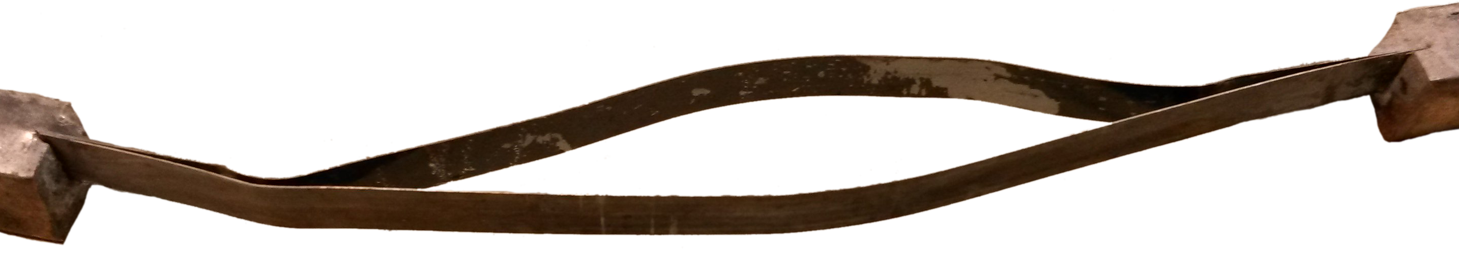
The tapes from SuperPower and SuNAM exhibit very similar strain dependence with irreversible strain limits of for SuperPower tapes and for SuNAM tapes. Their normalized critical current curves overlap and their n-value curves are of similar shape with higher n-values for the SuNAM tapes. Bruker HTS tapes exhibit a “more round” normalized versus critical current curve, indicating a stronger strain effect accompanied by very high irreversible strain limits of . The samples from Fujikura and SuperOx on the other hand have a “step-like” transition from their reversible to irreversible region. At a rather low strain ( for Fujikura tapes and for SuperOx tapes), their critical current is irreversibly reduced and stabilized at lower currents. At higher strains, there is a second strong degradation of their current carrying capabilities. This “step-like” behavior is also visible in the n-value versus strain dependence in graph (b). At , self-field the samples with the highest irreversible strain limits are from Bruker HTS, followed by SuperPower and SuNAM. The irreversible strain limits of Fujikura and SuperOx are significantly lower due to the “step-like” transition. Furthermore, the samples from Fujikura and SuperOx are fully de-laminated after these measurements as shown in figure 6. The tapes are split between the buffer layer stack and the superconducting REBCO layer. This behavior is not observed for any other type of coated conductor tapes. The de-lamination and the step like behavior may indicated a interfacial weakness of Fujikura and SuperOx coated conductor tapes.

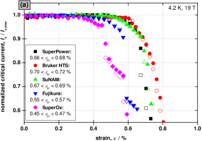
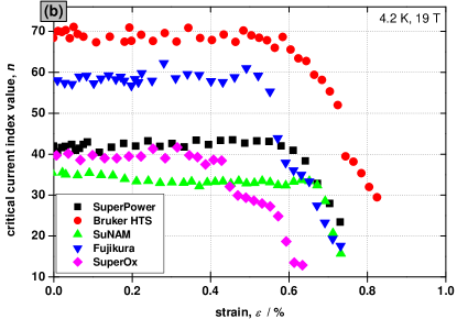
Similar behavior of the coated conductor samples is observed at , as shown in figure 7; normalized critical current versus strain in graph (a) and n-value versus strain in graph (b). In the samples’ reversible region, the strain dependence of the normalized critical current is lower, the transition to irreversibility however is steeper. The samples’ irreversible strain limits are similar; highest for Bruker HTS tapes with , followed by SuNAM with and SuperPower with . Fujikura and SuperOx REBCO tapes exhibit significantly lower irreversible strain limits with and , respectively. Full de-lamination of Fujikura and SuperOx tapes is observed again. An impact of the mounting procedure cannot be excluded as during the heat treatment the tapes are exposed to temperatures above the manufacturers’ recommendations.
4.2 Stress - strain correlation
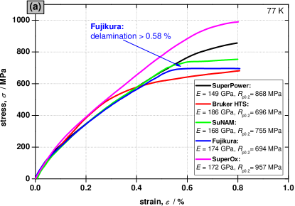
As described in subsection 3.3, the samples’ correlation of applied strain and mechanical stress is measured at and . The data is shown in graph (a) of figure 8 and the data in graph (b). For the sake of readability, all “mini loops” (partial release of the stress at certain strains) have been removed from the graphs. Young’s moduli are obtained at the “mini loops” performed at strain. The highest Young’s modulus and yield strength are encountered for the tape from SuperOx, followed by SuperPower and SuNAM. With its stainless steel substrate, the stress - strain curve of the Bruker HTS tapes is more “round” resulting in the poorest mechanical properties. For the other manufacturers, the differences are mainly due to varying copper - Hastelloy ratios. Comparing and , all sample’s mechanical properties are very similar: their Young’s modulus are identical at both temperatures while their mechanical yield strengths are roughly higher at . All samples’ stress-strain relations are slightly nonlinear even at low strains. There are no distinct elastic and inelastic regimes visible as a significant fraction of all samples, the copper, is already in yielding solely due to the cool-down to cryogenic temperatures [40].
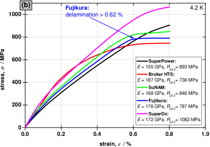
The Fujikura samples fully de-laminate during the stress - strain measurements as shown in figure 9. At the de-lamination occurs above and above at . On the whole length, the samples are split between the buffer layer stack and the superconducting layer indicating again a weakness of the interface between these layers in the coated conductors from Fujikura. No de-lamination is observed the other manufacturers’ tapes during the stress - strain measurements. In the stress - stain measurements, all samples are as received without heat treatment, therefore any influence of the mounting can be excluded.
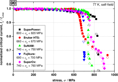
4.3 Normalized critical current vs. stress
Combining the strain dependent current carrying capabilities (subsection 4.1) with the samples’ stress - strain correlation (subsection 4.2) yields their normalized critical current versus mechanical stress. The , self-field stress dependence is shown in graph (a) of figure 10 and the , stress dependence in graph (b). The differences between the samples are lower in stress than in strain, as the tapes from Bruker HTS which exhibit high irreversible strain have low mechanical properties due to their stainless steel substrate, leading to lower irreversible stress ( of at and at ). The high mechanical strength of Hastelloy results in high irreversible stress limits even for the tapes with low irreversible strain ( of , at and , at for Fujikura respectively SuperOx tapes). This brings the irreversible stress limits of all investigated REBCO tapes close together, especially at where all irreversible limits are within the range.

5 Discussion and conclusion
The strain dependence of the tapes’ normalized current carrying capabilities shows strong differences between the manufacturers. The irreversible strain limits range from for SuperOx tapes to for Bruker HTS tapes. Due to similar conductor layouts, the strain dependencies of tapes from SuperPower and SuNAM are close, with irreversible strain limits of . Fujikura and SuperOx tapes de-laminate during the electro-mechanical measurements, resulting in a step like transition to irreversibility and in lower irreversible strain limits. Neither de-lamination nor such a step like transition is observed for any other manufacturer. All samples were heated to temperatures above the manufacturers’ recommendations during mounting, an impact of this heat treatment cannot be excluded. Comparing , self-field and , , the irreversible strain limits of all samples are identical while the strain effect (the reversible reduction of the critical current) is significantly lower at low temperature and high field. Remaining below strain, there are no discernible differences in the samples’ strain dependencies within the measurement accuracy. These results are in good agreement with free-standing critical current versus strain measurements which yield irreversible stress-limits of different commercial conductors in the range [41, 42, 43]. In a second step, the samples’ mechanical properties are investigated at and at . From the comparison of the results at these two temperatures, we found for all the tapes that the Young’s modulus does not vary but the yield strengths is ca. higher at the lower temperature. Young’s moduli are in the range, highest for Bruker HTS and lowest for SuperPower. All samples’ curves are nonlinear even at low strains due to the significant fraction of copper which is always in yielding solely from the cool-down to cryogenic temperatures [40, p. 2-15]. Bruker HTS’s curve is more round compared with the other samples because of its stainless steel substrate making it the sample with the lowest yield strength (ca. ). With ca. , the highest yield strength is observed for the REBCO tapes from SuperOx mainly due to its strong Hastelloy substrate and low copper cross section area. Full de-lamination is observed again with Fujikura REBCO tapes during the mechanical measurements the sample are as received without any heat treatment, thus indicating an interfacial (buffer layer stack to REBCO layer) weakness. In a third step, the WASP measurements are combined with the samples mechanical properties yielding the samples’ dependence of their reduced critical current on applied stress. While the investigated coated conductor tapes are very different in their irreversible strain limits, their irreversible stress behavior is much more similar. Especially at , , stresses have almost no effect on the current carrying capabilities within the reversible region and the irreversible stress limits of all samples are in the range. The irreversible stress limits are lowest for Bruker HTS due its “round” stress - strain correlation combined with a low yield strength and highest for SuperPower. Below , there are no differences in the samples’ strain dependencies of their critical currents. All mechanical and electro-mechanical properties of the investigated REBCO tapes are summarized in table 2 at , self-field and , .
| , self-field | Young’s modulus, | yield strength, | irreversible strain limit, | irreversible stress limit, |
|---|---|---|---|---|
| Bruker HTS | ||||
| Fujikura | ||||
| SuNAM | ||||
| SuperOx | ||||
| SuperPower |
| , | Young’s modulus, | yield strength, | irreversible strain limit, | irreversible stress limit, |
|---|---|---|---|---|
| Bruker HTS | ||||
| Fujikura | ||||
| SuNAM | ||||
| SuperOx | ||||
| SuperPower |
Below strain and below longitudinal tensile stress, there are no differences between the samples. On the other hand, in the case of applications where conductors are exposed to higher strains or stresses, great attention needs to be paid to the choice of the conductor. Common HTS applications are within these limits ( in Bi2223 NMR coils [8], in HTS fusion magnets [9] and in REBCO NMR coils [10]) allowing the conductor choice to be based on other properties as the transverse stress dependence, the field dependence [5], the thermal conductivity [34, 35] or the electric and the thermal stability. However, in small coils, combination of hard and soft bending at the last turn of the layer can result in strains above these limits and the strain sensitivity of the conductor becomes the limiting factor.
References
- [1] K Kasaba, K Katagiri, Y Shoji, T Takahashi, K Noto, K Goto, T Saito, and O Kono. Stress-strain dependence of critical current in Nb3Sn superconducting wires stabilized with Cu-Nb microcomposites - effect of Nb content. Cryogenics, 41(1):9–14, January 2001.
- [2] P Zhang, M Liang, X Tang, C Li, C Xiao, K Zhang, L Zhou, Y Wi, P Weng, and Y Lu. Strain influence on Jc behavior of Nb3Sn multifilamentary strands fabricated by internal tin process for ITER. Physica C: Superconductivity, 468(15-20):1843–1846, September 2008.
- [3] P Bruzzone. Review of Design Aspects for High Current Nb3Sn Conductors. Applied Superconductivity, IEEE Transactions on, 21(3):2036–2041, 2011.
- [4] J Bascuñán, S Hahn, Y Kim, J Song, and Y Iwasa. Design and Double-Pancake Coil Fabrication. IEEE Transactions on Applied Superconductivity, 24(3):4300904, 2014.
- [5] C Senatore, M Alessandrini, A Lucarelli, R Tediosi, D Uglietti, and Y Iwasa. Progresses and challenges in the development of high-field solenoidal magnets based on RE123 coated conductors. Superconductor Science and Technology, 27(10):103001, October 2014.
- [6] L Rossi, A Badel, M Bajko, A Ballarino, L Bottura, M M J Dhalle, M Durante, Ph Fazilleau, W Goldacker, E Härö, A Kario, G Kirby, C Lorin, J van Nugteren, G de Rijk, T Salmi, C Senatore, P Tixador, A Usoskin, G Volpini, Y Yang, and N Zangenberg. The EuCARD-2 Future Magnets European collaboration for accelerator quality HTS magnets. submitted for publication, IEEE Transaction on Applied Superconductivity, 2014.
- [7] P V Gade, C Barth, C M Bayer, W H Fietz, F Franza, R Heller, K Hesch, and K Weiss. Conceptual Design of a Toroidal Field Coil for a Fusion Power Plant Using High Temperature Superconductors. IEEE Transactions on Applied Superconductivity, 24(3):4202705, 2014.
- [8] T Kiyoshi, S Choi, S Matsumoto, K Zaitsu, T Hase, T Miyazaki, M Hamada, M Hosono, and H Maeda. Bi-2223 Innermost Coil for 1.03 GHz NMR Magnet. IEEE Transactions on Applied Superconductivity, 21(3):2110–2113, June 2011.
- [9] G Bansal, N Yanagi, T Hemmi, K Takahata, T Mito, and A Sagara. High-Temperature Superconducting Coil Option for the LHD-Type Fusion Energy Reactor FFHR. Plasma and Fusion Research, 3:1049, 2008.
- [10] A Otsuka, T Kiyoshi, and M Takeda. A 1.3 GHz NMR magnet design under high hoop stress condition. IEEE Transactions on Applied Superconductivity, 20:596–599, 2010.
- [11] D C van der Laan, J W Ekin, C C Clickner, and T C Stauffer. Delamination strength of YBCO coated conductors under transverse tensile stress. Superconductor Science and Technology, 20(8):765–770, August 2007.
- [12] T Takematsu, R Hu, T Takao, Y Yanagisawa, H Nakagome, D Uglietti, T Kiyoshi, M Takahashi, and H Maeda. Degradation of the performance of a YBCO-coated conductor double pancake coil due to epoxy impregnation. Physica C: Superconductivity, 470(17-18):674–677, September 2010.
- [13] C Barth, N Bagrets, K-P Weiss, C M Bayer, and T Bast. Degradation free epoxy impregnation of REBCO coils and cables. Superconductor Science and Technology, 26(5), 2013.
- [14] C C Koch and D S Easton. A review of mechanical behaviour and stress effects in hard superconductors. Cryogenics, 17(7):391–413, 1977.
- [15] J W Ekin. II-4: Stress/strain effects on critical current. Cryogenics, 35(1):25–28, 1995.
- [16] B Seeber, A Ferreira, V Abächerli, and R Flükiger. Critical current of a Nb3Sn bronze route conductor under uniaxial tensile and transverse compressive stress. Superconductor Science and Technology, 20(9):S184–S188, September 2007.
- [17] M C Jewell, T Boutboul, L-R Oberli, F Liu, Y Wu, Al Vostner, T Isono, Y Takahashi, S H Park, Al Shikov, A Vorobieva, N Martovetsky, K Seo, D Bessette, and A Devred. World-Wide Benchmarking of ITER Nb3Sn Strand Test Facilities. IEEE Transactions on Applied Superconductivity, 20(3):1500–1503, 2010.
- [18] L F Goodrich, N Cheggour, X F Lu, J D Splett, T C Stauffer, and B J Filla. Method for determining the irreversible strain limit of Nb 3 Sn wires. Superconductor Science and Technology, 24(7):075022, July 2011.
- [19] Y Iwasa. Case studies in superconducting magnets. Springer, New York, 2. edition, October 2009.
- [20] B Liu, Y Wu, and P Bruzzone. The results of the second Chinese TF conductor sample. Fusion Engineering and Design, 86(4-5):369–372, June 2011.
- [21] B Liu, Y Wu, F Long, and S Li. Test results and analyses of conductor short samples for China first PF conductor. Cryogenics, 51(2):90–94, February 2011.
- [22] N Cheggour, J W Ekin, Y-Y Xie, V Selvamanickam, C L H Thieme, and D T Verebelyi. Enhancement of the irreversible axial-strain limit of Y-Ba-Cu-O-coated conductors with the addition of a Cu layer. Applied Physics Letters, 87(21):212505, 2005.
- [23] H-S Shin, K-H Kim, J R C Dizon, TY Kim, R-K Ko, and S-S Oh. The strain effect on critical current in YBCO coated conductors with different stabilizing layers. Superconductor Science and Technology, 18(12):S364–S368, December 2005.
- [24] D Uglietti, B Seeber, V Abächerli, W L Carter, and R Flükiger. Critical currents versus applied strain for industrial Y-123 coated conductors at various temperatures and magnetic fields up to 19 T. Superconductor Science and Technology, 19(8):869–872, August 2006.
- [25] M Sugano, K Shikimachi, N Hirano, and S Nagaya. The reversible strain effect on critical current over a wide range of temperatures and magnetic fields for YBCO coated conductors. Superconductor Science and Technology, 23(8):085013, August 2010.
- [26] D C van der Laan, J W Ekin, J F Douglas, C C Clickner, T C Stauffer, and L F Goodrich. Effect of strain, magnetic field and field angle on the critical current density of YBa2Cu3O7- coated conductors. Superconductor Science and Technology, 23(7):072001, July 2010.
- [27] H-S Shin and M J Dedicatoria. Variation of the strain effect on the critical current due to external lamination in REBCO coated conductors. Superconductor Science and Technology, 25(5):054013, May 2012.
- [28] P Sunwong, J S Higgins, Y Tsui, M J Raine, and D P Hampshire. The critical current density of grain boundary channels in polycrystalline HTS and LTS superconductors in magnetic fields. Superconductor Science and Technology, 26(9):095006, September 2013.
- [29] D Uglietti, B Seeber, V Abächerli, A Pollini, D Eckert, and R Flükiger. A device for critical current versus strain measurements up to 1000 A and 17 T on 80 cm long HTS and LTS technical superconductors. Superconductor Science and Technology, 16(9):1000–1004, September 2003.
- [30] C R Walters, I M Davidson, and G E Tuck. Long sample high sensitivity critical current measurements under strain. Cryogenics, 26(7):406–412, 1986.
- [31] B Seeber, G Mondonico, and C Senatore. Toward a standard for critical current versus axial strain measurements of Nb3Sn. Superconductor Science and Technology, 25(5):054002, May 2012.
- [32] D Uglietti, B Seeber, V Abächerli, and N Banno. Critical current vs. Strain for LTS wires up to 21 T. IEEE Transactions on Applied Superconductivity, 15(2):3652 – 3655, 2005.
- [33] C Barth. High Temperature Superconductor Cable Concepts for Fusion Magnets. KIT Scientific Publishing, Karlsruhe, 1. edition, 2013.
- [34] M Bonura and C Senatore. High-field thermal transport properties of REBCO coated conductors. submitted for publication, Superconductor Science and Technology, 2014.
- [35] M Bonura and C Senatore. Transverse thermal conductivity of REBCO coated conductors. submitted for publication, IEEE Transaction on Applied Superconductivity, 2014.
- [36] H S Kim, J B Song, N Y Kwon, K L Kim, and H G Lee. The influence of heat-treatment and oxygenation annealing on the superconducting properties of YBCO coated conductors. Superconductor Science and Technology, 22(12):125016, December 2009.
- [37] B Seeber, D Uglietti, V Abächerli, P A Bovier, D Eckert, G Kübler, P Lezza, A Pollini, and R Flükiger. Critical current versus strain measurement up to and . Rev. Sci. Instrum, 76:093901, 2005.
- [38] A Nyilas. Transducers for Sub-Micron Displacement Measurements at Cryogenic Temperatures. Advances in cryogenic engineering, 824:27–34, 2005.
- [39] A Nyilas. Strain sensing systems tailored for tensile measurement of fragile wires. Superconductor Science and Technology, 18(12):S409–S415, December 2005.
- [40] P Bauer, H Rajainmaki, and E Salpietro. EFDA Material Data Compilation for Superconducting Simulation, 2007.
- [41] H S Shin, J R C Dizon, R K Ko, T H Kim, D W Ha, and S S Oh. Reversible tensile strain dependence of the critical current in YBCO coated conductor tapes. Physica C: Superconductivity, 463-465:736–741, October 2007.
- [42] H-S Shin and M J Dedicatoria. Variation of the strain effect on the critical current due to external lamination in REBCO coated conductors. Superconductor Science and Technology, 25(5):054013, May 2012.
- [43] H-S Shin and M J Dedicatoria. Intrinsic strain effect on critical current in Cu-stabilized GdBCO coated conductor tapes with different substrates. Superconductor Science and Technology, 26(5):055005, May 2013.