Verifying the correct composition of distributed components: Formalisation and Tool ††thanks: This work was partialy funded by the Associated Team DAESD between INRIA and ECNU, Shanghai; and by the french Fond National pour la Société Numérique project OpenCloudware.
Abstract
This article provides formal definitions characterizing well-formed composition of components in order to guarantee their safe deployment and execution. Our work focuses on the structural aspects of component composition; it puts together most of the concepts common to many component models, but never formalized as a whole. Our formalization characterizes correct component architectures made of functional and non-functional aspects, both structured as component assemblies. Interceptor chains can be used for a safe and controlled interaction between the two aspects. Our well-formed components guarantee a set of properties ensuring that the deployed component system has a correct architecture and can run safely. Finally, those definitions constitute the formal basis for our Eclipse-based environment for the development and specification of component-based applications.
1 Introduction
Designing safe distributed component-based software systems is a challenging task including a wide range of issues ranging from the safe composition of components to the applications performance and reliability. This work focuses on the correctness of component assembly which is a strong prerequisite for correct deployment and execution of components. We target component models which are hierarchical [14] and provide runtime control on the component application. In component-based software engineering, this last feature, i.e. the control and management of the system architecture and of the business application, is part of what is generally called non-functional concern. More precisely, non-functional aspects may cover many aspects, from security, latency, time aspects, energy or cost, to management concerns including mechanisms for dynamic reconfiguration, fault-tolerance, load balancing, self-healing, or more elaborate autonomic behaviours. In this paper, we are essentialy considering the second category, i.e. the management aspects, and we want to support the ability to design non-functional aspects themselves as a component system, which ensures a clear design of the whole application. The business logic of the application is called the functional aspect.
Our main goal is to provide a clear and formal definition of component assemblies and a set of logic predicates ensuring the correctness of component composition and component interconnection. In particular our predicates ensure a strong separation of concerns: a non-functional component can only interact with non-functional components, or with non-functional interfaces of business components. This way, each binding between components only transmits either functional or non-functional invocations. However a clean interaction between these concerns is highly desirable: we introduce interceptors, which are special components providing interaction between functional and non-functional elements. They can observe functional invocations and trigger a reaction of the control part of the component. In the other direction, non-functional components can influence the functional behavior by modifying its behaviour in two ways: either through reconfiguration, i.e. modification at runtime of the component architecture, or by changing parameters, i.e. component attributes, that will influence the functional behaviour.
In this paper we focus on one specific component model: the Grid Component Model (GCM) [5]. GCM allows the construction of distributed hierarchical applications with asynchronous group communications and strong separation between business logic and control parts of a system. To our knowledge, GCM is one of the only established component models that provides specific features for managing complex software systems, and that offers architectural artifacts and methodological approaches to organise the control part of such applications. GCM-based systems can be designed and modeled using the VerCors tool111The VERCORS platform: VERification of models for distributed communicating COmponants, with safety and Security. http://team.inria.fr/scale/software/vercors/; An XML-based Architecture Description Language (ADL) file, describing the architecture of the application, can then be generated by VerCors and used to build and deploy the GCM application, using the GCM/ProActive execution environment [6]. We started from the formal representation of GCM architecture given in [3] and introduced a number of important concepts. This article has the following new contributions:
-
•
First, we provide a formal representation of component architectures including a flexible set of constructs for the definition of non-functional part of an application which has never been formalized before. The business logic and control parts of a system are strongly separated.
-
•
Second, we formalize the notion of interceptors and define a number of auxiliary predicates insuring their safe composition with the rest of the system.
-
•
Third, we specify a set of key properties for component architecture, those properties are guaranteed for any component assembly that is well-formed according to the rules defined in Section 3.4. After validation of these rules, we garantee that the generated ADL code is correct, in the sense that building the component-based application by running the GCM component factory will terminate successfully with no runtime error. Additionally, the properties we exhibit are necessary prerequisite for the correct execution and the reconfigurability of the system; those properties include uniqueness of naming, separation of concerns, and communication determinacy.
-
•
Finally, we implement an environment allowing graphical modeling and validity check for the distributed systems architecture with respect to the proposed formalization.
The purpose of our formalization is threefold. First it is component model independent: by formalizing the correctness rules, we make them applicable outside the scope of GCM, and of our tools. Second, it makes it easier to re-use the formalization for different purposes, e.g. to implement different checkers, or encode it in a theorem prover. Finally, it allows reasoning on the properties ensured by the component model: properties of Section 3.5 can be formally proven from the definition of component correctness.
This paper is organized as follows. Section 2 describes the Grid Component Model and our modeling platform. Section 3 presents the formalization of GCM architecture and of correct architecture. Section 4 describes how to adapt our formalism to other features or other component models and presents an overview of the related work. Section 5 describes our environment for modeling GCM-based systems.
2 Context
2.1 GCM
GCM [5] is a component model targeting large-scale distributed applications. It is an extension of the Fractal [8] component model; we summarize below the architectural aspects of GCM, and its main advantages. We also provide an illustrative example of a real-world application built using GCM.
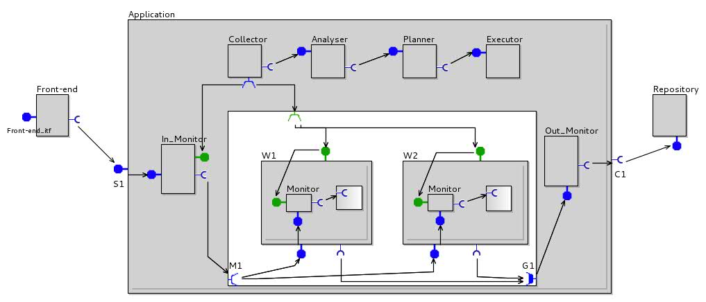
A GCM component application is a composition of components, interfaces and bindings. GCM is a hierarchical component model, consequently there are two types of components in GCM: primitive and composite ones. Composite components are used to compose other components while the primitive ones are the leaves of the composition hierarchy. More precisely, a composite component (Application in Figure 1) is made of two parts: membrane (gray part) and content (white part). The content contains the sub-components dealing with the functional aspects. The membrane includes sub-components which are responsible for everything besides business logic: control, monitoring, structural reconfiguration, etc. A primitive component is similar except that the content is not known (e.g., Front-end, Repository and W1 in Figure 1). It encapsulates some business code. It has a list of methods, which it can execute.
The communication between components is performed in the form of method invocation. In Fractal and GCM interfaces are similar to object interfaces characterized by a set of methods that can transit through this interface. There are client and server interfaces. Client interfaces (e.g. C1) emit the methods invocations. Server interfaces (e.g. S1) receive them. We also distinguish the interfaces dealing with the business logic (functional interfaces drawn in blue color) and the ones dealing with the control of an application (non-functional ones colored in green). A binding is an arrow from a client to a server interface, communications between components follow those bindings.
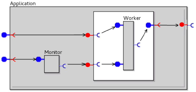
In GCM, the interfaces can be attached to the components. An interface that is accessible from the exterior of a component is called an external interfaces (e.g. S1). When an interface is reachable from the inside of a component, i.e. from its content, it is called an internal interfaces (e.g. M1). The membrane of a component can also have internal interfaces, but they are not declared explicitly. The set of internal interfaces of a membrane is represented by the union of two other sets: all the external interfaces of the component containing the membrane and all the internal interfaces of the content inside the component. All the interfaces are taken with the same properties, but with an opposite role (e.g. a server interface becomes a client one and vice-verse). Figure 2 illustrates the (implicite) internal interfaces of a membrane, displayed in red color.
Figure 1 shows an illustrative example taken from [6]. It represents the architecture of a real-world GCM system implementing an autonomic master-slave application treating incoming requests in parallel. Component Front-end is a front-end of the application. It receives the job-requests from the user. The requests are, then, processed by the workers (W1 and W2). The results are sent to the repository represented by a component Repository. The application reconfigures itself autonomically: the workers are added or removed depending on the system workload. This is realized by the sequence of components: Collector, Analyser, Planner, and Executor. This sequence follows the principle of the MAPE model for autonomic computing. The Monitoring components (Monitor, In_Monitor) in the membranes of the workers and in Application monitor different metrics such as served requests per minute, and available disk space, CPU, and memory. Component Collector gathers the information from the Monitoring components. It sends the information to the component Analyser. Based on the received information, Analyser sends an alarm to the Planning component (Planner). The former one plans the reconfiguration, which is enacted by the Execution component (Executor).
GCM provides the following features to the applications:
- Strong separation of concerns
-
The functional part of a GCM application can be separated from the control part thanks to the separation of a composite component into a membrane and a content and to the usage of functional and non-functional interfaces. In the provided example, the components performing the reconfiguration (Collector, Analyser, Planner, Executor) are separated from the ones responsible for the business logic (W1, W2, Repository). This separation ensures, as much as possible, the independence of the business code – the request treatment in the example – from the management code – the sequence of control components in the example.
- Reconfiguration
-
In GCM, the architecture of the application can be accessed and modified at runtime; this is realized in the example by the execution component. It allows the non-functional concern to modify the structure of the functional (and the non-functional) part of the component application, and thus to change its behavior.
- Interceptors
-
Sometimes, some information should be shared between the functional part and the controllers of the application. Interceptors are specific components inside the membrane that can intercept the flow of functional calls in order to trigger reaction from the non-functional aspects. For example, in the use-case, Monitor components are monitoring the number of job-requests sent to the worker, they illustrate very well what is an interceptor. In the membrane, functional interfaces are directly connected, however one or several interceptors can be inserted within such a binding and interact with other non-functional components (see the non-functional binding between Monitor and Collector in the example).
- One-to-many / many-to-one communications
-
GCM also targets large-scale distributed systems where an invocation is to be broadcast to several entities or simply sent to different servers to ensure load-balancing. For this, GCM introduces one-to-many client interfaces, called multicast interfaces like the interface M1 of Figure 1. From a structural point of view the particularity of multicast interfaces is that they can be connected to several server interfaces. Symmetrically, GCM introduce gathercast server interfaces for synchronizing many-to-one communications, typically waiting for a number of communications before triggering a communication.
Our main contribution here is a formal definition and specification of the non-functional aspects of components; we will also see how we formally insure the separation of concerns and how we formally specify the interceptors.
2.2 VerCors
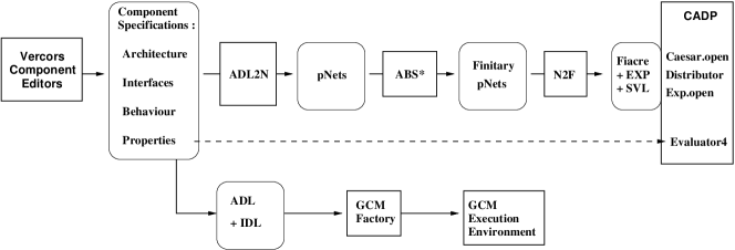
VerCors is a platform for the specification, analysis, verification, and validation of the GCM-based applications. The principle of the tool is illustrated in Figure 3. First, a user specifies the architecture of a GCM-based application, the signature of its interfaces, and the behavior of the primitive components using VerCors Component Editor (VCE). Then, from these descriptions the behavioral model of an application is generated (ADL2N) in a form of a dedicated behavioral semantic model: a parameterized networks of synchronized automata (pNets). This semantic model is transformed by abstraction functions (ABS*), until reaching a finite model suitable for model-checking. Finally, the resulting behavioral model is translated (N2F) into a set of languages used by a Model Checker (CADP tool [11]). Finally, the Model Checker verifies the correctness of the model with respect to a set of temporal logic properties (user requirements) and in the case of detected errors it provides their description.
Once the requirements have been proven correct on the VCE specification, the user can generate the set of files (ADL for the Architecture Description, IDL for the Interface definition in the form of Java interfaces). Then naturally, user has to provide java classes implementing the service methods of the primitive components. These files are processed by the GCM component factory to build an executable application, that is executed with the GCM/ProActive execution environment.
In this paper we focus only on the structural aspect of GCM-based applications which is covered by the VerCors Component Editor. Our purpose is to ensure that the components provided to the rest of the tool chain are well-formed; for this we describe below a set of rules that must be satisfied to ensure the correctness of a GCM component assembly, we describe their implementation in VCE in Section 5.
Using VerCors tool, we were able to design the architecture of the example illustrated at Figure 1, check its static semantic correctness properties, generate ADL files and deploy the corresponding application.
3 Formalization
The purpose of this section is to define formally well-formed components and exhibit their properties.
| Element | Formalization |
|---|---|
| Server interface | |
| Client interface | |
| Interface | |
| Method signature | |
| Primitive | |
| Composite | |
| Component | |
| Content | |
| Binding |
|
| Nature | |
| Membrane |
3.1 Structure
We start with the formal model representing the GCM architecture. First, we discuss the core elements. Second, we formalize the non-functional part of the GCM architecture.
3.1.1 Core
In this section we define the core elements of GCM, namely: Interfaces, Components and Bindings. Their formalization is given in Table 1. We denote a set of elements indexed in a set . The formal definition is not provided for some elements of the table, because they are the terminal symbols. Such elements are presented in different font (e.g. Name, Type, NF).
Each server (SItf) or client (CItf) interface is characterized by three attributes: Name is the name of an interface; MSignatures represent the methods which can be served by a server interface or called by a client interface, with their signature; Nature defines if it is a functional or a non-functional interface.
Each component is characterized by its name, the sets of external client and server interfaces, and its membrane. A primitive component also includes a set of local methods. A composite component includes its content with a specific structure. The membrane is responsible for the non-functional activity. The content is defined by the sets of internal client and server interface, sub-components and a set of bindings located inside the content.
A binding connects two interfaces. It is described as a couple of names defining its source and target interfaces. Each name consists of two parts. The first part describes the container of the interface, either the name of a sub-component or the identifier This. The second part is the name of the interface itself.
3.1.2 Non-functional aspects
The property of interfaces can be either functional (F) or non-functional (NF). The membrane is the part of a component which is responsible for the non-functional aspect of an application. Its formalization is given in the bottom of Table 1. The bindings () are the connections between the interfaces in the membrane. A membrane can contain a set of sub-components (). The interceptors are recognized in this set essentially from their binding patterns, all the other components in a membrane are simple controllers.
3.2 Auxiliary functions
In this section we introduce the auxiliary functions used for the GCM architecture well-formness formalization. The auxiliary functions are given in Table 2.
| Function name | Function Definition |
|---|---|
| Sym | |
| Itf |
|
| GetSrc |
|
| GetDst |
|
| Parent |
First, we use auxiliary functions providing the access to the attributes of the interfaces and components. For example, the function returns the nature of an interface, returns the set of bindings in a membrane. The definitions of such functions are straightforward and we omit them in Table 2.
Second, the symmetry function () takes an interface as an input and returns an interface with exactly the same properties but with an opposite role: a client interface becomes a server one and symmetrically. to
Third, we introduce a GetItf function. It takes a container (a component, a membrane or a content) as an input and computes the set of interfaces stored by it. If its argument is a component or a content, then its result is the union of its server and client interfaces sets. The case of membrane is more complicated as its internal interfaces are not explicitly defined. Instead, we compute the set of the symmetric of the interfaces belonging to the component containing the membrane and its content.
Finally, most of the consistency rules dealing with the bindings will use the auxiliary functions and . They are able to retrieve the Interface objects which represent respectively the source and the destination ends of a binding. If and functions are applied to a binding inside a membrane, then they may return an internal interface of the membrane.
Conversely, some rules use the auxiliary function, that recovers the container (component, membrane or content) of an interface, a component, a content or a membrane.
3.3 Interceptors
In this section we define interceptors more precisely. First, we provide the non-formal definition of an interceptor. Then, we introduce a predicate recognizing the interceptors among the other sub-components of a membrane.
An interceptor is a functional component inside a membrane. It is connected to one external and one internal functional interfaces of the membrane’s parent. An interceptor ”intercepts” a functional call that goes from outside to inside of the membrane (input interceptor) or vice versa (output interceptors). The interceptors are used to monitor an application and its functional calls. The only functional activity of an interceptor should be to intercept and forward the functional calls through its functional client and server interfaces. All the other actions are performed through non-functional interfaces. To allow more modularity in the design, interceptors can be assembled in chains inside the membrane. Interceptors in a chain must all be either input or all output; we shall speak of input chains and output chains.
In principle, it would be possible to relax this definition, and allow for more general interceptor structures, e.g. including some parallelism in the form of multicast client interface in the “chain”, allowing more efficient processing. However it is not clear whether this would be useful fo rreal applications, and this not implemeted in the GCM/ProActive middleware, so we prefer to keep the (relatively) simpler form in the formal definition.
In order to distinguish formally the interceptors from the other components, we define a predicate IsInterc. It is given in Table3. It takes a component and a membrane as an input and returns if the component belongs to a chain of interceptors inside the given membrane. An interceptor chain consist of one or several interceptors. IsInterc uses a predicate IsIntercChain which identifies if a given sequence of components is a chain of pipelined interceptors inside the given membrane. predicate checks the following features of the indexed set of components given as input:
-
•
all the components are nested inside the membrane;
-
•
all the components have exactly one functional server and one functional client interface;
-
•
a functional call can go through the sequence of components. More formally, for any there is a binding connecting client functional interface of the component number and server functional interface of the component number ;
-
•
the first component of an input chain intercepts a functional call to the content while the last component forwards the functional call to the content or vice versa for an output chain.
Predicate IsIntercChain uses two auxiliary functions: (resp. ) returns the sets of all functional server (resp. client) interfaces of component comp.
The predicate IsExtEnd checks, for an input interceptor chain, whether the first interceptor in the chain is connected to a server functional interface of the parent component or, for output interceptors, whether the last one is connected to a client functional interface of the parent component. Predicate IsIntEnd is the symmetric, it checks connection with the content. However, the content is not known for a primitive component; in that case the interfaces of the content are computed by symmetry of the external (functional) interfaces of the component.
| Predicate name | Predicate Definition |
|---|---|
| IsInterc |
|
| IsIntercChain |
|
| IsExtEnd |
|
| IsIntEnd |
|
3.4 Well-formed components
In this section we define the well-formness rules for GCM components. First, we introduce the core rules and predicates used for the definition of well-formness. Then, we focus on the non-functional aspects.
| Predicate name | Predicate Definition |
|---|---|
| UniqueCompNames |
|
| UniqueItfNames |
|
| BindingRoles |
|
| BindingTypes |
|
| CardValidity |
|
3.4.1 Core
Table 4 formalizes the auxiliary predicates which are used for the definition of the following constraints:
-
•
Components naming constraint (): all the components at the same level of hierarchy must have different names. This restriction is due the fact that components are referenced by their name; typically, QName can be of the form ; and if two components had the same name the functions GetSrc and GetDst would not return a single deterministic result. The two contents of two different composite components as well as two membranes are considered to be different name-spaces. A membrane and a content are also different name-spaces even if they belong to the same component.
-
•
Interfaces naming constraint (UniqueItfNames): all the interfaces of a component must have different names. This constraint will be checked separately, for the external interfaces of a component, and for the internal interfaces of a content. This constraint also ensures the determinacy of the functions GetSrc and GetDst.
-
•
Role constraint (): a binding must go from a client interface to a server interface. The predicate uses a function that returns C (resp. S) if is a client (resp. server) interface.
-
•
Typing constraint (): a binding must bind interfaces of compatible types. The compatibility of interfaces means that for each method of a client interface there must exist an adequate corresponding method in the server interface. In other words, if a client interfaces is connected to a server interface and it wants to call some method, then this method must actually exist on the server interface. In general, a corresponding method does not need to have exactly the same signature as the one required, but can use any sub-typing or inheritance pre-order available in the modeling language. We denote such an order between interface signatures.
-
•
Cardinality constraint, , ensures that a client interface is bound to a single server one.
We use the previous constraints to define a well-formness predicate, denoted . It is defined recursively on component architecture, namely on primitive components, on composite components, and on contents.
A GCM primitive component is well-formed if all its interfaces have distinct names and its membrane is well-formed.
| (1) | |||
A GCM composite component is well-formed if all its external interfaces have distinct names, its content and its membrane are well-formed.
| (2) | |||
The content of a GCM component is well-formed if all its interfaces have distinct names, all its sub-components have distinct names, all its nested bindings ensure valid cardinality, all its sub-components are well-formed, the role, type and nature constraints are respected for all its sub-bindings. The nature constraint for the bindings relies on The predicates. It is discussed in Section 3.4.2 because it is related to the non-functional aspect.
| (3) | |||
| (7) |
The well-formness of a membrane is only significant for the non-functional aspect, it is defined below.
3.4.2 Non-functional aspects
| Predicate name | Predicate Definition |
|---|---|
| UniqueNamesAndRoles |
|
| BindingNature |
|
In this section we define the static semantics constraints ensuring safe composition of the non-functional part of a GCM-based application. Correctness of a membrane relies on the two predicates defined in Table 5:
-
•
Interfaces naming constraint (): if there are two interfaces with the same names in a membrane, then they must have different roles. This is as slight relaxation from the UniqueItfNames rule of the general case: we want to allow corresponding external/internal interfaces pairs of opposite role to have the same name. This also ensure compatibility with the original Fractal model, where internal interfaces were implicitly defined as the symmetric of external ones.
-
•
Binding nature constraint() is a rule imposing the separation of concerns between functional and non-functional aspects. We want the functional interfaces to be bound together (only functional requests will be going through these), and non-functional interfaces to be connected together as a separate aspect. This is simple to impose in the content of composite components, but a little more tricky in the membrane because of the specific status of interceptors.
The solution is to qualify as functional all the components in a content and all the interceptors, while all other components in the membrane are non-functional. Then the interfaces are declared functional or non-functional. From this we compute for each interface a control level ranging from 1 to 3, where 1 means functional; 2 and 3 mean non-functional. Then the compatible interfaces are either both “1”, or both greater than “1”. The function is formally defined as:
(9) (12) This constraint on the nature of bindings was already mentioned in [16], we propose here a formal definition that is simpler and more intuitive.
As the last step, we define the well-formness predicate for membranes. A membrane is well-formed if all its sub-components have distinct names, the naming constraint is respected for its interfaces, all its sub-components are well-formed, all its bindings ensure a valid cardinality, and the role, type, nature constraints are respected for all its sub-bindings,
| (13) | |||
| (17) |
This section presented an extension to the definition of well-formed components defined in previous works [13, 12]. More precisely, most of the definitions given in this section allow us to formalize the notion of well-formed non-functional features and well-formed interceptors, that have never been formalized before. The new definition of well-formed components is the basis for the correct composition of distributed components with clear separation of concerns.
3.5 Properties
The well-formed definition of the preceding section guarantees that, from an architectural point of view, the specified component assembly behaves well, both at deployment time and during execution. More precisely, the constraints specified above ensure the following properties:
- Component encapsulation
-
Bindings do not cross boundaries. Indeed, GetSrc and GetDst predicates are only defined in the context of the parent component, for example, the call to GetDst and GetSrc inside the definition of the BindingRoles predicate ensure that both bound interfaces are either internal interfaces of the parent component or external interfaces of its sub-components, which guarantees that no binding crosses component boundaries.
- Deterministic communications
-
The CardValidity predicate guarantees that each client interface is bound to a single server interface, which guarantees that each communication between components is targeted at a single, well-defined, destination. Section 4.1 will introduce mutlticast interfaces to express communications with multiple destinations.
- Unique naming
-
Several predicates ensure the uniqueness of component or interface names in each scope (sub-components of the same component, interfaces of the same component, etc.). This restriction is crucial for introspection and modification of the component structure. For example rebinding of interfaces can be easily expressed based on component and interface names.
- Separation of concerns
-
The definition of non-functional aspects ensure that: 1) each component has a well-defined nature: functional if it belongs to the content, and non-functional if it belongs to the membrane. 2) each interface has a well-defined control level, depending on the component it belongs to and on the nature of the interface. The nature of components and interfaces is defined by the control-level (CL) predicate. 3) Bindings only connect together functional (resp. non-functional) interfaces. 4) We clearly identify interceptor components that are the only structural exception to these rules: an interceptor is a component in the membrane that can have a single functional client and a single functional server interface, but as many non-functional interfaces as necessary.
In order to guarantee that the generated ADL deploys correctly, i.e. without runtime error, it is sufficient to ensure that (1) each interface and class the ADL file refers to exists (which is ensured by the generation process), that (2) no binding exception will be raised at instantiation time (which is ensured by the well-formedness property and in particular by the determinacy of communications), and that (3) each mandatory interface is bound and thus the component system can be started without error (which is again ensured by the well-formedness property dealing with bindings); finally (4) the unique names ensure that the components and interfaces can be manipulated adequately during instantiation. All those arguments ensure that each ADL file generated by our platform deploys correctly, provided the well-formed property is verified by the system.
The properties verified by well-formed components not only guarantee that the ADL generated from a well-formed specification deploys correctly, but also ensure some crucial properties concerning the runtime semantics (deterministic communications, separation of concerns, reconfigurability …).
4 Extension and Related Work
While Section 3 focused on the core concepts of a component model with componentized membranes, we illustrate in this section how our framework can be used to model other features of GCM or of other component models. We also compare our approach with related works.
4.1 Collective communications
One of the crucial features of GCM is to enable one-to-many and many-to-one communications through specific interfaces, namely gathercast and multicast.
In order to specify such communications let us add a Cardinality () field in the specification of the GCM interfaces. The cardinality can be singleton, multicast or gathercast. For example, interface M1 at Figure 1 is multicast: it sends requests to several workers at the same time. G1 is gathercast: it can receive requests from several workers. S1 and C1 are singleton interfaces.
These new interfaces modify the definition of cardinality validity. In particular, the multicast interface allows two bindings to originate from the same client interface. The CardValidity is modified as follows:
The intended semantics is that any invocation emitted by a multicast interface is sent to all the server interfaces bound to it. Gathercast interface on the contrary synchronizes several invocations arriving at the same server interface, they do not entail any structural constraint. An interceptor chain should not contain any multicast functional interface because it should transmit invocations in a one-to-one manner.
4.2 Other component models
Our work is placed in the context of GCM component model but it can also be used to model the characteristics of most component models, we review some of them in this paragraph. First, concerning the functional parts of components, a lot of component models have a structure similar to GCM components, like, e.g., SCA [2] or Fractal [8]. Our framework can be used to formally define architectural correctness for these component models. Additionally, several frameworks offer different notion of componentized component control, we focus on these aspects below.
SOFA 2.0 [10] features hierarchical composition and componentized component control. Interestingly, similarly to our approach, one of the objectives of SOFA is also to provide formal verification tools for distributed component systems. It is easy to adapt our formal specification to SOFA 2.0, more precisely: Micro-controllers are components dedicated to non-functional concerns, they reside in the membrane and are not hierarchical: to take them into account, we should restrict the correctness rules for the membrane to only allow primitive components in the membrane. The other aspects of SOFA are not different from the model used in this paper. In particular, delegation chains are chains of interceptors, following exactly the rules defined in Section 3.3.
AOKell [17] is an extension of Fractal specifically for componentizing membranes, it is interesting to note that the authors define a notion of control level, which is quite similar to the ControlLevel function used in our paper. In this case again, our approach could be used to verify the correct composition of AOKell-based components, and ensure the safe design of AOKell component systems.
In a similar way, Dynaco [9] could also benefit from our approach, it is a component model targeting dynamic adaptation and allowing full-fledged components in component’s membranes.
4.3 Related Approaches
In a slightly different application domain, BIP [7, 4] is a formal framework that allows building and analyzing complex component-based systems, both synchronous (reactive) or asynchronous (distributed) by coordinating the behaviour of a set of primitive and heterogeneous components. BIP is supported by a tool set including translators from various programming languages as Lustre and C into BIP, a compiler for generating code executable by a dedicated engine, and the verification tool dFinder.
Concerning the formalization of component structure, the two closest previous works are the formalization of Fractal in Alloy [15], and the formalization of GCM in Isabelle/HOL [13]. The first framework focuses on structural aspects in order to prove the realisability of component systems, while the second aims at providing lemmas and theorems to reason on component models at a meta-level, and prove generic properties of the component model. None of those formalizations included the notion of non-functional components, many-to-many interfaces, or interceptors. The formal specification of component correctness defined in this paper could be used to extend the expressiveness of the component model in the Alloy and the Isabelle frameworks. Also the strength of the present work is that it is directly implemented in the VCE environment in order to provide tools accessible for the programmer. The tools presented here ensure, in a graphical environment, that the component systems composed by the programmer are well-formed.
From another point of view, in [12] we investigated a language for generating correct-by-construction component systems, and reconfiguring them safely. Similarly to the cases above, this language does not deal with the structure of the membrane and one-to-many/many-to-one communications, it should be extended to the enhanced component structure presented here.
5 Implementation: the VCE modeling environment
The presented formal model and formal constraints were implemented in a tool called VerCors Component Editor (VCE v.3) which is the graphical specification part of the VerCors project. VCE v.3 combines a set of semantics models and graphical diagram editors, the tools for graphical and textual export of models and a set of additional wizards. Using VCE v.3 one can design the architecture of a componentS-based system, validate its structure according to the rules specified in this paper and export its representation, either as an ADL (XML) file, that will be used in the execution environment, or as a semantic representation, for model-checking. We briefly discuss below the basic features of the tool.
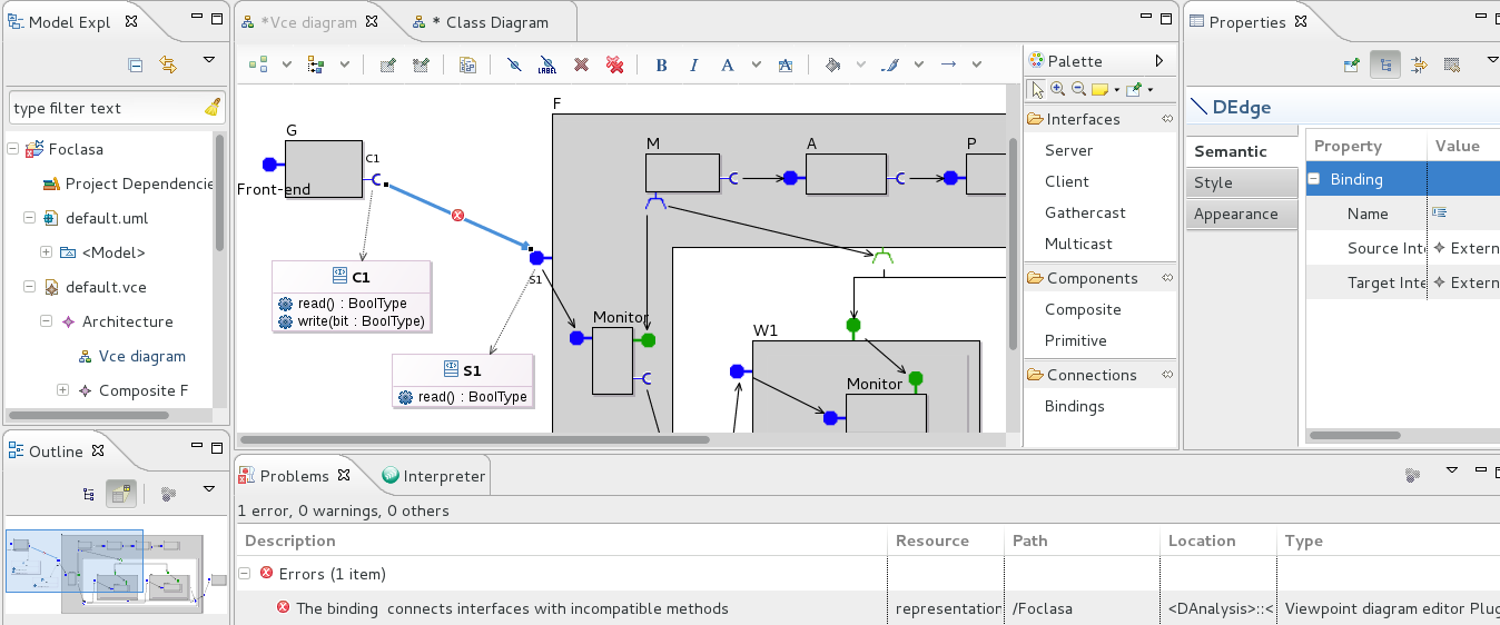
VCE v.3 is an Eclipse-based platform built using ObeoDesigner222http://www.obeodesigner.com/, EMF333http://www.eclipse.org/modeling/emf/ http://www.eclipse.org/modeling/gmf/ and GMF††footnotemark: . Figure 4 is a screen-shot of GCM Components diagram editor. It has a standard interface of an Eclipse-based application.
The static semantics constraints, defined in the previous sections are
encoded in VCE v.3 in order to validate component assemblies. The Acceleo language444http://www.eclipse.org/acceleo/ is used for the definition of such rules. An example of a rule defining the naming constraint for the components is given below:
[not self.siblings(Component)->collect(name)->includes(self.name)/]
This rule will be applied to each component. Here, self is the component on which the constraint is validated; let us denote it . The function siblings(Component) returns the set of all the components in the same container as . The function collect(name) extracts the names of all such components. Finally, includes(self.name) checks if there is any component with the same name as and returns true if it finds one.
VCE v.3 editor reports about the constraint violations. The elements of the architecture which are not correct are marked with red signs. The description of an error is given in a standard Eclipse Problem panel. Figure 4 illustrates an example of the architecture validation result; the architecture contains only one error: there is a binding between two interfaces with incompatible types (C1 and S1).
To conclude, based on the formal definitions given in this paper, we implemented an environment for the specification of the component-based applications involving group communications and with strong separation of functional and non-functional concerns. The validation of designed models ensures the correctness of the components assemblies. From this specification VerCors environment allows the verification of the behavioural properties of the system, and the generation of executable code that is safe by construction and can be run using the GCM/ProActive library.
6 Conclusion and Future Work
This article presented the formalization of rich component models with strong separation of functional and non-functional concerns, including the definition of interceptors. It also presented a tool implementing the formalized model. The main contributions of the article are:
-
•
the formal definition of GCM components including non-functional aspect and interceptors;
-
•
the formal definition of well-formness predicates including special rules for non-functional aspects, binding compatibility, and interceptors; special care has been put on the separation of concerns: the notion of control level was introduced and formally defined for the interfaces and components;
-
•
implementation of a tool for GCM-based systems architecture graphical modeling and their static semantics validation.
-
•
the identification of basic and crucial properties of the component assemblies which are guaranteed by our rules, and by the VCE platform. In particular, when a GCM application specification has been checked valid in VCE, the generated ADL file is guaranteed correct by construction, and the corresponding components will be built and deployed correctly (with no execution error) by the middleware component factory.
One of the key challenges addressed by this paper is the clear representation of interceptors chains and especially the formalization of predicates which recognize them among the other components inside a membrane.
Our approach is general enough to be extensible in order to take into account many-to-many communications or other component models.
However, the VerCors platform is not completely implemented yet. We are now working on the representation and validation of GCM-based systems behavior using UML State Machines for the definition of primitive components behavior in VCE v.3. This functionality is already partially specified and implemented. The state-machine and architecture models will be used to generate a finite semantic representation, suitable as the input to verification tools. The structural wellformess rules from this paper will have to be complemented by others, ensuring the coherency between the structural and behavioural models.
References
- [1]
- [2] OASIS Committee Draft 5 (2010): SCA Assembly Specification Version 1.1. http://oasis-open.org.
- [3] Rabéa Ameur-Boulifa, Ludovic Henrio, Eric Madelaine & Alexandra Savu (2012): Behavioural Semantics for Asynchronous Components. Rapport de recherche RR-8167, INRIA.
- [4] A. Basu, B. Bensalem, M. Bozga, J. Combaz, M. Jaber, T.H. Nguyen & J. Sifakis (2011): Rigorous Component-Based System Design Using the BIP Framework. IEEE Softw. 28(3), pp. 41–48, 10.1109/MS.2011.27.
- [5] F. Baude, D. Caromel, C. Dalmasso, M. Danelutto, V. Getov, L. Henrio & C. Pérez (2009): GCM: A Grid Extension to Fractal for Autonomous Distributed Components. Annals of Telecommunications 64(1), pp. 5–24, 10.1007/s12243-008-0068-8.
- [6] Françoise Baude, Ludovic Henrio & Cristian Ruz (2014): Programming distributed and adaptable autonomous components-the GCM/ProActive framework. Software: Practice and Experience, 10.1002/spe.2270.
- [7] S. Bensalem, M. Bozga, T.-H. Nguyen & J. Sifakis (2010): Compositional verification for component-based systems and application. IET Software 4(3), 10.1007/978-3-540-88387-6_7.
- [8] E. Bruneton, T. Coupaye, M. Leclercq, V. Quéma & J.-B. Stefani (2006): The Fractal Component Model and Its Support in Java. Software Practice and Experience, special issue on Experiences with Auto-adaptive and Reconfigurable Systems 36(11-12), 10.1002/spe.767.
- [9] Buisson, J. and André, F. and Pazat, J.L. (2005): A framework for dynamic adaptation of parallel components. In: Parallel Computing: Current & Future Issues of High-End Computing International Conference ParCo, NIC Series 33, Malaga Spain, p. 65.
- [10] T. Bureš, P. Hnetynka & F. Plasil (2006): SOFA 2.0: Balancing Advanced Features in a Hierarchical Component Model. In: Proceedings of SERA 2006, IEEE CS, pp. 40–48, 10.1109/SERA.2006.62.
- [11] H. Garavel, F. Lang, R. Mateescu & W. Serve (2011): CADP 2010: A Toolbox for the Construction and Analysis of Distributed Processes. In: TACAS’11, LNCS 6605, Springer, Heidelberg, Saarbrücken, Germany, 10.1007/978-3-642-19835-9_33.
- [12] Nuno Gaspar, Ludovic Henrio & Eric Madelaine (2013): Bringing Coq Into the World of GCM Distributed Applications. In: International Symposium on High-level Parallel Programming and Applications&, HLPP, Paris, France, 10.1007/s10766-013-0264-7. Available at http://hal.inria.fr/hal-00880533.
- [13] Ludovic Henrio, Florian Kammüller & Muhammad Uzair Khan (2010): A Framework for Reasoning on Component Composition. In: FMCO 2009, Lecture Notes in Computer Science, Springer, 10.1007/978-3-642-17071-3_1.
- [14] Petr Hnětynka & František Plášil (2006): Dynamic reconfiguration and access to services in hierarchical component models. In: Proceedings of the 9th international conference on Component-Based Software Engineering, CBSE’06, Springer-Verlag, pp. 352–359, 10.1007/11783565_27.
- [15] Philippe Merle & Jean-Bernard Stefani (2008): A formal specification of the Fractal component model in Alloy. Research Report RR-6721, INRIA. Available at http://hal.inria.fr/inria-00338987/en/.
- [16] Paul Naoumenko (2010): Designing Non-functional Aspects With Components. Ph.D. thesis, University of Nice-Sophia Antipolis.
- [17] Lionel Seinturier, Nicolas Pessemier, Laurence Duchien & Thierry Coupaye (2006): A Component Model Engineered with Components and Aspects. In: Proceedings of the 9th International SIGSOFT Symposium on Component-Based Software Engineering, 10.1007/11783565_10.