eurm10 \checkfontmsam10 \pagerange?
Radiation reaction induced non-monotonic features in runaway electron distributions
Abstract
Runaway electrons, which are generated in a plasma where the induced electric field exceeds a certain critical value, can reach very high energies in the range. For such energetic electrons, radiative losses will contribute significantly to the momentum space dynamics. Under certain conditions, due to radiative momentum losses, a non-monotonic feature – a “bump” – can form in the runaway electron tail, creating a potential for bump-on-tail-type instabilities to arise. Here we study the conditions for the existence of the bump. We derive an analytical threshold condition for bump appearance and give an approximate expression for the minimum energy at which the bump can appear. Numerical calculations are performed to support the analytical derivations.
?
1 Introduction
In a plasma, the drag force from Coulomb collisions acting on fast electrons decreases with the electron velocity. Thus, if the electric field exceeds a threshold value , electrons with sufficient velocity will be indefinitely accelerated and are called runaway electrons. The critical field is defined as
| (1) |
where is the electron density, is the electron rest mass, is the speed of light, is the elementary charge, and is the Coulomb logarithm.
Runaway electrons are generated in the presence of an induced electric field parallel to the magnetic field. In a tokamak, the condition can be met during the plasma start-up, during the flat-top phase of Ohmic plasmas if the density is sufficiently low, or in plasma disruptions. Especially during disruption events, a beam of runaways carrying a current of several MA and an energy of several , may form. Such a runaway beam would pose a serious threat to the integrity of the first wall in reactor-size fusion devices. Any mechanism that could possibly limit the formation of a considerable runaway beam would be of importance.
While the role of radiative momentum losses due to synchrotron emission has been studied previously in (Andersson et al., 2001), the possibility of a non-monotonic feature in the energy distribution of runaways – which we will henceforth refer to as a “bump” – was not considered. The formulation of the problem in (Andersson et al., 2001) does not ensure particle conservation in the presence of radiation reaction and neglects certain terms needed to describe the bump (Hazeltine & Mahajan, 2004; Stahl et al., 2015). The possibility of bump formation, however, immediately raises the question of whether the non-monotonic behavior of the distribution could lead to kinetic instabilities, causing a redistribution of the runaway particles, favorable for mitigating the potential threat to the machine. A thorough investigation of conditions favoring bump formation is thus needed.
In the present paper, we use analytical calculations to investigate the runaway electron distribution under the combined influence of Coulomb collisions, electric field acceleration, and radiative momentum losses. We show the existence of a bump and derive both a threshold condition for the appearance of the bump and an approximate expression for its location in parallel momentum space. The accuracy of the analytical estimates are then tested against numerical simulations carried out using CODE (Landreman et al., 2014; Stahl et al., 2015).
The paper is organized as follows. In Sec. 2, we start by describing the particle phase-space kinetic equation. We also discuss the transformation of the kinetic equation into the guiding-center phase-space and give the corresponding expression in the case of a uniform plasma. Analytical calculation of the condition for bump-on-tail appearance, based on the guiding-center dynamics, are presented in Sec. 3. A comparison of the derived conditions to numerical results is presented in Sec. 4, before we conclude in Sec. 5.
2 Kinetic equation
The kinetic equation describing the dynamics of charged particles in a plasma is
| (2) |
where is the collision operator for collisions between particle species and , are the phase-space coordinates, and the equations of motion. In the Fokker-Planck limit, the Coulomb collision operator is given by
| (3) |
where is the friction vector and the diffusion tensor (see Appendix A for details). In this paper, we do not consider contributions from large-angle collisions.
The equations of motion for a particle with charge and mass combine the Hamiltonian motion from the electric and magnetic fields and , and a force that accounts for non-Hamiltonian dynamics
| (4) | ||||
| (5) |
Here is the particle momentum, and is the relativistic factor. In the case considered here, the non-Hamiltonian force is the radiation reaction (RR) force which was first described by Lorentz (1892) in the case of a classical non-relativistic point charge, and was later generalized to relativistic energies by Abraham (1905) and Dirac (1938). As such, the Lorentz-Abraham-Dirac (LAD) force is (Pauli, 1958)
| (6) |
The LAD-force does however contain third order time derivatives of the particle position, which allows for the existence of pathological solutions. For instance, the particle velocity may grow exponentially in the absence of external forces (, ), see e.g. (Rohrlich, 2007). These issues have generated discussion regarding which expression to use for the RR-force. Landau & Lifshitz (1975) suggested a perturbative approach in which the velocity derivatives in Eq. (6) are expressed in terms of the external force only (here the Lorentz force). Ford & O’Connell (1993) argue that this approach is in fact the correct one. In the paper by Spohn (2000), it is shown that the non-physical solutions can be avoided if the LAD-force is limited on a so-called critical surface, and that the resulting expressions will be equivalent to those of the perturbative approach. We have thus chosen to adopt the perturbative approach. Furthermore, we neglect the electric field in the expressions for and in the RR-force. This is justified since the motion of the particle is dominated by the magnetic field in the strongly magnetized plasmas considered here. An excellent discussion about the RR-force can be found in a recent review paper by Di Piazza et al. (2012).
2.1 Guiding-center transformation
Because of the –term, the particle phase-space kinetic equation in a magnetized plasma includes the rapid gyromotion time-scale which is often not interesting and is expensive to resolve computationally. It can, however, be eliminated using guiding-center Lie-transform perturbation methods. The transformation of the Hamiltonian equations of motion is one of the classical results in modern plasma physics (see Littlejohn, 1983; Cary & Brizard, 2009), and the Fokker-Planck collision operator has been considered in (Brizard, 2004; Decker et al., 2010; Hirvijoki et al., 2013). The final step necessary to formulate our problem, the transformation of the RR-force, was given recently in (Hirvijoki et al., 2015).
After the transformation, the guiding-center kinetic equation for a gyro-angle averaged distribution function , including Hamiltonian motion in electromagnetic fields, the RR-force, and Coulomb collisions in the Fokker-Planck limit, is given by
| (7) |
where form the 5D guiding-center phase-space, is the guiding-center phase-space Jacobian, are the Hamiltonian guiding-center equations of motion, and is the contribution from the RR-force to the guiding-center motion. Similarly to the particle phase-space operator in Eq. (3), we can write the guiding-center Fokker-Planck collision operator in phase-space divergence form
| (8) |
where and are the guiding-center Coulomb friction and diffusion coefficients.
2.2 Equations of motion
We solve Eq. (7) in a uniform plasma, using 2D guiding-center velocity space coordinates , where is the absolute value of the guiding-center momentum, is the pitch-angle-cosine ( is the guiding-center momentum parallel to the magnetic field) and the guiding-center Jacobian is given by . In this case, the guiding-center equations of motion take the simple forms
| (9) | ||||
| (10) |
where is the electric field parallel to the magnetic field. The components of the guiding-center RR-force in the limit corresponding to pure synchrotron emission are (Hirvijoki et al., 2015)
| (11) | ||||
| (12) |
where the radiation reaction time-scale is defined by
| (13) |
with the classical electron radius and the gyro-frequency.
2.3 Collision operator
The particle phase-space friction and diffusion coefficients, and , are expressed in terms of the five relativistic Braams-Karney potential functions, which are weighted integrals of the background distribution functions ; (see Braams & Karney, 1989) and Appendix A for details. If the particle species and coincide, the self-collisions result in a nonlinear collision operator. In the present study, the particle phase-space collision operator is transformed into the guiding-center phase-space and linearized around a Maxwellian. The integral terms of the linearized collision operator are neglected and only the test particle contribution is considered. This choice, with some further simplifications, allows analytical solution of Eq. (7), which will be discussed in Sec. 3.
The guiding-center friction and diffusion coefficients and that appear in the guiding-center Fokker-Planck operator in Eq. (8) are gyro-averaged projections of their guiding-center push-forwarded particle phase-space counterparts. For a detailed definition of the guiding-center friction and diffusion coefficients, we refer to (Brizard, 2004; Decker et al., 2010; Hirvijoki et al., 2013). The general expressions are non-trivial but, in the limit of a uniform plasma, the test-particle operator assuming isotropic background particle distributions becomes diagonal with reasonably simple non-zero components
| (14) | ||||
| (15) | ||||
| (16) |
The coefficients , , and , where the sub-indices and stand for “longitudinal” and “transverse” with respect to the guiding-center momentum vector, are expressed in terms of the five Braams-Karney potentials with and according to
| (17) | ||||
| (18) | ||||
| (19) |
Our guiding-center Fokker-Planck operator thus becomes
| (20) |
where the first term with momentum derivatives is responsible for the slowing down of fast particles and momentum diffusion, while the second term describes scattering in pitch-angle.
2.4 Final expression
For the rest of the paper, to streamline notation, we shall suppress the brackets that denote the gyro-averaging and the sub-index from the expression for the parallel electric field. Also, we will drop the particle species indices as we sum over all the background species in the collision operator. Thus we will have , , and , and our kinetic equation in the continuity form becomes
| (21) |
In the following, we analyze this equation in detail. We describe the formation of a bump-on-tail in the electron distribution function both analytically and numerically. We also study the threshold conditions for the bump formation and the minimum energy of the bump location.
3 Characteristics of a bump-on-tail feature
The RR-force in a straight magnetic field system increases with the square of the perpendicular momentum, . As a consequence, the extent of the distribution function will, qualitatively, be limited in to a region where the parallel component of the total force acting on an electron is positive. Electrons with higher perpendicular momenta are decelerated since the radiation reaction force overcomes the acceleration due to the parallel electric field. Compared to the case without RR-force, where the distribution function is continuously expanding in for increasing values of the parallel momentum , the limited extent of the distribution in when the RR-force is included leads to qualitatively different dynamics.
The width of the distribution in is approximately constant, which means that pitch angle scattering is increasingly more effective at higher in moving the electrons to the region of phase space where they are decelerated. A consequence of this is that a true steady state solution of the kinetic equation exists and the distribution function decays exponentially in the far tail, something which was also observed in previous works, such as (Andersson et al., 2001). Another new feature is the possibility of non-monotonic behavior in the tail of the steady state distribution function. Note that this feature cannot be correctly described if the RR-force is not implemented in the phase-space divergence form that conserves the phase-space density. Therefore it is overlooked by some earlier studies. To understand the properties of the bump, and its formation, we will start the following analysis by assuming that a bump exists in the runaway tail, and make assumptions regarding its properties. These assumptions will be justified a posteriori when our results are compared to numerical results in Sec. 4.
Considering a possible bump-on-tail scenario, we study Eq. (21) in a region where the electrons have high velocities compared to the electron and ion thermal speeds . Then the slowing-down force is dominated by electron-electron collisions and it overshadows momentum diffusion. For pitch-angle-scattering, collisions with both ions and the electron bulk are important.
In the limit where the bulk populations are non-relativistic Maxwellians, we have for the friction coefficient at high speeds
| (22) |
and similarly for the transverse diffusion coefficient
| (23) |
where is the critical electric field (Eq. 1), is the effective ion charge, and . These estimates coincide with the expressions in (Andersson et al., 2001). We define the normalized momentum , time , radiation reaction time-scale , and electric field , and transform the kinetic equation into a dimensionless form for further analysis
| (24) |
As the electric field affects only the parallel acceleration we expect the system to be strongly biased about . The phase-space volume element in –coordinates (), however, scales nonlinearly close to . A better choice for further studies close to the region is to use coordinates which have a Jacobian that stays constant with respect to . The new coordinates relate to according to
| (25) | ||||
| (26) |
and our kinetic equation expressed with becomes
| (27) |
Instead of attempting to solve Eq. (27), in the following we will concentrate on the dynamics at , which will be sufficient to prove the existence of a bump and to estimate its location in the electron tail.
We assume the distribution to be a smooth function of , which allows us to create a power series expansion around :
| (28) |
Because the electric field is acting only in the parallel direction is ”even” in , i.e., we can formally state that although our phase-space does not extend to . Thus, all the odd -derivatives at must vanish, and we find
| (29) |
With the help of the expansion, we may accurately calculate the limit
| (30) |
and write the limit of the kinetic equation as
| (31) | ||||
Assuming that a steady state solution exists, the possible extrema are characterized by the condition
| (32) |
We thus find an algebraic equation that defines the locations of these extrema
| (33) |
3.1 Threshold condition for the appearance of the bump
Considering a steady-state solution to Eq. (31), in a situation where the bump is on the verge of appearing, a single inflection point exists in the distribution function instead of local maxima or minima. In this section we derive a threshold condition describing the appearance of an inflection point, by requiring the first and second -derivatives of the distribution to vanish simultaneously.
Before we start the analysis, we note that the steady state distribution function represented by Eq. (12) of (Andersson et al., 2001) is separable in and , and it is of the form , where . To find this result they neglect corrections compared to terms in the kinetic equation, which is appropriate in the very far tail [ corresponds to in the notation of (Andersson et al., 2001)]. Therefore, the quantity
| (34) |
should approach in the limit. Thus it is useful to define , so that and as . Numerical calculations tell us that for the regions of interest in the runaway tail, and it is often slowly varying function of . That is, the characteristic width of the distribution function in the direction, , decreases with increasing , and slowly asymptotes to a constant value. For now, we may simply use as a working hypothesis to be verified through numerical calculations later.
We start with the Eq. (33) satisfied at extrema or inflection of the distribution function and rewrite it as
| (35) |
where with . It is useful to form
| (36) |
where prime denotes a derivative with respect to , and we neglected a term, , assuming to be sufficiently slowly varying function of . From Eq. (36) we see that as , while . It can also be shown that only has one root for positive values of , which then has to correspond to a single maximum of .
If the distribution has an inflection point, both and should vanish there. Assuming the slowly varying to be a constant, the system of equations (35) and (36) can be solved for and to find
| (37) | ||||
and
| (38) |
where the subscript refers to values of quantities at the threshold of the bump appearance. By inspecting the expressions (37) and (38) we find that both of them increase with monotonically; between and , and between and . This means that an inflection point is always located below . Note, that we assume the inflection point to be sufficiently far from the bulk, and that is small; violation of these assumptions may move above unity. However, since this problem cannot be addressed until the more complete Eq. (21) is solved, we assume that the conditions above are fulfilled in order to proceed analytically. Since , we can make use of the expansion
| (39) |
By neglecting terms (which is reasonably good even when approaches unity), Eq. (35) becomes quadratic in :
| (40) |
At the inflection point , Eq. (40) must have a single root, which requires the discriminant to vanish. This determines the threshold value of
| (41) |
which is positive. This can be substituted back into Eq. (40) to find
| (42) |
Combining with Eq. (41) to solve for a positive that corresponds to , yields as a function of at the threshold for bump formation
| (43) |
where is treated as a parameter. When is increased above , becomes negative, and no bump appears. Reducing below unity increases the threshold value of . Thus Eq. (43) with represents an absolute lower threshold in for a monotonic behavior of the steady state distribution function. Furthermore, even at the threshold is limited to the region , thus a bump should always appear when .
We have considered , in which case can have zero (no bump), one (threshold), or two (bump exists) positive real roots. When there is only a single positive root of . Since the distribution function cannot have positive slope in the high limit this root should also correspond to a bump. That, however, requires the existence of a minimum in the distribution function along the positive axis, which must then appear outside the domain of validity of Eq. (33). In fact, this minimum will appear close to the bulk part of the electron distribution, where neglected corrections to the collision operator become important.
We can conclude that for , there should always be a bump in the steady state distribution function as long as there is a finite magnetic field. This, perhaps somewhat counter-intuitive, result needs some clarification to accommodate the well known limit. When no loss mechanisms are considered (in this case when ), the electron distribution has no steady state solution, and the runaway tail at should converge to a decay. When is small, the bump location moves to high values in , as will be shown in the next section. The runaway tail always builds up starting from the bulk and, for a tiny , the process may take such a long time that the distribution never becomes non-monotonic in practice. In this scenario the steady state distribution and the bump have no relevance. Also, other loss mechanisms may limit the distribution function to momenta below in realistic cases.
3.2 An estimate for the bump location in the far-tail
In order to proceed and estimate the location of the bump and the shape of the distribution function, we look for a steady-state solution in a region where the guiding-center parallel momentum is large. Using the expansion
| (44) |
Eq. (31) gives
| (45) |
We neglect the -term, which is valid if is not very small, and assume that the width of the distribution function in the -direction, and thus , stays approximately constant close to the bump. This essentially means that we are looking for a separable solution of the form . We obtain an ordinary differential equation
| (46) |
which is solved by
| (47) |
and the location of the bump-on-tail is given by
| (48) |
If we again assume that does not exceed unity, recalling , we find a lower bound for the parallel momentum at the bump
| (49) |
We see that for small values of , the bump would appear at high parallel momenta. By setting to some upper limit of physical interest, , Eq. (49) may be used to find an estimate for a lower “practical limit” in for the appearance of the bump. Namely, if is smaller than
| (50) |
for , then a bump would only appear at some large parallel momentum above , which is then deemed physically irrelevant. Note that if the bump is in the far tail, can be significantly less than unity, as will be shown in the next section, using numerical simulations. Letting increases the practical limit in . Another implication of Eq. (50) is that for a normalized electric field higher than , the bump always appears above for any value of .
4 Comparison to numerical results
The numerical results shown in this section were performed with the continuum simulation tool, CODE, used in its time-independent mode. CODE solves the two dimensional momentum space kinetic equation in a homogeneous plasma, using a linearized Fokker-Planck operator valid for arbitrary electron energies. For a detailed description of the tool, see (Landreman et al., 2014).
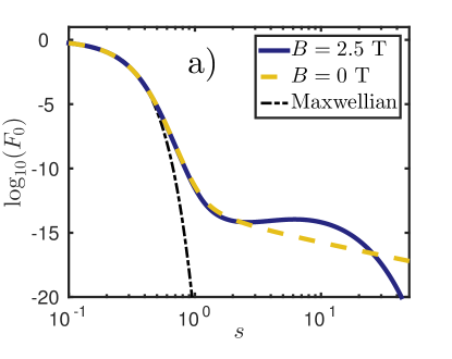
First, we provide a typical example of a non-monotonic runaway distribution function in the presence of radiation reaction. Figure 1a) shows the momentum dependence of the pitch angle averaged runaway electron distribution with () and without () radiation reaction force, plotted with solid and dashed curves respectively. Technically, the pitch-angle-averaged distribution is the lowest mode in a Legendre polynomial expansion of in , normalized so that is unity at its maximum. The simulations were performed with the parameters , , , and . Note that the distribution function without radiation reaction represents a quasi-steady state. The lack of loss mechanisms leads to a slow but steady depletion of the bulk electron population, as more and more electrons run away and leave the computational domain. This outflow must be balanced by an artificial source of thermal (Maxwellian) electrons to maintain the quasi-steady state. In the presence of radiation reaction, the distribution is a true steady state. When the radiation reaction is included, the non-monotonic feature is present when the distribution is averaged over pitch angles in the present example. However, we note that for less pronounced bumps, the pitch-angle-averaged distribution can have a monotonic tail, or it may exhibit a bump at some which are appreciably lower than those where the bump is observed in the full 2D-distribution. This may have an impact on the possibility of bump-on-tail type instabilities to arise.
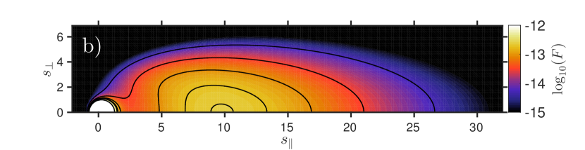
Figure 1b) shows a contour plot in – momentum space of the distribution function corresponding to the solid curve in Fig. 1a). Although this example is representative of a typical runaway electron distribution, the location and the height of the bump, and the width of the distribution in can vary significantly depending on the plasma parameters. The relation between the location and the local “width” [] of the distribution given by Eq. (48) is accurate as long as the location of the bump is not close to unity, i.e. sufficiently far from the no-bump threshold (43). This justifies the approximations applied to the collision operator in our analysis. In particular, energy diffusion can be neglected since no sharp features of the distribution function in are present, as seen in Figure 1b).
In order to investigate the validity of our analytical calculations, we have performed a numerical analysis of the appearance of the bump by scanning the parameter space with CODE. The electron temperature and density where held constant at the values and , respectively, while the magnetic field, the induced electric field and the effective ion charge were varied over the ranges , and . The numerical calculations used momentum grid points, Legendre modes for the decomposition in , and a highest resolved momentum of , provided well converged solutions.
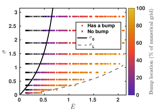
The results of the scan are presented in Fig. 2, where circles and crosses correspond to distributions with and without a bump, respectively. The color coding of the circles reflects the location of the bump, with in the color bar corresponding to . Simulations with a bump appearing above () are excluded from the figure, since those results may be affected by the bump being too close to the highest resolved momentum. As expected from Eq. (49), increasing or decreasing moves the bump towards larger momenta.
A reasonably good agreement is found between the numerical calculations and the analytical threshold for the bump to exist. The solid curve shows this threshold, Eq. (43), for . Above the “no bump” solutions obey the analytical threshold and fall to the left of the threshold curve. There are some solutions with bump in this region as well, however this is not surprising, since at the bump is allowed to be less than unity, in which case the threshold moves towards lower values of . The threshold begins to fail for lower values of , showing that the approximation used in Eq. (36) breaks down. Nevertheless, the qualitative behavior of the threshold is still captured by Eq. (43). The lower right corner of the plot (high and small ) is not populated, since some simulations where the bump would have appeared at too high were excluded. With , a value as low as is needed in order for the limit given by Eq. (50) (dashed line) to correspond well to the boundary of the region of excluded points. Thus, can be significantly lower than unity at a bump with large momentum.
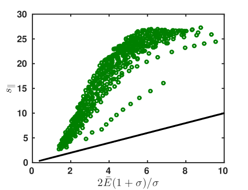
From the parameter scan used to generate Fig. 2, the simulations exhibiting bumps were compared to the theoretical lower bound for the location of the bump (Eq. 49). As shown in Fig. 3, we find that, indeed, the parallel momenta at the bumps (shown with green circles) are all higher than the lower bound (solid line). In fact, most of the values are well above this limit. This merely confirms our finding that at the bump is typically less than unity, especially for parameters sufficiently exceeding the no-bump threshold.
5 Conclusions
We have analyzed the runaway electron distribution function, accounting for the radiation reaction force, and have shown that the steady state runaway distribution can become non-monotonic. Furthermore, a threshold condition for the appearance of the bump, as well as a lower limit to its location in momentum space, were derived. While slowing down and pitch-angle scattering due to Coulomb collisions are taken into account in our analysis, we do not consider the effect of large angle collisions, and we restrict the study to a straight magnetic field geometry. Our analytical results show good agreement with numerical simulations obtained using the CODE solver.
We find that for a normalized electric field larger than unity, , the steady state electron distribution always exhibits a bump, independently of the value of the parameter quantifying the strength of the radiation reaction, as long as the magnetic field is non-vanishing (). For a smaller electric field, the appearance of the bump is well correlated with the threshold given by Eq. (43). Although above this threshold there must always be a bump in the steady state distribution function, it may not have a practical relevance in some cases. When is small and/or is large, the bump would be located at very large parallel momentum, but the forefront of the electron distribution can require a long time to reach that far. This motivates the introduction of another “practical” threshold condition, Eq. (50). If is lower than this threshold, the bump will appear at a momentum above some specified limit, , and can then be considered unimportant. In particular, above a normalized electric field of , this criterion is satisfied for any .
Nevertheless, when the radiation reaction is strong enough and/or the parallel electric field is not too high, there is a possibility for a bump to form in the runaway tail. This non-monotonic feature presents a potential source for bump-on-tail instabilities, which can play a role in limiting the formation of large runaway beams.
The authors are grateful to M. Landreman and P. Helander for fruitful discussions. IP was supported by the International Postdoc grant of Vetenskapsrådet.
Appendix A The relativistic collision operator
The relativistic particle phase-space Beliaev-Budker Collision operator in the Landau form is defined as
| (51) |
where , , , and the collision kernel is given by
| (52) |
with the coefficients
| (53) | ||||
| (54) | ||||
| (55) | ||||
| (56) |
Braams & Karney (1989) found a corresponding differential form for the collision operator
| (57) |
where is the friction vector and the diffusion tensor that are defined with differential operations on Braams–Karney potentials according to
| (58) | ||||
| (59) |
The differential operators and are defined as
| (60) | ||||
| (61) |
and the potential functions are given by the integrals
| (62) | ||||
| (63) | ||||
| (64) | ||||
| (65) | ||||
| (66) |
Furthermore, the potential functions satisfy differential relations
| (67) | ||||
| (68) | ||||
| (69) | ||||
| (70) | ||||
| (71) |
where the operator is defined
| (72) |
In the case of isotropic background distributions , the potentials become functions of only, and the friction vector and diffusion tensor can be simplified into
| (73) | ||||
| (74) |
The guiding-center transformation of the Fokker-Planck operator presented in (Brizard, 2004) gave explicit expressions for the guiding-center friction and diffusion coefficients, and , in the case of isotropic background distributions and a non-relativistic collision kernel. Generalization of that work to relativistic collision kernel is straight-forward in the case of isotropic field-particle distributions because the forms of the particle phase-space friction and diffusion coefficients do not change. Only the expressions for , , and are different but that will not affect the guiding-center transformation, as they are functions only of the guiding-center kinetic momentum.
References
- Abraham (1905) Abraham, M. 1905 Theorie der Elektrizität, Vol II: Elektromagnetische Theorie der Strahlung. Teubner Leipzig.
- Andersson et al. (2001) Andersson, F., Helander, P. & Eriksson, L.-G. 2001 Damping of relativistic electron beams by synchrotron radiation. Physics of Plasmas 8 (12), 5221–5229.
- Braams & Karney (1989) Braams, Bastiaan J. & Karney, Charles F. F. 1989 Conductivity of a relativistic plasma. Physics of Fluids B 1 (7), 1355–1368.
- Brizard (2004) Brizard, A. J. 2004 A guiding-center Fokker–Planck collision operator for nonuniform magnetic fields. Physics of Plasmas 11 (9), 4429–4438.
- Cary & Brizard (2009) Cary, John R. & Brizard, Alain J. 2009 Hamiltonian theory of guiding-center motion. Reviews of Modern Physics 81, 693–738.
- Decker et al. (2010) Decker, J., Peysson, Y., Brizard, A. J. & Duthoit, F.-X. 2010 Orbit-averaged guiding-center Fokker-Planck operator for numerical applications. Physics of Plasmas 17 (11), 112513.
- Di Piazza et al. (2012) Di Piazza, A., Müller, C., Hatsagortsyan, K. Z. & Keitel, C. H. 2012 Extremely high-intensity laser interactions with fundamental quantum systems. Rev. Mod. Phys. 84, 1177–1228.
- Dirac (1938) Dirac, P. A. M. 1938 Classical theory of radiating electrons. Proceedings of the Royal Society of London. Series A, Mathematical and Physical Sciences 167 (929), pp. 148–169.
- Ford & O’Connell (1993) Ford, G.W & O’Connell, R.F 1993 Relativistic form of radiation reaction. Physics Letters A 174 (3), 182 – 184.
- Hazeltine & Mahajan (2004) Hazeltine, R. & Mahajan, S. 2004 Radiation reaction in fusion plasmas. Physical Review E 70, 046407.
- Hirvijoki et al. (2013) Hirvijoki, E., Brizard, A., Snicker, A. & Kurki-Suonio, T. 2013 Monte Carlo implementation of a guiding-center Fokker-Planck kinetic equation. Physics of Plasmas 20 (9), 092505.
- Hirvijoki et al. (2015) Hirvijoki, E., Decker, J., Brizard, A. & Embreus, O. 2015 Guiding-center transformation of the Abraham-Lorentz-Dirac radiation reaction force. Submitted to Journal of Plasma Physics .
- Landau & Lifshitz (1975) Landau, L. D. & Lifshitz, E. M. 1975 The Classical Theory of Fields, fourth edition edn., Course of Theoretical Physics, vol. 2. Amsterdam: Pergamon.
- Landreman et al. (2014) Landreman, Matt, Stahl, Adam & Fülöp, Tünde 2014 Numerical calculation of the runaway electron distribution function and associated synchrotron emission. Computer Physics Communications 185 (3), 847 – 855.
- Littlejohn (1983) Littlejohn, Robert G. 1983 Variational principles of guiding centre motion. Journal of Plasma Physics 29, 111–125.
- Lorentz (1892) Lorentz, H.A. 1892 La Théorie Électromagnétique de Maxwell et Son Application Aux Corps Mouvants. Archives Nederlandaises des Sciences Exactes et Naturelles 25, 363–552.
- Pauli (1958) Pauli, W. 1958 Theory of Relativity. Dover Publications.
- Rohrlich (2007) Rohrlich, F. 2007 Classical Charged Particles. World Scientific.
- Spohn (2000) Spohn, H. 2000 The critical manifold of the lorentz-dirac equation. Europhysics Letters 50 (3), 287.
- Stahl et al. (2015) Stahl, A., Hirvijoki, E., Decker, J., Embréus, O. & Fülöp, T. 2015 Effective critical electric field for runaway-electron generation. Phys. Rev. Lett. 114, 115002.