Planck 2015 results. IV. Low Frequency Instrument beams and window functions
This paper presents the characterization of the in-flight beams, the beam window functions, and the associated uncertainties for the Planck Low Frequency Instrument (LFI). The structure of the paper is similar to that presented in the 2013 release; the main differences concern the beam normalization and the delivery of the window functions to be used for polarization analysis. The in-flight assessment of the LFI main beams relies on measurements performed during observations of Jupiter. By stacking data from seven Jupiter transits, the main beam profiles are measured down to –25 dB at 30 and 44 GHz, and down to –30 dB at 70 GHz. It has been confirmed that the agreement between the simulated beams and the measured beams is better than 1% at each LFI frequency band (within the 20 dB contour from the peak, the rms values are 0.1% at 30 and 70 GHz; 0.2% at 44 GHz). Simulated polarized beams are used for the computation of the effective beam window functions. The error budget for the window functions is estimated from both main beam and sidelobe contributions, and accounts for the radiometer band shapes. The total uncertainties in the effective beam window functions are 0.7% and 1% at 30 and 44 GHz, respectively (at ); and 0.5 % at 70 GHz (at ).
Key Words.:
methods: data analysis – cosmology: cosmic microwave background – telescopes1 Introduction
This paper, one of a set associated with the 2015 release of data from the Planck111Planck (http://www.esa.int/Planck) is a project of the European Space Agency (ESA) with instruments provided by two scientific consortia funded by ESA member states and led by Principal Investigators from France and Italy, telescope reflectors provided through a collaboration between ESA and a scientific consortium led and funded by Denmark, and additional contributions from NASA (USA). mission, describes the beams and window functions of the Low Frequency Instrument (LFI). The structure of the paper is similar to that presented in Planck Collaboration IV (2014); the main differences concern the beam normalization and the delivery of the window functions to be used for polarization analysis.
We summarize here the general framework and the nomenclature adopted, which is the same as that used in Planck Collaboration IV (2014). The LFI optical layout is composed of an array of 11 corrugated feed horns, each coupled to an orthomode transducer (OMT), which splits the incoming electromagnetic wave into two orthogonal, linearly polarized components. Thus, the LFI observed the sky with 11 pairs of beams, associated with 22 pseudo-correlation radiometers. Each beam in a pair is named LFIXXM or LFIXXS for the two polarization states (“Main” Arm and “Side” Arm of the orthomode transducer, respectively). Here XX is the radiometer chain assembly number, ranging from 18 to 28. The beams from LFI18 to LFI23 are in the V–band (nominally from 63 to 77 GHz); we refer to them as 70 GHz. The beams from LFI24 to LFI26 are in the Q–band (from 39.6 to 48.4 GHz); we refer to them as 44 GHz. The beams LFI27 and LFI28 are in the Ka–band (from 27 to 33 GHz); we refer to them as 30 GHz. The fundamental definitions introduced in Planck Collaboration IV (2014), i.e., optical beams, scanning beams, and effective beams, can be found in Appendix A.
In the framework of this paper, and the Planck LFI companion papers, we considered three regions defined with respect to the beam boresight:
-
1.
the main beam, which is defined as extending to 1.9∘, 1.3∘, and 0.9∘ at 30, 44, and 70 GHz, respectively;
-
2.
the near sidelobes, which are defined as extending between the main beam angular limit and 5∘;
-
3.
the far sidelobes, which are defined as the beam response greater than 5∘ from the boresight.
The scanning beams used in the LFI pipeline (affecting calibration, effective beams, and beam window functions) are very similar to those presented in Planck Collaboration IV (2014): they are beams computed with GRASP222The GRASP software was developed by TICRA (Copenhagen, DK) for analysing general reflector antennas (http://www.ticra.it)., properly smeared to take into account the satellite motion. Simulations have been performed using the optical model described in Planck Collaboration IV (2014), which was derived from the Radio Frequency Flight Model (Tauber et al. 2010) by varying some optical parameters (e.g., the relative distance between the two mirrors and the focal plane unit, the feed horn locations and orientations) within the nominal tolerances expected from the thermoelastic model, in order to reproduce the measurements of the LFI main beams from seven Jupiter transits. This tuned optical model is able to represent all the measured LFI main beams with an accuracy of about 0.1% at 30 and 70 GHz, and 0.2% at 44 GHz333These values represent the rms value of the difference between measurements and simulations, computed within the 20 dB contour..
Unlike the case in Planck Collaboration IV (2014), a different beam normalization is introduced here to properly take into account the actual power entering the main beam (typically about 99% of the total power). This is discussed in Sect. 2.
In Sect. 3 the details of the main beam reconstruction from the Jupiter transits are presented. The comparison between the measured scanning beam and GRASP scanning beams is also shown. Section 4 presents the descriptive parameters of the effective beams, needed for the evaluation of the flux densities of the point sources from the maps. In Sect. 5 we present the beam window functions for temperature and polarization analysis. In the computation of the effective beams and their related window functions, we have significantly increased the outer radius (for 70 GHz this means a change from 2.5 FWHM to 4 FWHM) to minimize the effect of the cut-off radius. The effect of near and far sidelobes on the window functions is described in the same section. The normalization of the window function reflects the main beam efficiencies presented in Sect. 2. The main parameter that affects the polarization (EE) beam window functions was confirmed to be the beam ellipticity, which leads to a temperature-to-polarization leakage of about 15 % at multipole equal to 1000 (at 70 GHz) compared to an ideal case of a symmetrical Gaussian beam. The error budget on the window functions is presented in Sect. 6.
2 Beam normalization
In previous work (Planck Collaboration IV 2014), the main beam used in the calculation of the effective beams (and effective beam window functions) was a full-power main beam (i.e., unrealistically set to 100 % efficiency). The resulting beam window function was normalized to unity because the calibration was performed assuming a pencil beam. This assumption considers that all the power entering the feed horn comes from the beam line of sight. We know that this assumption is not realistic, since up to 1% of the solid angle of the LFI beams falls into the sidelobes, unevenly distributed and concentrated mainly in two areas, namely the main-reflector and sub-reflector spillover (see Fig. 1). The main-reflector spillover is primarily due to the rays reflected by the lower part of the sub-reflector and those diffracted by the two reflectors; it peaks at about 90∘ from the telescope line of sight, along the direction of the satellite spin axis, and it has an intensity below –50 dB from the main beam power peak. The sub-reflector spillover (whose intensity is lower than the main-reflector spillover) is generated by the rays entering the feed without any interaction with the reflectors; its shape aligns roughly with the feed, pointing at about 20∘ from the line of sight of the telescope. They are both extended structures whose shape and power change significantly across the band.

Because we accurately model the dipole signal, by convolving the sky dipole with the full beam response of each radiometer, our calibration procedure correctly converts the time-ordered data into received antenna temperature in kelvin, where that temperature represents the full-sky temperature weighted by the beam (Planck Collaboration V 2015). Our mapping procedure assumes a pencil beam (Planck Collaboration VI 2015), which in the ideal case of a circularly-symmetric beam would yield a map of the beam-convolved sky; however, a fraction of the signal from any source appears in the far sidelobes, and would be missed by integration of the map over the main beam alone. By the same token, bright resolved features in the map have temperatures fractionally lower than in the sky, due to signal lost to the sidelobes. In essence this description remains true even given the highly asymmetric sidelobes of the Planck beam: the main difference is that the far sidelobe contribution to a given pixel varies according to the orientation of the satellite at the time of observation. This is handled by explicitly subtracting a model of the Galactic straylight and treating the remaining effect as a noise term. Important to note is that the roughly 1% of the signal found in the sidelobes is missing from the vicinity of the main beam, so the main beam efficiency %; and this must be accounted for in any analysis of the maps. In particular, the window function used to correct the power spectra extracted from the maps (which is based on the main beam only) allows for this efficiency. Likewise, to calculate the flux densities of compact sources from LFI maps, we should correct for the main beam efficiency or, alternatively, deconvolve the beam from the map before calculating the flux densities (the latter approach takes into account the true beam shape, not just its angular resolution and/or solid angle). In other words, the source flux densities must be scaled up by a correction factor, as presented in Planck Collaboration II (2015). In particular, the scaling factors are 1.00808, 1.00117, and 1.00646 at 30, 44, and 70 GHz, respectively.
The efficiency values listed in Table 1 were calculated by taking into account the variation across the band of the optical response (coupling between feed horn pattern and telescope) and the radiometric response. The bandpass of each radiometer is unique, since it depends very sensitively on the manufacturing process. Therefore two beams that are optically similar (e.g., mirror-symmetric, such as 18S and 23S) have different main beam efficiencies; and two beams that might be expected to have different efficiencies (because the off-axis telescope responds differently to the two polarizations) are characterized by very similar efficiencies (for example, 22M and 22S). The impact of this imbalance in the efficiencies is not negligible for the 30 GHz window functions; it generates a bump at low compared to the previous release which treated an ideal case in which the beams were normalized to unity (see Fig. 14 in Sect. 5). At higher frequencies this impact is negligible.
Table 1 reports the main beam efficiency of each LFI beam as well as the percentage of the power entering the near and far sidelobes. We note that there is a small fraction of power in LFI sidelobes, resulting from the first-order approximation adopted in the computation carried out with the GRASP Multi-reflector Geometrical Theory of Diffraction (MrGTD) (Ticra 2012). In Planck Collaboration IV (2014) we expressed the hope that we could include in the current paper the higher order contributions, but we found that the computational cost of such an analysis, performed across the band, was prohibitive. However, we performed some tests in collaboration with HFI, comparing the straylight evaluated with sidelobes computed at the 1st and 7th orders, and found that the resulting differences are negligible, both at map level (0.2 K) and power spectrum level (lower than 10-15 K2). In other words, it does seem that the missing power is broadly distributed at a low power level and does not have a significant impact on the straylight contamination, which is clearly dominated by the main-reflector spillover.
| Beam | Total | |||
| 70 GHz | ||||
| 18S | 98.87 | 0.12 | 0.62 | 99.60 |
| 18M | 99.21 | 0.09 | 0.38 | 99.68 |
| 19S | 98.98 | 0.11 | 0.58 | 99.66 |
| 19M | 98.83 | 0.13 | 0.60 | 99.56 |
| 20S | 98.81 | 0.13 | 0.70 | 99.64 |
| 20M | 98.85 | 0.13 | 0.63 | 99.61 |
| 21S | 98.82 | 0.13 | 0.70 | 99.65 |
| 21M | 98.94 | 0.11 | 0.59 | 99.64 |
| 22S | 99.15 | 0.08 | 0.50 | 99.73 |
| 22M | 99.16 | 0.08 | 0.44 | 99.69 |
| 23S | 99.19 | 0.09 | 0.43 | 99.71 |
| 23M | 99.26 | 0.08 | 0.35 | 99.69 |
| 44 GHz | ||||
| 24S | 99.73 | 0.03 | 0.15 | 99.91 |
| 24M | 99.72 | 0.03 | 0.15 | 99.90 |
| 25S | 99.76 | 0.02 | 0.06 | 99.84 |
| 25M | 99.75 | 0.03 | 0.08 | 99.86 |
| 26S | 99.77 | 0.02 | 0.05 | 99.84 |
| 26M | 99.74 | 0.03 | 0.08 | 99.85 |
| 30 GHz | ||||
| 27S | 98.89 | 0.09 | 0.76 | 99.75 |
| 27M | 99.04 | 0.08 | 0.64 | 99.76 |
| 28S | 98.79 | 0.10 | 0.83 | 99.73 |
| 28M | 99.07 | 0.07 | 0.62 | 99.76 |
3 Scanning beams
3.1 Planet data
The LFI in-flight main beam reconstruction is based on the same method adopted in the past release (Planck Collaboration IV 2014). In Fig. 3 the LFI footprint on the sky is shown for both polarization arms. In contrast to the analogous figure reported in Planck Collaboration IV (2014), here the beams are plotted down to –30 dB at 70 GHz, and –25 dB at 30 and 44 GHz.
To assess the beam properties, we used seven Jupiter transits (Planck Collaboration II 2015). The first four transits (J1 to J4) occurred in nominal scan mode (spin shift 2 arcmin, 1 degree per day), and the last three scans (J5 to J7) in deep mode (shift of the spin axis between rings of 0.5 arcmin, 15 arcmin per day). Figure 2 shows two Jupiter scans at 70 GHz: the first one, in nominal mode; and the seventh, in deep mode. Some data from the first deep scan have been discarded and, for this reason we used only the last two deep scans at the lower frequencies (30 and 44 GHz). For the 70 GHz channel, the resulting sampling of the uv-plane is about 3.4 times better than in the earlier paper and, consequently, the signal-to-noise ratio is about 1.8 times better. At 44 and 30 GHz the improvement is slightly lower (1.3 and 1.5 times better, respectively), since data from the first deep scan could not be used due to spacecraft manoeuvrements. As a result of the deeper sampling, the error on the reconstructed beam parameters is lower with respect to the previous release, as can be seen by comparing Table 2 with table 2 of Planck Collaboration IV (2014), and the error envelope on the window functions is lower as well.

 |
 |
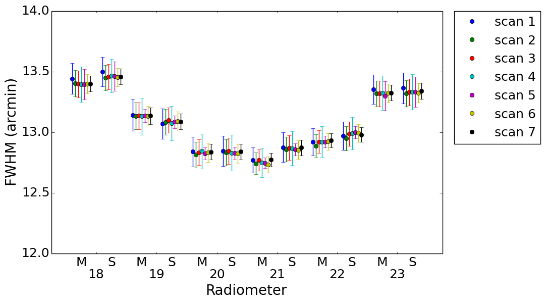
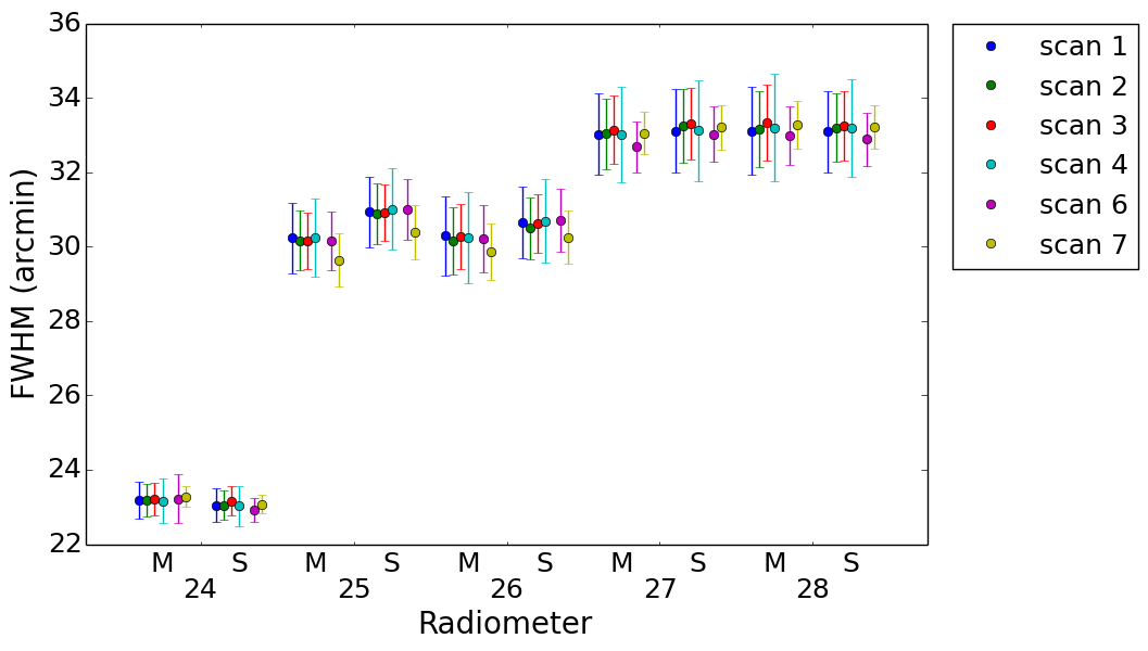
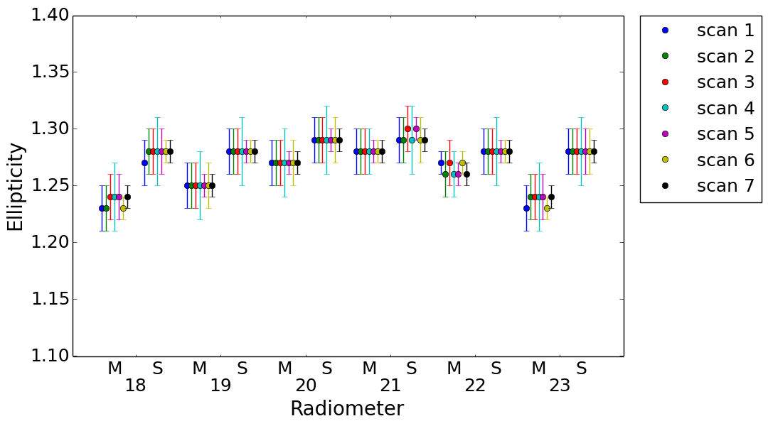
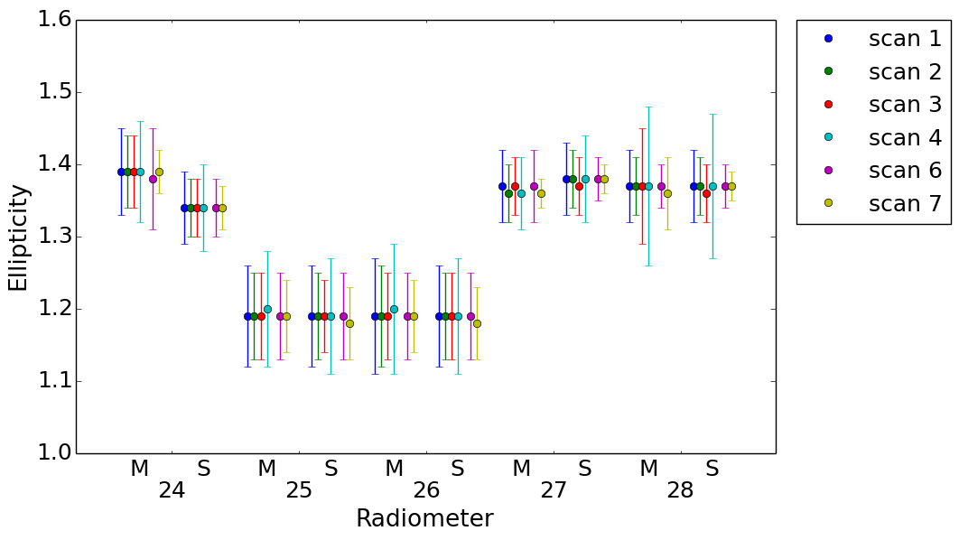
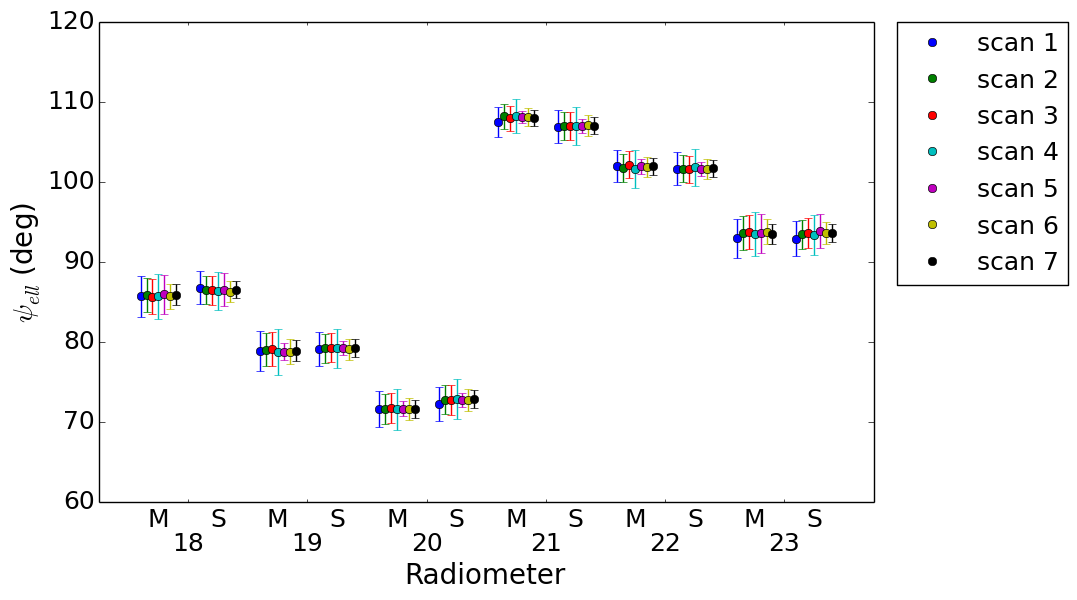
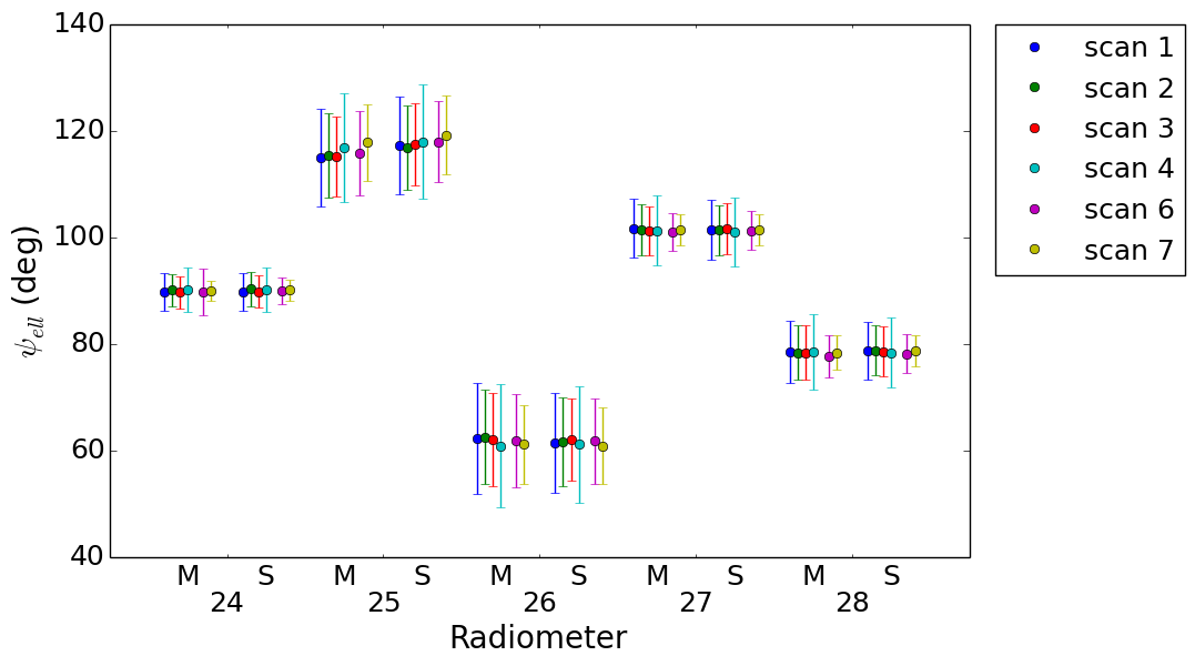
Table 2 reports the main beam descriptive parameters with the estimated uncertainties evaluated from the stacked beams obtained using all seven Jupiter transits. Figs. 4, 5, and 6 show the values of FWHM, ellipticity, and beam orientation derived from each Jupiter transit. The scatter among the values reconstructed from different transits is much smaller than that expected from the errors quoted for each transit, which conservatively includes any possible systematic effects. The main uncertainty comes from the fact that the elliptical Gaussian representation of the beam shape, adopted only in this fit, although accurate at a level of few K for characterizing the power entering the main beam and the signal convolved with sky diffuse emissions (Burigana et al. 2001), shows a small point-to-point difference with the reconstructed beam at a level of a few percentage points. If we consider only the statistical properties of the noise and sky fluctuations, as measured from the analysis of the signal variance just outside the main beam, the resulting error bars would be about ten times smaller, but in this release we adopted a conservative approach to define the uncertainties in the beam window functions. It is evident that the seven measurements give basically the same results. Thus, no time-dependent optical effects are evident in these data, which were taken from October 2009 to February 2013.
With respect to the previous main beam reconstruction using four Jupiter transits (Planck Collaboration IV 2014), there is an improvement in the uncertainties on the FWHM, ellipticity, and , respectively, by factors of about 1.8, 3.1, and 1.8 at 70 GHz; 1.5, 2.1, and 1.5 at 44 GHz; and 1.6, 1.9, and 1.6 at 30 GHz. These numbers reflect the improvement in the coverage of the uv-plane of the stacked beams: the number of samples including the three deep scans is about 3.4 times higher at 70 GHz, 1.7 at 44 GHz, and 2.2 at 30 GHz. For completeness, in Appendix B the fitted parameters are reported for each scan.
| Beam | FWHM | Ellipticity | ||
| (arcmin) | (degrees) | |||
| 70 GHz | ||||
| 18M | 13.40 0.02 | 1.235 0.004 | 85. | 74 0.41 |
| 18S | 13.46 0.02 | 1.278 0.004 | 86. | 41 0.33 |
| 19M | 13.14 0.02 | 1.249 0.003 | 78. | 82 0.35 |
| 19S | 13.09 0.02 | 1.281 0.002 | 79. | 15 0.30 |
| 20M | 12.83 0.02 | 1.270 0.003 | 71. | 59 0.32 |
| 20S | 12.83 0.02 | 1.289 0.004 | 72. | 69 0.31 |
| 21M | 12.75 0.02 | 1.280 0.003 | 107. | 99 0.27 |
| 21S | 12.86 0.02 | 1.294 0.003 | 106. | 96 0.29 |
| 22M | 12.92 0.02 | 1.264 0.003 | 101. | 87 0.30 |
| 22S | 12.99 0.02 | 1.279 0.003 | 101. | 61 0.30 |
| 23M | 13.32 0.02 | 1.235 0.004 | 93. | 53 0.40 |
| 23S | 13.33 0.02 | 1.279 0.004 | 93. | 49 0.36 |
| 44 GHz | ||||
| 24M | 23.18 0.05 | 1.388 0.005 | 89. | 82 0.33 |
| 24S | 23.03 0.04 | 1.344 0.003 | 89. | 97 0.34 |
| 25M | 30.02 0.07 | 1.191 0.005 | 115. | 95 0.75 |
| 25S | 30.79 0.07 | 1.188 0.005 | 117. | 70 0.74 |
| 26M | 30.13 0.08 | 1.191 0.006 | 61. | 89 0.84 |
| 26S | 30.52 0.08 | 1.189 0.006 | 61. | 53 0.77 |
| 30 GHz | ||||
| 27M | 32.96 0.06 | 1.364 0.005 | 101. | 20 0.34 |
| 27S | 33.16 0.07 | 1.379 0.005 | 101. | 29 0.34 |
| 28M | 33.17 0.07 | 1.366 0.006 | 78. | 17 0.36 |
| 28S | 33.12 0.07 | 1.367 0.005 | 78. | 47 0.33 |
3.2 Polarized scanning beams
The polarized scanning beams have been evaluated from optical simulations carried out by the application of physical optics and physical theory of diffraction using GRASP. As reported in Planck Collaboration IV (2014), these beams came from a dedicated optical study that has been carried out with the goal of fitting the simulated beams to the in-flight measurements. Of course, to take into account the satellite motion, the optical beams have been properly smeared. The impact of the polarization of Jupiter is negligible because it is well below the level of beam measurements (see Appendix B of Planck Collaboration IV (2014) for a detailed description and evaluation of such effect).
The Low Frequency Instrument performs polarization measurements of the cosmic microwave background (CMB) anisotropies by combining the signal received by the feed horns appropriately aligned in the focal plane (Leahy et al. 2010). All LFI feed horns are off-axis and the respective main beams, located at 3 to 5∘ from the telescope line of sight (LOS), suffer some aberration. The LFI main beams can be considered linearly polarized, to first order, but we are conscious of the impact of a non-null cross-polarization close to the main beam pointing direction. Knowledge of the polarization properties of each main beam (i.e., co- and cross-polar components) and of the spacecraft pointing direction are required to perform polarization measurements. Since we were not able to measure the cross-polar beam in flight, we have relied on simulations validated by far more accurate beam measurements than those reported earlier in Planck Collaboration IV (2014). The strength of the model adopted is twofold: (i) we have a description of the beams at levels lower than the instrumental noise; and (ii) the beam cross-polar component is fully characterized.
The GRASP main beams were computed in uv-spherical polar grids (see Appendix A for the definition of the main beam region). In each point of the uv-grid, the far field was computed in the co- and cross-polar basis according to Ludwig’s third definition (Ludwig 1973).
Although the GRASP beams are computed as the far-field angular transmission function of a highly polarized radiating element in the focal plane, the far-field pattern is in general no longer exactly linearly polarized: a spurious component, induced by the optics, is present (Sandri et al. 2010). The co-polar pattern is interpreted as the response of the linearly polarized detector to radiation from the sky that is linearly polarized in the direction defined as co-polar, and the same is true for the cross-polar pattern, where the cross-polar direction is orthogonal to the co-polar one. The Jupiter scans allow us to measure only the total field, that is, the co- and cross-polar components combined in quadrature. The total field of GRASP beams fits the Jupiter data, but these beams also have the co- and cross-polar pattern defined separately. The adopted beam reference frame, in which each main beam was computed, implies that the power peak of the co-polar component lies in the centre of the uv-grid, and a minimum in the cross-polar component appears at the same point. In particular, the major axis of the polarization ellipse is along the u-axis for the radiometer side arm and it is aligned with v- for the radiometer main arm. This means that, very close to the beam pointing direction, the main beam can be assumed to be linearly polarized; the x-axis of the main beam frame can be assumed to be the main beam polarization direction for the radiometers S; and the y-axis of the main beam frame can be assumed to be the main beam polarization direction for the radiometers M.
We have evaluated the effect of cross-polarization on the window functions, and find that it is roughly 1% at 70 GHz for equal to 1000. The GRASP beams are normalized to have an integrated solid angle of sr. The integral over the main beam region (the summed co- and cross-polar power) is representative of the main beam efficiency.
3.3 Hybrid beams
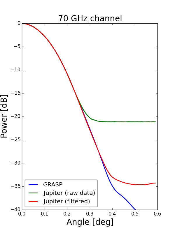
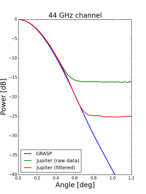
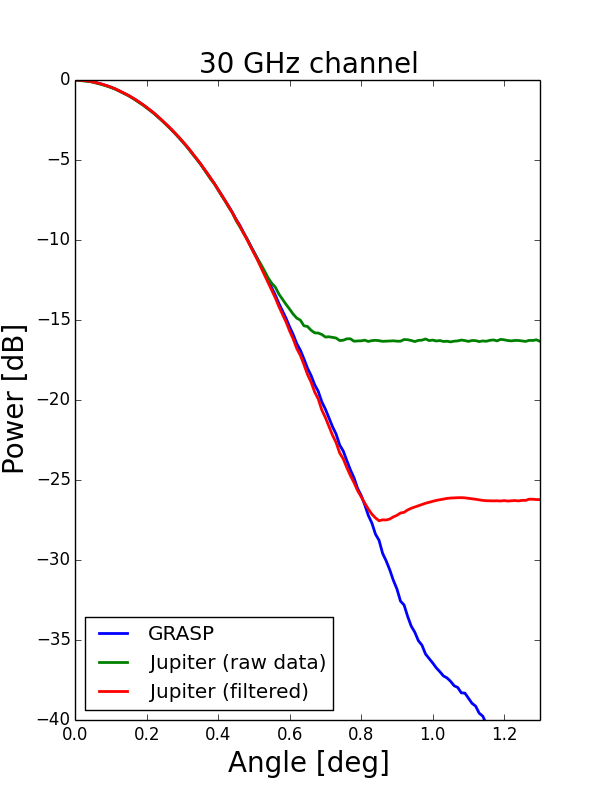
Unlike in the previous release, this time we have produced a new main beam model named the “hybrid beam”. Hybrid beams have been created using planet measurements above 20 dB below the main beam power peak and GRASP beams below this threshold (see Figs. 7 and 8). The planet data have been filtered using a maximally flat magnitude filter (Butterworth filter) to reduce the noise. The hybrid beams have been normalized according to the GRASP beams (i.e., the main beam efficiency is set to the same value). We used the hybrid beams to perform a further check on the consistency between the GRASP model and the planet data, in terms of window functions. Figure 9 shows the comparison between the symmetrized GRASP beams and the planet data. The polarized beams provide the best fit to the available measurements of the LFI main beams from Jupiter; this model represents all the LFI beams with an accuracy of about 0.1% at 30 and 70 GHz, and 0.2% at 44 GHz (rms value of the difference between measurements and simulations, computed within the 20 dB contour). Figure 10 shows for all channels the comparison between the window functions computed using GRASP beams and the window functions computed using hybrid beams.


|
4 Effective beams
The effective beam is defined in the map domain, and is obtained by averaging the scanning beams that are pointed at a given pixel of the sky map, while taking into account both the scanning strategy and the orientation of the scanning beams when they point at that pixel. The effective beams thus capture information about the difference between the true and observed images of the sky. They are, by definition, the objects whose convolution with the true CMB sky produces the observed sky map, at least in the absence of sidelobes. Similarly, the effective beam window functions capture the ratio between the true and observed angular power spectra. As in Planck Collaboration IV (2014), we compute in this paper the effective beam at each sky pixel for each LFI frequency scanning beam, and scan history using the FEBeCoP method. For a detailed account of the algebra involving the effective beams for temperature and polarization see Mitra et al. (2011).
The main beam solid angle of the effective beam, , is estimated as the integral over the full extent of the effective beam. A larger cut-off radius has been applied to the main beams: 113.6 arcmin at 30 GHz; 79 arcmin at 44 GHz; and 52 arcmin at 70 GHz. From the effective beam solid angle, we can estimate the effective full width half maximum (FWHMeff), assuming a Gaussian of equivalent solid angle. These values have been averaged across the map to obtain the band (quadruplets) averaged effective beam solid angles listed in Table LABEL:tab:stat1. The spatial variation is the 1 uncertainty associated with the band (quadruplets) averaged beams.
In Table LABEL:tab:stat2, we report the FWHM computed in a different way, by forming the averages of the FWHM evaluated evaluated from a Gaussian fit to the effective beam maps. The former is best used for flux determination, the latter for source identification.
| Band | spatial variation | spatial variation | spatial variation | FWHMeff | spatial variation | |||||||||||
|---|---|---|---|---|---|---|---|---|---|---|---|---|---|---|---|---|
| (arcmin2) | (arcmin2) | (arcmin2) | (arcmin2) | (arcmin2) | (arcmin2) | (arcmin) | (arcmin) | |||||||||
| 30 | 1190. | 06 | 0. | 69 | 1117. | 3 | 1. | 8 | 1188. | 93 | 0. | 70 | 32. | 408 | 0. | 009 |
| 44 | 832. | 00 | 34. | 00† | 758. | 0 | 32. | 0† | 832. | 00 | 35. | 00† | 27. | 100 | 0. | 570† |
| 70 | 200. | 90 | 0. | 99 | 186. | 1 | 1. | 8 | 200. | 59 | 0. | 99 | 13. | 315 | 0. | 033 |
| 18/23 | 210. | 13 | 0. | 63 | 194. | 2 | 2. | 6 | 209. | 82 | 0. | 64 | 13. | 618 | 0. | 020 |
| 19/22 | 199. | 19 | 0. | 64 | 185. | 0 | 1. | 6 | 198. | 90 | 0. | 64 | 13. | 259 | 0. | 021 |
| 20/21 | 192. | 58 | 0. | 67 | 179. | 1 | 1. | 9 | 192. | 27 | 0. | 67 | 13. | 037 | 0. | 023 |
| 25/26 | 1019. | 63 | 0. | 65 | 942. | 2 | 2. | 4 | 1019. | 05 | 0. | 64 | 29. | 998 | 0. | 009 |
-
•
† The large spatial variation associated with the 44 channel is due to the combination of beams with very different shapes and orientations, due to the different location of horn 24 with respect to horns 25 and 26 in the focal plane (Sandri et al. 2010). Indeed, the value associated with the quadruplet 25/26 (the spatial variation of the 24 is about 0.78 arcmin2) is in line with other quadruplets.
| FWHM | Ellipticity | |||||||||
|---|---|---|---|---|---|---|---|---|---|---|
| Band | mean | stdev | mean | stdev | mean | stdev | ||||
| (arcmin) | (arcmin) | (degree) | (degree) | |||||||
| 30 | 32. | 293 | 0. | 024 | 1. | 318 | 0. | 037 | 0 | 54 |
| 44 | 27. | 000 | 0. | 590 | 1. | 035 | 0. | 035 | 0 | 50 |
| 70 | 13. | 213 | 0. | 034 | 1. | 223 | 0. | 026 | 3 | 54 |
| 18/23 | 13. | 525 | 0. | 021 | 1. | 188 | 0. | 021 | 3 | 54 |
| 19/22 | 13. | 154 | 0. | 037 | 1. | 230 | 0. | 027 | 2 | 54 |
| 20/21 | 12. | 910 | 0. | 037 | 1. | 256 | 0. | 036 | 3 | 54 |
| 25/26 | 29. | 975 | 0. | 013 | 1. | 177 | 0. | 030 | –2 | 47 |
5 Beam window function
5.1 LFI window functions based on FEBeCoP
FEBeCoP beam window functions have been computed as presented in Planck Collaboration IV (2014). In the current release we deliver both and window functions defined as
| (1) |
where the ensemble average is taken over the Monte Carlo (MC) simulations of the CMB observations, is the power spectrum of the CMB-only maps simulated by FEBeCoP as described in (Mitra et al. 2011), and is the fiducial model used as input. These are shown in Fig. 10 for 30, 44, and 70 GHz frequency maps (temperature and polarization), using two different beam models (GRASP beams and hybrid beams). Figure 11 shows the difference between the current window functions and the old ones, delivered in 2013. The main difference is in the normalization, with the current window functions taking into account the power missed by the main beams, whereas the old ones were computed using full-power main beams. Naturally, the actual pointing solution is different with respect to that used in the past release (Planck Collaboration II 2015).
As done in 2013, we verified that for the Galactic mask used for power spectrum estimation (Planck Collaboration II 2015; Planck Collaboration XI 2015) the differences between full-sky and cut-sky window functions are marginal with respect to the error envelopes discussed in Sect. 6, therefore the full-sky approximation has been used.
The oscillations in the window functions, located at values of corresponding to the acoustic peaks, hint at the presence of temperature-to-polarization leakage, likely caused by the coupling of the scanning strategy with the particular shape of scanning beams. To demonstrate this, we compare the window functions of the 18/23 quadruplet computed using a circular Gaussian, an elliptical Gaussian and a more realistic GRASP scanning beam. In Fig. 12 the window function for the 18/23 quadruplet (at 70 GHz) is shown. It is noteworthy that for the circular Gaussian no oscillations are present, while the main contribution to the leakage (15 % at = 900) is due to the beam ellipticity. The actual beam shape also has an effect (see the right panel of the Fig. 12, comparison between blue and green curves), but it is minor with respect to the ellipticity effect (blue curve).
 |
 |

Regarding the beam cross-polarization, since the delivered window functions have been obtained from GRASP beams, where the cross-polarization is properly taken into account, no approximation is required. Nevertheless we evaluated the effect of the beam cross-polarization by computing the window functions, including and not including the cross-polar beam component, as described in (Jones et al. 2007). The results are presented in Fig. 13. The effect of including the cross-polar beam in the window function computation for 70 GHz is roughly 1% at = 1000. Including the cross-polar term can approximately be described by an overall smoothing effect. A Gaussian beam of about 51 arcseconds accurately describes the extra smoothing effect up to = 1000 for 70 GHz, and deviates from the real effect for large multipoles, overpredicting the amount of smoothing.
Another interesting effect on the polarized window function is related to the different main beam efficiencies, mainly at 30 GHz. This effect is shown in Fig. 14. From this figure it is evident that there is a bump at low multipoles with respect to the window function delivered in 2013. This bump is not due to the different beam shape or the different pointing solution, but rather to the fact that the beams have, reasonably, different efficiencies due to mechanical issues.
Since the beam window functions are computed using CMB-only Monte Carlo simulations, the oscillations we see in the polarization s only account for the leakage of the CMB signal itself and not for foreground-induced leakage.
 |
 |
 |
 |

5.2 Simulated timeline-to-map Monte Carlo window functions
To see the effect of sidelobes and to provide a consistency check for the FEBeCoP window functions, we also calculated the window functions via simulated timelines. This is more suitable for including the sidelobes, although costly, limiting us to a small number of realizations and thus leaving a large simulation variance in the results.
Signal-only timeline-to-map Monte Carlo simulations were produced using Level-S (Reinecke et al. 2006) and HEALPix (Górski et al. 2005) subroutines and the Madam map-maker (Kurki-Suonio et al. 2009; Keihänen et al. 2010) on the Sisu supercomputer at the CSC-IT Center for Science in Finland, as described in Planck Collaboration IV (2014). In the 2013 analysis, only the main beam was simulated; now we simulated all three parts of the beam, i.e., the main beam, near sidelobes, and far sidelobes.
We started from the simulated input CMB sky realizations of the FFP8 CMB Monte Carlo simulation set (Planck Collaboration XII 2015). Given the high computational cost of the timelime-to-map simulation, we used only the first 50 realizations. These sky were then convolved, using the Level-S code conviqt_v4, with the beam (called here ). The and both have three components: for intensity and , for polarization. Here the represent just the -mode polarization due to gravitational lensing of the -mode polarization, i.e., there was no primordial -mode in these simulations, so they were much smaller than the . In order to evaluate the sidelobe effect on the window function, and also for practical computational reasons, the three contributions corresponding to the three beam regions presented in Sect. 1 (i.e., main beam, near sidelobes, and far sidelobes) were considered separately. The CMB timelines for each realization and beam component were produced using multimod, according to the detector pointing for each radiometer.
Because of the very different extent of the different beam parts, different Level-S parameters were used for each (see Table LABEL:tab:LevelS). The significance of these parameters is that only multipoles up to conv_lmax are modelled, but the accuracy falls off near conv_lmax and can be improved by increasing lmax_out and interpol_order. The parameter beammmax controls how accurately the azimuthal structure of the beam is modelled. Increasing the values of these parameters increases the computational cost.
| Main beam | Near sidelobes | Far sidelobes | ||||
|---|---|---|---|---|---|---|
| parameter | 30&44 GHz | 70 GHz | 30&44 GHz | 70 GHz | 30&44 GHz | 70 GHz |
| conv_lmax | 2048 | 2048 | 1000 | 1500 | 180 | 180 |
| lmax_out | 4096 | 4096 | 2000 | 3000 | 360 | 360 |
| beammmax | 9 | 9 | 18 | 18 | 180 | 180 |
| interpol_order | 5 | 9 | 5 | 5 | 5 | 5 |
Maps were then made with Madam, separately from just the main beam timelines, from the sum of the main beam and near sidelobe timelines, and the sum of all three beam component timelines, using the same Madam parameter settings as were used for the flight maps (Planck Collaboration VI 2015). In this way, we produced 30 GHz, 44 GHz, and 70 GHz frequency maps (HEALPix resolution = 1024) and the quadruplet maps for 44 GHz 25/26 and 70 GHz 18/23, 19/22, and 20/21, for the 4-year full mission LFI survey. The angular power spectra were then calculated with anafast (from full-sky maps).
We calculated the scalar beam window function as
| (2) |
where is the temperature angular power spectrum of the input of the simulation, is the temperature angular power spectrum of the map produced by the simulation pipeline, and represents the mean over the first 49 realizations (the 50th realization was used as a test case for applying the window function). The quantity is the HEALPix 1024 pixel window function, which we divided out in order not to include the pixel window that comes from using pixelized output maps. The proper definition of the beam window function would refer to the model used to produce the different realizations (see Eq. 1), instead of the mean of the input realizations , but we do not have enough statistics for this formulation, and instead we use Eq. (2) to reduce the simulation variance in the obtained window function.
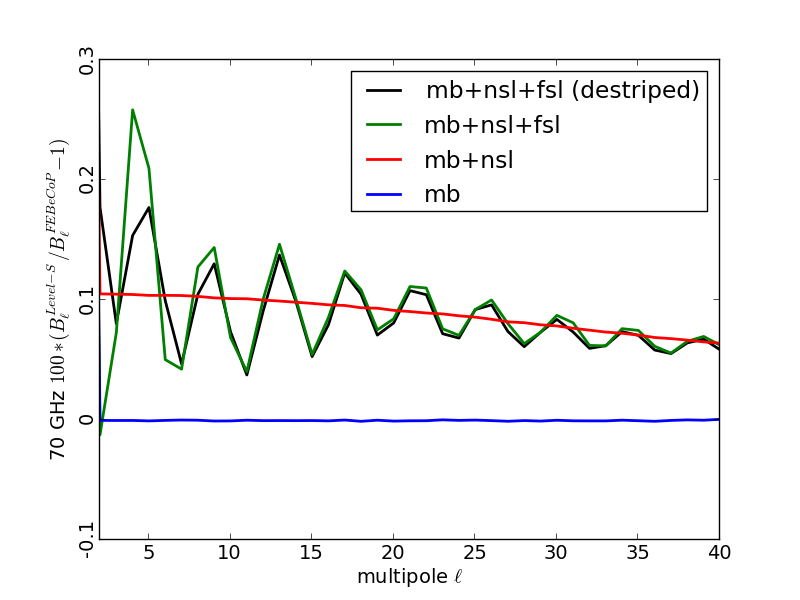
No filter function appears in Eq. (2) since the LFI analysis uses no filtering (see Poutanen et al. (2004) for destriping and filter functions). We actually obtain two output maps from Madam, the binned output map and the destriped output map. Destriping is a process that aims to remove correlated noise. It happens in the time domain and its effect does not properly belong to the beam window function, so we have used the binned output maps for calculating the window functions. For the main beam and near sidelobe timelines destriping has a rather small effect for our noiseless simulation. There is a small noiselike contribution due to pixelization noise (Kurki-Suonio et al. 2009). However, for the far sidelobe timelines, a given location of the sky appears completely different with different beam orientations, and the Madam destriper interprets this difference as due to noise and tries to remove it. Therefore the contribution of far sidelobes to the destriped maps is very different from their contribution to the binned maps. To show this effect we have also calculated the beam window functions for the full beam using the destriped maps.
To summarize, for each frequency channel and horn pair, the beam window functions have been computed for:
-
(a)
just the main beam;
-
(b)
main beam + near sidelobes;
-
(c)
main beam + near sidelobes + far sidelobes.
For the last case we calculated both a “binned” and “destriped” window function.
A comparison of the resulting window functions to the FEBeCoP window functions is shown in Fig. 15 for the 70 GHz channel. The sidelobe impact on the low multipoles for the 30 GHz channels is of nearly the same magnitude, whereas it is much lower at 44 GHz, since the main beam efficiency is higher.
 |
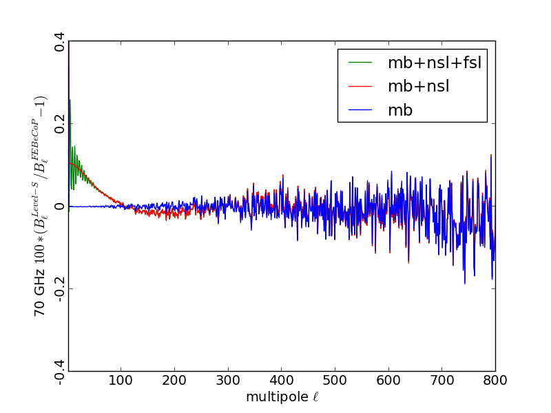 |
The increment at the quadrupole of the window functions computed considering the near sidelobes reflects the efficiencies in Table 1, i.e., about 0.1%. Since the far sidelobes are very wide structures that are strongest in a direction almost orthogonal to the line of sight, they add power incoherently to the signal entering the main beam at scales of = 2 or higher multipoles.
This timeline-to-map Monte-Carlo approach is quite resource intensive, and since the timelines are communicated from Level-S to Madam by writing them on disk from where Madam reads them, there is an I/O bottleneck that limits massive parallelization of the simulations. The FEBeCoP algorithm is much faster, hence it allows for a significantly larger number of simulations, resulting in a more accurate estimation of the window functions. Since FEBeCoP cannot handle the sidelobes, the sidelobe effect is included in the error budget, as done in the previous release.
5.3 Matrix window functions
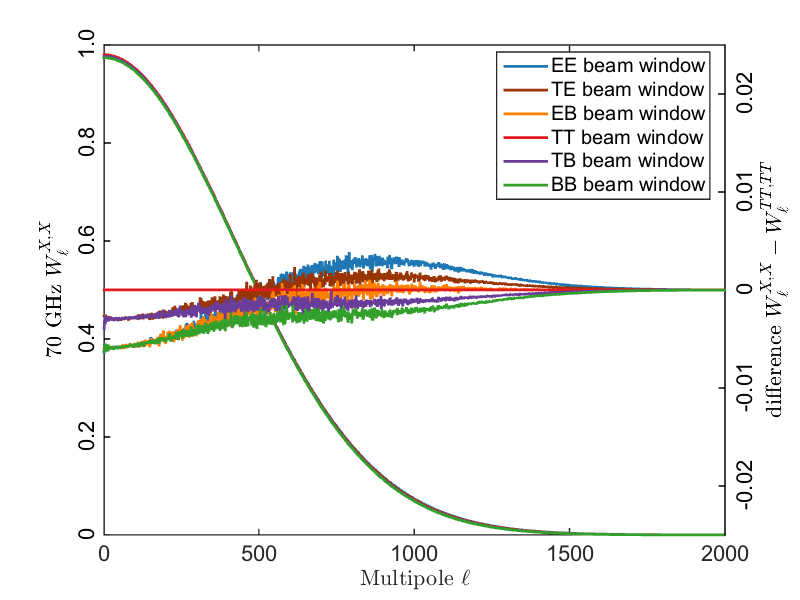
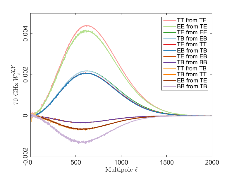
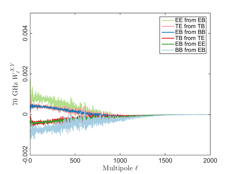
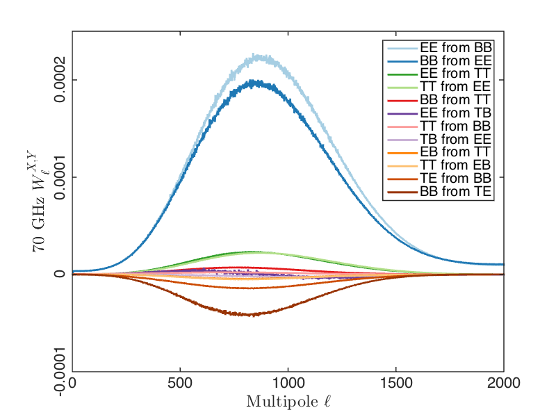
The scalar window functions of the previous subsections depend on the assumed CMB angular power spectra, in addition to the instrument beam and scanning, because they contain contributions from the leakage between the temperature and polarization signals. This gives a large contribution for the window function particularly. This is because the window function is obtained from the ratio between the (simulated) output spectrum and the input spectrum; however, because of to leakage, the output spectrum also depends on the input spectrum. We can isolate the leakage effect by introducing the matrix beam window function.
Assume that the spherical harmonic coefficients of the output map are related to those of the sky, , by
| (3) |
where . For the expectation value of the angular power spectrum of the map we then get
| (4) |
where
| (5) |
and
| (6) |
is the expectation value of the angular power spectrum of the sky.
Assuming the only effect is that of the instrument beams, the is the matrix beam window function (as formulated here, it also includes the pixel window). It should be a combined property of the beams and the scanning strategy that determines the beam orientations at different times, and independent of the angular power spectrum. We evaluate it by timeline-to-map simulations where the input skies are realizations of constant (as a function of ) . (Using realistic here would result in poor accuracy due to some being very small, especially near where the cross-correlations change sign.) We used and to produce a set of 25 realizations of , , .
To evaluate the individual matrix elements, we need three separate simulations where the input sky contains only , only , and only . We carried out such timeline-to-map simulations using the prescription of Sect. 5.2, but always setting two of the input , , to zero.
From the output maps of these simulations we get directly those matrix elements that represent leakage from , and as, e.g.,
| (7) |
We note that “-only” represents here the output map obtained from a -only input sky, not that the output map itself would have only – the presence of and in this output map is precisely due to the leakage we want to measure.
To get those matrix elements that represent the additional effect of the correlations, e.g., , we also need output maps where both and were present in the input sky. Because of the linearity of the map-making process we obtain these directly by taking the sum of the “-only” and “-only” maps. We then get
| (8) |
The evaluation of the matrix beam window functions is three times as costly as evaluating the scalar window functions. Therefore we only used 25 realizations to estimate them. This took 500 000 core-hours, the sidelobes being more costly than the main beam. Of this multimod used about 60 % and Madam about 40 %; all other steps, including conviqt_v4 and anafast, took less than 1 % taken together. (The 50 realizations for the scalar window functions took 300 000 core-hours.) The simulations were run on the CSC Sisu Cray-XC30 (Intel Haswell 2.6 GHz) computer, using 1728 cores (72 nodes), which allowed running four 70 GHz Madam map making tasks simultaneously. A larger number of simultaneous map making tasks would have led to I/O congestion. Therefore these simulations took several weeks to run.
We show all 36 components of the 70 GHz main beam matrix window function in Fig. 16. The relative effect of the near sidelobes on the diagonal components is less than or (at the lowest multipoles) roughly equal to . The relative effect of the near sidelobes to the off-diagonal components is largest where the off-diagonal components are small; the absolute effect is less than or (at the lowest multipoles) roughly equal .
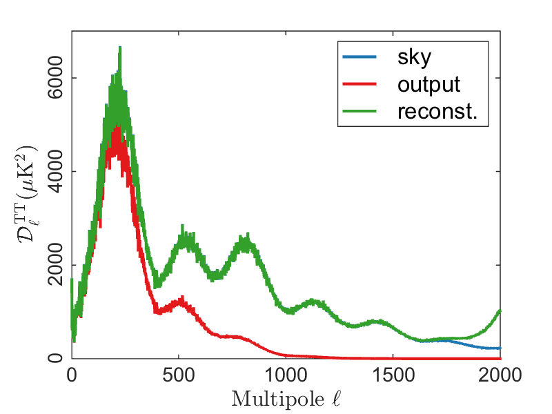
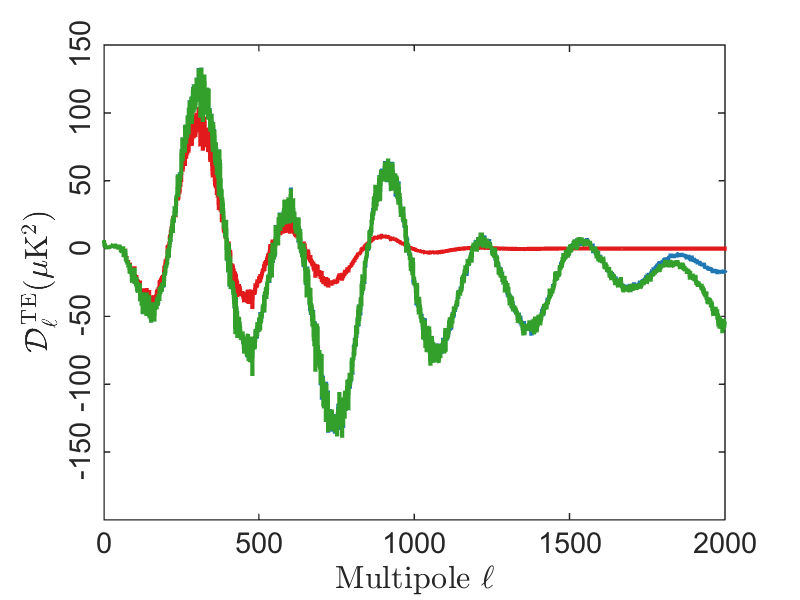
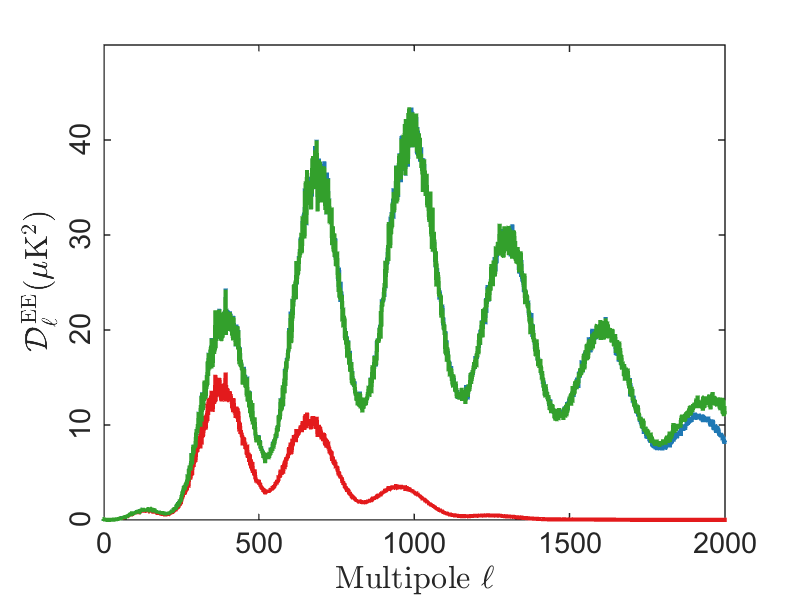
In Fig. 17 we apply the obtained inverse window function to the output of the 50th realization of our CMB simulation (Sect. 5.2) to reconstruct the input . We see that the reconstruction works for , , and to the accuracy of simulation variance, except at the highest multipoles, where the window function is very small and not calculated as accurately as for the lower multipoles. For 30 GHz and 44 GHz the performance is similar, except that the accuracy falls at lower reflecting the wider beams.
The matrix window function approach presented in this section is work in progress; it was not yet mature enough to be used later in the analysis due to the lack of further testing in the pipeline. We are working on this approach to consolidate it for future data releases.
 |
 |
 |
 |
|
6 Error budget
The propagation of the uncertainties in the beam knowledge to the window function has been evaluated using the simulated beams derived from the MC pipeline on the Planck optics performed for the last release (Planck Collaboration IV 2014). Of course, the selected sample is smaller because the uncertainties in the main beam parameters are smaller (see Table 2) with respect to those presented in the 2013 paper. Since the difference between the window functions obtained with FEBeCoP and those obtained with the simple harmonic transformation is very small (less than the error on the window function calculated in 2013), it was decided to calculate the error budget using the harmonic transform approach instead of FEBeCoP because it is much faster. This assumption is conservative (the errors calculated in this way are slightly higher than those calculated with FEBeCoP).
Using the set of simulated beam window functions, we have built the covariance matrix in -space computing
| (9) |
where the 65 simulations are averaged. Then we have decomposed the covariance matrix into eigenvalues () and eigenvectors (). The error content is substantially encompassed in the first two eigenvalues, which account for the cutoff radius and main beam uncertainties, respectively.
The FEBeCoP window functions are computed using only the main beam. In Sect. 5.2 we evaluated the impact on the beam window functions of neglecting near and far sidelobes. To evaluate the total error budget, we added this term as the first eigenmode in error decomposition described above and we show the total error budget in Figs. 18, 19, and 20 for the 70, 44, and 30 GHz, respectively. The grey line (eigenvector ) represents the cutoff radius term. The widening of the error at low accounts for the uncertainty introduced neglecting the near and far sidelobe contribution. Since for this release the new window functions are not normalized, the errors themselves are not normalized to zero.
Whereas the main beam shape has been verified via the Jupiter observations, we have no direct measurement of the near and far sidelobes. The LFI sidelobes have been computed using GRASP and taking into account the nominal radiometer bandshapes. The impact on sidelobes of the uncertainty in the knowledge of the radiometer bandshape is under investigation and will be introduced in the next release.


The LFI beams are not used in the 2015 likelihood at high (Planck Collaboration XI 2015), nevertheless we decide to estimate the impact of the beam error on the cosmological parameters. As done in 2013 release we apply the Markov Chain Beam Randomization (Rocha et al. (2010)) procedure to a simulated 70 GHz dataset. We found that the impact for all the CDM parameters is well below of confirming that the uncertainty on beam knowledge is negligible in the cosmological parameter estimation.
7 Conclusions
In this paper we discussed: (i) the improvement in the LFI main beam reconstruction with respect to the 2013 release; (ii) the beam normalization convention adopted in the LFI pipeline; (iii) the temperature and polarized beam window functions; and (iv) the error budgets on the beam parameters and window functions. The in-flight assessment of the LFI main beams relied mainly on the measurements performed during seven Jupiter crossings, the first four transits occurring in nominal scan mode and the last three scans in deep mode. The calibrated data from the Jupiter scans were used to determine the scanning beams: the signal-to-noise ratio for these data makes it possible to follow the LFI beams profile down to –30 dB. These measurements have been used to further validate the beam model presented in 2013 (GRASP beams properly smeared to take into account the satellite motion). Fitting the main beam shapes with an elliptical Gaussian, we expressed the uncertainties of the measured scanning beam in terms of statistical errors for the Gaussian parameters: ellipticity; orientation; and FWHM. The polarized beams, described in Sect. 3.2, provide the best fit to the available measurements of the LFI main beams from Jupiter. We found that this model represents all the LFI beams with an accuracy of about 0.1% at 30 and 70 GHz, and 0.2% at 44 GHz (rms value of the difference between measurements and simulations, computed within the 20 dB contour), which has been considered in the propagation of the uncertainties at the window function level. The corresponding simulated sidelobes have been used in the calibration pipeline to evaluate the gains and to subtract Galactic straylight from the calibrated timelines (Planck Collaboration II 2015). This model, together with the pointing information derived from the focal plane geometry reconstruction, gives the most advanced and precise noise-free representation of the LFI beams. The polarized beams were the input to calculate the effective beams, which take into account the specific scanning strategy to include any smearing and orientation effects on the beams themselves.
To evaluate the beam window function, we adopted two independent approaches, both based on Monte Carlo simulations. In one case, we convolved a fiducial model with realistic scanning beams in harmonic space to generate the corresponding timelines and maps; in the other case, we convolved the maps derived from the fiducial model with effective beams in pixel space. Using the first approach, we have also evaluated the contribution of the near and far sidelobes on the window functions: it is seen that the impact of sidelobes on the low multipole region is at about the 0.1 % level.
The error budget comes from two contributions: the propagation of the main beam uncertainties through the analysis; and the contribution of near and far sidelobes. As found in the past release, the two error sources have different relevance, depending on the angular scale. Ignoring the near and far sidelobes is the dominant error at low multipoles, while the main beam uncertainties dominate the total error budget at . The total uncertainties in the effective beam window functions are: 0.7% and 1% at 30 and 44 GHz, respectively (at ); and 0.5% at 70 GHz at .
The results presented in this paper, and in the LFI companion papers, prove the extraordinary capabilities of LFI in achieving the expected objectives in terms of sensitivity, angular resolution, and control of systematic effects. In particular, we found an impressive consistency between main beam simulations and measurements, which demonstrates the reliability and the accuracy of the optical model. The methods used to evaluate the beam window functions and the corresponding error budget have proved to be very well consolidated. In addition, a new promising approach – the matrix beam window function – has been presented and it will be consolidated for future data releases.
Acknowledgements.
Planck is too large a project to allow full acknowledgement of all contributions by individuals, institutions, industries, and funding agencies. The main entities involved in the mission operations are as follows. The European Space Agency (ESA) operates the satellite via its Mission Operations Centre located at ESOC (Darmstadt, Germany) and coordinates scientific operations via the Planck Science Office located at ESAC (Madrid, Spain). Two Consortia, comprising around 50 scientific institutes within Europe, the USA, and Canada, and funded by agencies from the participating countries, developed the scientific instruments LFI and HFI, and continue to operate them via Instrument Operations Teams located in Trieste (Italy) and Orsay (France). The Consortia are also responsible for scientific processing of the acquired data. The Consortia are led by the Principal Investigators: J.L. Puget in France for HFI (funded principally by CNES and CNRS/INSU-IN2P3-INP) and N. Mandolesi in Italy for LFI (funded principally via ASI). NASA US Planck Project, based at JPL and involving scientists at many US institutions, contributes significantly to the efforts of these two Consortia. The author list for this paper has been selected by the Planck Science Team, and is composed of individuals from all of the above entities who have made multi-year contributions to the development of the mission. It does not pretend to be inclusive of all contributions. The Planck-LFI project is developed by an International Consortium led by Italy and involving Canada, Finland, Germany, Norway, Spain, Switzerland, UK, and USA. The Italian contribution to Planck is supported by the Italian Space Agency (ASI) and INAF. This work was supported by the Academy of Finland grants 253204, 256265, 257989, and 283497. We acknowledge that the results of this research have been achieved using the PRACE-3IP project (FP7 RI-312763) resource Sisu based in Finland at CSC. We thank CSC – IT Center for Science Ltd (Finland) for computational resources. We acknowledge financial support provided by the Spanish Ministerio de Ciencia e Innovaciõn through the Plan Nacional del Espacio y Plan Nacional de Astronomia y Astrofisica. We acknowledge the Max Planck Institute for Astrophysics Planck Analysis Centre (MPAC), funded by the Space Agency of the German Aerospace Center (DLR) under grant 50OP0901 with resources of the German Federal Ministry of Economics and Technology, and by the Max Planck Society. This work has made use of the Planck satellite simulation package (Level-S), which is assembled by the Max Planck Institute for Astrophysics Planck Analysis Centre (MPAC). We acknowledge financial support provided by the National Energy Research Scientific Computing Center, which is supported by the Office of Science of the U.S. Department of Energy under Contract No. DE-AC02-05CH11231. Some of the results in this paper have been derived using the HEALPix package. The Planck Collaboration acknowledges the support of: ESA; CNES and CNRS/INSU-IN2P3-INP (France); ASI, CNR, and INAF (Italy); NASA and DoE (USA); STFC and UKSA (UK); CSIC, MINECO, JA, and RES (Spain); Tekes, AoF, and CSC (Finland); DLR and MPG (Germany); CSA (Canada); DTU Space (Denmark); SER/SSO (Switzerland); RCN (Norway); SFI (Ireland); FCT/MCTES (Portugal); ERC and PRACE (EU). A description of the Planck Collaboration and a list of its members, indicating which technical or scientific activities they have been involved in, can be found at http://www.cosmos.esa.int/web/planck/planck-collaboration.Appendix A Useful definitions
A.1 GRASP simulations
The far field pattern in the three regions reported above has been computed with GRASP using different computational methods and different field storage.
Main beams have been computed in two-dimensional grids over the spherical surface, defined by the variables u and v, related to the spherical angles by u = and v = . The variables u and v range from –0.033 to 0.033 () for the 30 GHz channel, from –0.023 to 0.023 () for the 44 GHz channels, and from –0.015 to 0.015 () for the 70 GHz channel. Each grid is sampled with 601 601 points, therefore the spatial resolution is about 23 arcsec for the 30 GHz channel, 16 arcsec for the 44 GHz channel, and 10 arcsec for the 70 GHz channel.
Near and far sidelobes have been computed in spherical polar cuts, for which is constant and is varying. These cuts pass through the pole of the sphere (i.e., the beam pointing direction) at . Near sidelobes have been computed with a spatial resolution of 1’ in and 0.5∘ in . Far sidelobes have been computed with a spatial resolution of 0.5∘, both in and .
Main beams and near sidelobes have been computed using physical optics and physical theory of diffraction (Ticra 2008), whereas far sidelobes have been computed using Multi-reflector Geometrical Theory of Diffraction (MrGTD) (Ticra 2012).

A.2 Nomenclature for beams
In the present paper, and in the Planck companion papers, we used three relevant definitions:
-
1.
The “optical beam” is the optical response of the feed horn coupled to the telescope. It is independent of both the radiometer response (bandshape and non-linearity) and of the satellite motion (spinning and scanning strategy). It represents the pure optical transfer function. The main beam properties of the optical beams can be evaluated using optical simulations performed with methods largely validated by ground measurements.
-
2.
The “scanning beam” is the beam that can be directly measured in-flight using planet observations. It stems from the optical beam, coupled with the radiometer response, and smeared by the satellite motion. So, with respect to the optical beams, the scanning beams have slightly higher values of angular size and ellipticity.
-
3.
The “effective beam” is a beam defined in the map-domain, and is obtained by averaging the scanning beams pointing at a given pixel of the map, taking into account the scanning strategy and the orientation of the beams themselves when they point along the direction to that pixel. Therefore, whereas for each radiometer there is one corresponding optical and scanning beam, the same radiometer has the same number of effective beams as there are pixels in the observed sky map. The importance of the effective beams is twofold: they are used in the window function computation; and their solid angles are needed for the estimation of the flux density of point sources.
Appendix B Beam fit results
As described in Sect. 3.1, the code used to fit the beam shape to an elliptical Gaussian function returns the full width half maximum (FWHM), the beam ellipticity (), and the beam orientation (). Moreover, the fit procedure returns the main beam pointing directions in the Planck field of view, centred along the nominal line of sight. In Tables from 6 to 12, the fitted parameters are reported for each scan, with their error at 68 %CL. These values are those plotted in Figs. 4, 5, and 6. The main beam descriptive parameters fitted from the stacked scans are those reported in Table 2, whereas the main beam pointing directions ( and ) have been computed from and , and reported in Planck Collaboration II (2015), using these simple formulae:
| (10) |
| (11) |
| Beam | X0 | Y0 | FWHM | e | ||||||||||||||
| (arcmin) | (deg) | |||||||||||||||||
| 70 GHz | ||||||||||||||||||
| 18M | –0. | 03879 | 0. | 00002 | –0. | 04334 | 0. | 00002 | 13. | 44 | 0. | 13 | 1. | 23 | 0. | 02 | 85 | 2 |
| 18S | –0. | 03878 | 0. | 00002 | –0. | 04335 | 0. | 00002 | 13. | 50 | 0. | 12 | 1. | 27 | 0. | 02 | 86 | 2 |
| 19M | –0. | 04873 | 0. | 00002 | –0. | 02759 | 0. | 00002 | 13. | 14 | 0. | 13 | 1. | 25 | 0. | 02 | 78 | 2 |
| 19S | –0. | 04874 | 0. | 00002 | –0. | 02758 | 0. | 00002 | 13. | 07 | 0. | 13 | 1. | 28 | 0. | 02 | 79 | 2 |
| 20M | –0. | 05438 | 0. | 00002 | –0. | 01138 | 0. | 00002 | 12. | 84 | 0. | 12 | 1. | 27 | 0. | 02 | 71 | 2 |
| 20S | –0. | 05438 | 0. | 00002 | –0. | 01137 | 0. | 00002 | 12. | 84 | 0. | 13 | 1. | 29 | 0. | 02 | 72 | 2 |
| 21M | –0. | 05460 | 0. | 00002 | 0. | 01034 | 0. | 00002 | 12. | 77 | 0. | 10 | 1. | 28 | 0. | 02 | 107 | 1 |
| 21S | –0. | 05459 | 0. | 00002 | 0. | 01035 | 0. | 00002 | 12. | 87 | 0. | 12 | 1. | 29 | 0. | 02 | 106 | 2 |
| 22M | –0. | 04860 | 0. | 00002 | 0. | 02654 | 0. | 00002 | 12. | 92 | 0. | 11 | 1. | 27 | 0. | 01 | 101 | 2 |
| 22S | –0. | 04861 | 0. | 00002 | 0. | 02653 | 0. | 00002 | 12. | 97 | 0. | 12 | 1. | 28 | 0. | 02 | 101 | 2 |
| 23M | –0. | 03849 | 0. | 00002 | 0. | 04237 | 0. | 00002 | 13. | 35 | 0. | 12 | 1. | 23 | 0. | 02 | 92 | 2 |
| 23S | –0. | 03850 | 0. | 00002 | 0. | 04235 | 0. | 00002 | 13. | 36 | 0. | 13 | 1. | 28 | 0. | 02 | 92 | 2 |
| 44 GHz | ||||||||||||||||||
| 24M | –0. | 07102 | 0. | 00007 | –0. | 00058 | 0. | 00009 | 23. | 18 | 0. | 51 | 1. | 39 | 0. | 06 | 89 | 3 |
| 24S | –0. | 07101 | 0. | 00006 | –0. | 00060 | 0. | 00008 | 23. | 04 | 0. | 45 | 1. | 34 | 0. | 05 | 89 | 3 |
| 25M | 0. | 04199 | 0. | 00014 | 0. | 07605 | 0. | 00012 | 30. | 23 | 0. | 94 | 1. | 19 | 0. | 07 | 114 | 9 |
| 25S | 0. | 04193 | 0. | 00015 | 0. | 07607 | 0. | 00012 | 30. | 94 | 0. | 95 | 1. | 19 | 0. | 07 | 117 | 9 |
| 26M | 0. | 04165 | 0. | 00016 | –0. | 07727 | 0. | 00013 | 30. | 29 | 1. | 06 | 1. | 19 | 0. | 08 | 62 | 10 |
| 26S | 0. | 04163 | 0. | 00015 | –0. | 07728 | 0. | 00012 | 30. | 64 | 0. | 97 | 1. | 19 | 0. | 07 | 61 | 9 |
| 30 GHz | ||||||||||||||||||
| 27M | –0. | 06810 | 0. | 00014 | 0. | 03326 | 0. | 00019 | 33. | 02 | 1. | 09 | 1. | 37 | 0. | 05 | 101 | 5 |
| 27S | –0. | 06811 | 0. | 00014 | 0. | 03326 | 0. | 00019 | 33. | 11 | 1. | 13 | 1. | 38 | 0. | 05 | 101 | 5 |
| 28M | –0. | 06823 | 0. | 00015 | –0. | 03412 | 0. | 00020 | 33. | 10 | 1. | 18 | 1. | 37 | 0. | 05 | 78 | 5 |
| 28S | –0. | 06825 | 0. | 00014 | –0. | 03412 | 0. | 00018 | 33. | 09 | 1. | 08 | 1. | 37 | 0. | 05 | 78 | 5 |
| Beam | X0 | Y0 | FWHM | e | ||||||||||||||
| (arcmin) | (deg) | |||||||||||||||||
| 70 GHz | ||||||||||||||||||
| 18M | –0. | 03879 | 0. | 00002 | –0. | 04334 | 0. | 00002 | 13. | 40 | 0. | 11 | 1. | 23 | 0. | 02 | 85 | 2 |
| 18S | –0. | 03879 | 0. | 00002 | –0. | 04334 | 0. | 00002 | 13. | 45 | 0. | 10 | 1. | 28 | 0. | 02 | 86 | 1 |
| 19M | –0. | 04872 | 0. | 00002 | –0. | 02758 | 0. | 00002 | 13. | 13 | 0. | 11 | 1. | 25 | 0. | 02 | 78 | 2 |
| 19S | –0. | 04873 | 0. | 00002 | –0. | 02758 | 0. | 00002 | 13. | 08 | 0. | 11 | 1. | 28 | 0. | 02 | 79 | 1 |
| 20M | –0. | 05438 | 0. | 00002 | –0. | 01137 | 0. | 00002 | 12. | 81 | 0. | 10 | 1. | 27 | 0. | 02 | 71 | 1 |
| 20S | –0. | 05438 | 0. | 00002 | –0. | 01136 | 0. | 00002 | 12. | 83 | 0. | 11 | 1. | 29 | 0. | 02 | 72 | 1 |
| 21M | –0. | 05461 | 0. | 00001 | 0. | 01034 | 0. | 00002 | 12. | 74 | 0. | 09 | 1. | 28 | 0. | 02 | 108 | 1 |
| 21S | –0. | 05459 | 0. | 00002 | 0. | 01035 | 0. | 00002 | 12. | 86 | 0. | 10 | 1. | 29 | 0. | 02 | 106 | 1 |
| 22M | –0. | 04859 | 0. | 00001 | 0. | 02654 | 0. | 00002 | 12. | 89 | 0. | 09 | 1. | 26 | 0. | 02 | 101 | 1 |
| 22S | –0. | 04859 | 0. | 00001 | 0. | 02653 | 0. | 00002 | 12. | 95 | 0. | 10 | 1. | 28 | 0. | 02 | 101 | 1 |
| 23M | –0. | 03849 | 0. | 00002 | 0. | 04237 | 0. | 00002 | 13. | 32 | 0. | 11 | 1. | 24 | 0. | 02 | 93 | 2 |
| 23S | –0. | 03850 | 0. | 00002 | 0. | 04235 | 0. | 00002 | 13. | 32 | 0. | 11 | 1. | 28 | 0. | 02 | 93 | 1 |
| 44 GHz | ||||||||||||||||||
| 24M | –0. | 07102 | 0. | 00006 | –0. | 00057 | 0. | 00008 | 23. | 18 | 0. | 44 | 1. | 39 | 0. | 05 | 90 | 3 |
| 24S | –0. | 07100 | 0. | 00005 | –0. | 00062 | 0. | 00007 | 23. | 04 | 0. | 40 | 1. | 34 | 0. | 04 | 90 | 3 |
| 25M | 0. | 04201 | 0. | 00012 | 0. | 07605 | 0. | 00010 | 30. | 16 | 0. | 80 | 1. | 19 | 0. | 06 | 115 | 7 |
| 25S | 0. | 04196 | 0. | 00013 | 0. | 07607 | 0. | 00011 | 30. | 88 | 0. | 81 | 1. | 19 | 0. | 06 | 116 | 7 |
| 26M | 0. | 04166 | 0. | 00014 | –0. | 07727 | 0. | 00011 | 30. | 16 | 0. | 91 | 1. | 19 | 0. | 07 | 62 | 8 |
| 26S | 0. | 04165 | 0. | 00013 | –0. | 07728 | 0. | 00011 | 30. | 50 | 0. | 83 | 1. | 19 | 0. | 06 | 61 | 8 |
| 30 GHz | ||||||||||||||||||
| 27M | –0. | 06810 | 0. | 00012 | 0. | 03323 | 0. | 00016 | 33. | 03 | 0. | 93 | 1. | 36 | 0. | 04 | 101 | 4 |
| 27S | –0. | 06810 | 0. | 00012 | 0. | 03324 | 0. | 00017 | 33. | 25 | 0. | 99 | 1. | 38 | 0. | 04 | 101 | 4 |
| 28M | –0. | 06825 | 0. | 00013 | –0. | 03413 | 0. | 00017 | 33. | 16 | 1. | 02 | 1. | 37 | 0. | 04 | 78 | 5 |
| 28S | –0. | 06823 | 0. | 00012 | –0. | 03415 | 0. | 00016 | 33. | 20 | 0. | 93 | 1. | 37 | 0. | 04 | 78 | 4 |
| Beam | X0 | Y0 | FWHM | e | ||||||||||||||
| (arcmin) | (deg) | |||||||||||||||||
| 70 GHz | ||||||||||||||||||
| 18M | –0. | 03878 | 0. | 00002 | –0. | 04334 | 0. | 00002 | 13. | 40 | 0. | 11 | 1. | 24 | 0. | 02 | 85 | 2 |
| 18S | –0. | 03878 | 0. | 00002 | –0. | 04334 | 0. | 00002 | 13. | 46 | 0. | 10 | 1. | 28 | 0. | 02 | 86 | 1 |
| 19M | –0. | 04871 | 0. | 00002 | –0. | 02758 | 0. | 00002 | 13. | 13 | 0. | 11 | 1. | 25 | 0. | 02 | 79 | 2 |
| 19S | –0. | 04872 | 0. | 00002 | –0. | 02758 | 0. | 00002 | 13. | 10 | 0. | 11 | 1. | 28 | 0. | 02 | 79 | 1 |
| 20M | –0. | 05437 | 0. | 00002 | –0. | 01138 | 0. | 00002 | 12. | 83 | 0. | 11 | 1. | 27 | 0. | 02 | 71 | 1 |
| 20S | –0. | 05437 | 0. | 00002 | –0. | 01137 | 0. | 00002 | 12. | 84 | 0. | 11 | 1. | 29 | 0. | 02 | 72 | 1 |
| 21M | –0. | 05460 | 0. | 00001 | 0. | 01034 | 0. | 00002 | 12. | 77 | 0. | 09 | 1. | 28 | 0. | 02 | 107 | 1 |
| 21S | –0. | 05458 | 0. | 00002 | 0. | 01035 | 0. | 00002 | 12. | 87 | 0. | 10 | 1. | 30 | 0. | 02 | 106 | 1 |
| 22M | –0. | 04858 | 0. | 00001 | 0. | 02654 | 0. | 00002 | 12. | 92 | 0. | 09 | 1. | 27 | 0. | 02 | 102 | 1 |
| 22S | –0. | 04859 | 0. | 00001 | 0. | 02653 | 0. | 00002 | 12. | 99 | 0. | 10 | 1. | 28 | 0. | 02 | 101 | 1 |
| 23M | –0. | 03849 | 0. | 00002 | 0. | 04236 | 0. | 00002 | 13. | 32 | 0. | 11 | 1. | 24 | 0. | 02 | 93 | 2 |
| 23S | –0. | 03850 | 0. | 00002 | 0. | 04235 | 0. | 00002 | 13. | 33 | 0. | 11 | 1. | 28 | 0. | 02 | 93 | 1 |
| 44 GHz | ||||||||||||||||||
| 24M | –0. | 07101 | 0. | 00006 | –0. | 00057 | 0. | 00008 | 23. | 20 | 0. | 44 | 1. | 39 | 0. | 05 | 89 | 3 |
| 24S | –0. | 07099 | 0. | 00005 | –0. | 00062 | 0. | 00007 | 23. | 16 | 0. | 40 | 1. | 34 | 0. | 04 | 89 | 3 |
| 25M | 0. | 04198 | 0. | 00012 | 0. | 07605 | 0. | 00010 | 30. | 15 | 0. | 76 | 1. | 19 | 0. | 06 | 115 | 7 |
| 25S | 0. | 04194 | 0. | 00012 | 0. | 07606 | 0. | 00010 | 30. | 91 | 0. | 77 | 1. | 19 | 0. | 05 | 117 | 7 |
| 26M | 0. | 04165 | 0. | 00013 | –0. | 07726 | 0. | 00011 | 30. | 26 | 0. | 87 | 1. | 19 | 0. | 06 | 61 | 8 |
| 26S | 0. | 04166 | 0. | 00012 | –0. | 07726 | 0. | 00010 | 30. | 62 | 0. | 79 | 1. | 19 | 0. | 06 | 62 | 7 |
| 30 GHz | ||||||||||||||||||
| 27M | –0. | 06810 | 0. | 00012 | 0. | 03322 | 0. | 00016 | 33. | 13 | 0. | 92 | 1. | 37 | 0. | 04 | 101 | 4 |
| 27S | –0. | 06810 | 0. | 00012 | 0. | 03322 | 0. | 00016 | 33. | 30 | 0. | 97 | 1. | 37 | 0. | 04 | 101 | 4 |
| 28M | –0. | 06823 | 0. | 00013 | –0. | 03414 | 0. | 00017 | 33. | 32 | 1. | 03 | 1. | 37 | 0. | 08 | 78 | 5 |
| 28S | –0. | 06822 | 0. | 00012 | –0. | 03414 | 0. | 00016 | 33. | 24 | 0. | 93 | 1. | 36 | 0. | 04 | 78 | 4 |
| Beam | X0 | Y0 | FWHM | e | ||||||||||||||
| (arcmin) | (deg) | |||||||||||||||||
| 70 GHz | ||||||||||||||||||
| 18M | –0. | 03878 | 0. | 00002 | –0. | 04333 | 0. | 00003 | 13. | 39 | 0. | 14 | 1. | 24 | 0. | 03 | 85 | 2 |
| 18S | –0. | 03878 | 0. | 00002 | –0. | 04334 | 0. | 00003 | 13. | 46 | 0. | 14 | 1. | 28 | 0. | 03 | 86 | 2 |
| 19M | –0. | 04872 | 0. | 00002 | –0. | 02758 | 0. | 00003 | 13. | 13 | 0. | 15 | 1. | 25 | 0. | 03 | 79 | 2 |
| 19S | –0. | 04872 | 0. | 00002 | –0. | 02757 | 0. | 00003 | 13. | 07 | 0. | 14 | 1. | 28 | 0. | 03 | 79 | 2 |
| 20M | –0. | 05437 | 0. | 00002 | –0. | 01137 | 0. | 00003 | 12. | 84 | 0. | 14 | 1. | 27 | 0. | 03 | 71 | 2 |
| 20S | –0. | 05438 | 0. | 00002 | –0. | 01136 | 0. | 00003 | 12. | 83 | 0. | 15 | 1. | 29 | 0. | 03 | 72 | 2 |
| 21M | –0. | 05460 | 0. | 00002 | 0. | 01035 | 0. | 00002 | 12. | 75 | 0. | 12 | 1. | 28 | 0. | 02 | 108 | 2 |
| 21S | –0. | 05459 | 0. | 00002 | 0. | 01035 | 0. | 00003 | 12. | 87 | 0. | 14 | 1. | 29 | 0. | 03 | 106 | 2 |
| 22M | –0. | 04858 | 0. | 00002 | 0. | 02654 | 0. | 00002 | 12. | 92 | 0. | 13 | 1. | 26 | 0. | 02 | 101 | 2 |
| 22S | –0. | 04859 | 0. | 00002 | 0. | 02654 | 0. | 00003 | 12. | 99 | 0. | 13 | 1. | 28 | 0. | 03 | 101 | 2 |
| 23M | –0. | 03849 | 0. | 00002 | 0. | 04238 | 0. | 00003 | 13. | 32 | 0. | 14 | 1. | 24 | 0. | 03 | 93 | 2 |
| 23S | –0. | 03850 | 0. | 00002 | 0. | 04236 | 0. | 00003 | 13. | 33 | 0. | 15 | 1. | 28 | 0. | 03 | 93 | 2 |
| 44 GHz | ||||||||||||||||||
| 24M | –0. | 07101 | 0. | 00008 | –0. | 00056 | 0. | 00011 | 23. | 16 | 0. | 60 | 1. | 39 | 0. | 07 | 90 | 4 |
| 24S | –0. | 07099 | 0. | 00007 | –0. | 00061 | 0. | 00010 | 23. | 02 | 0. | 54 | 1. | 34 | 0. | 06 | 90 | 4 |
| 25M | 0. | 04200 | 0. | 00016 | 0. | 07604 | 0. | 00014 | 30. | 24 | 1. | 06 | 1. | 20 | 0. | 08 | 116 | 10 |
| 25S | 0. | 04194 | 0. | 00016 | 0. | 07606 | 0. | 00014 | 31. | 01 | 1. | 09 | 1. | 19 | 0. | 08 | 117 | 10 |
| 26M | 0. | 04167 | 0. | 00018 | –0. | 07726 | 0. | 00015 | 30. | 23 | 1. | 22 | 1. | 20 | 0. | 09 | 60 | 11 |
| 26S | 0. | 04167 | 0. | 00017 | –0. | 07728 | 0. | 00014 | 30. | 69 | 1. | 12 | 1. | 19 | 0. | 08 | 61 | 10 |
| 30 GHz | ||||||||||||||||||
| 27M | –0. | 06810 | 0. | 00016 | 0. | 03323 | 0. | 00022 | 33. | 00 | 1. | 28 | 1. | 36 | 0. | 05 | 101 | 6 |
| 27S | –0. | 06810 | 0. | 00017 | 0. | 03324 | 0. | 00023 | 33. | 12 | 1. | 36 | 1. | 38 | 0. | 06 | 100 | 6 |
| 28M | –0. | 06822 | 0. | 00018 | –0. | 03414 | 0. | 00024 | 33. | 19 | 1. | 45 | 1. | 37 | 0. | 11 | 78 | 7 |
| 28S | –0. | 06821 | 0. | 00017 | –0. | 03413 | 0. | 00022 | 33. | 19 | 1. | 32 | 1. | 37 | 0. | 10 | 78 | 6 |
| Beam | X0 | Y0 | FWHM | e | ||||||||||||||
|---|---|---|---|---|---|---|---|---|---|---|---|---|---|---|---|---|---|---|
| (arcmin) | (deg) | |||||||||||||||||
| 70 GHz | ||||||||||||||||||
| 18M | –0. | 03878 | 0. | 00002 | –0. | 04334 | 0. | 00002 | 13. | 39 | 0. | 12 | 1. | 24 | 0. | 02 | 85 | 2 |
| 18S | –0. | 03878 | 0. | 00002 | –0. | 04334 | 0. | 00002 | 13. | 46 | 0. | 12 | 1. | 28 | 0. | 02 | 86 | 2 |
| 19M | –0. | 04872 | 0. | 00001 | –0. | 02759 | 0. | 00001 | 13. | 13 | 0. | 06 | 1. | 25 | 0. | 01 | 78 | 1 |
| 19S | –0. | 04872 | 0. | 00001 | –0. | 02758 | 0. | 00001 | 13. | 08 | 0. | 05 | 1. | 28 | 0. | 01 | 79 | 1 |
| 20M | –0. | 05437 | 0. | 00001 | –0. | 01138 | 0. | 00001 | 12. | 82 | 0. | 05 | 1. | 27 | 0. | 01 | 71 | 1 |
| 20S | –0. | 05438 | 0. | 00001 | –0. | 01137 | 0. | 00001 | 12. | 83 | 0. | 05 | 1. | 29 | 0. | 01 | 72 | 1 |
| 21M | –0. | 05460 | 0. | 00001 | 0. | 01034 | 0. | 00001 | 12. | 74 | 0. | 04 | 1. | 28 | 0. | 01 | 108 | 1 |
| 21S | –0. | 05459 | 0. | 00001 | 0. | 01035 | 0. | 00001 | 12. | 86 | 0. | 05 | 1. | 30 | 0. | 01 | 106 | 1 |
| 22M | –0. | 04859 | 0. | 00001 | 0. | 02654 | 0. | 00001 | 12. | 92 | 0. | 05 | 1. | 26 | 0. | 01 | 101 | 1 |
| 22S | –0. | 04860 | 0. | 00001 | 0. | 02653 | 0. | 00001 | 13. | 00 | 0. | 05 | 1. | 28 | 0. | 01 | 101 | 1 |
| 23M | –0. | 03849 | 0. | 00002 | 0. | 04236 | 0. | 00002 | 13. | 30 | 0. | 12 | 1. | 24 | 0. | 02 | 93 | 2 |
| 23S | –0. | 03850 | 0. | 00002 | 0. | 04235 | 0. | 00002 | 13. | 33 | 0. | 13 | 1. | 28 | 0. | 02 | 93 | 2 |
| Beam | X0 | Y0 | FWHM | e | ||||||||||||||
| (arcmin) | (deg) | |||||||||||||||||
| 70 GHz | ||||||||||||||||||
| 18M | –0. | 03879 | 0. | 00001 | –0. | 04335 | 0. | 00001 | 13. | 40 | 0. | 14 | 1. | 24 | 0. | 03 | 85 | 2 |
| 18S | –0. | 03878 | 0. | 00001 | –0. | 04336 | 0. | 00001 | 13. | 45 | 0. | 14 | 1. | 28 | 0. | 03 | 86 | 2 |
| 19M | –0. | 04872 | 0. | 00001 | –0. | 02760 | 0. | 00001 | 13. | 13 | 0. | 15 | 1. | 25 | 0. | 03 | 78 | 2 |
| 19S | –0. | 04872 | 0. | 00001 | –0. | 02759 | 0. | 00001 | 13. | 09 | 0. | 14 | 1. | 28 | 0. | 03 | 79 | 2 |
| 20M | –0. | 05437 | 0. | 00001 | –0. | 01139 | 0. | 00001 | 12. | 83 | 0. | 14 | 1. | 27 | 0. | 03 | 71 | 2 |
| 20S | –0. | 05438 | 0. | 00001 | –0. | 01138 | 0. | 00002 | 12. | 82 | 0. | 15 | 1. | 29 | 0. | 03 | 72 | 2 |
| 21M | –0. | 05461 | 0. | 00001 | 0. | 01033 | 0. | 00001 | 12. | 73 | 0. | 12 | 1. | 28 | 0. | 02 | 108 | 2 |
| 21S | –0. | 05460 | 0. | 00001 | 0. | 01034 | 0. | 00001 | 12. | 85 | 0. | 14 | 1. | 29 | 0. | 03 | 106 | 2 |
| 22M | –0. | 04859 | 0. | 00001 | 0. | 02652 | 0. | 00001 | 12. | 92 | 0. | 13 | 1. | 26 | 0. | 02 | 101 | 2 |
| 22S | –0. | 04860 | 0. | 00001 | 0. | 02652 | 0. | 00001 | 12. | 99 | 0. | 13 | 1. | 28 | 0. | 03 | 101 | 2 |
| 23M | –0. | 03849 | 0. | 00001 | 0. | 04235 | 0. | 00001 | 13. | 32 | 0. | 14 | 1. | 24 | 0. | 03 | 93 | 2 |
| 23S | –0. | 03851 | 0. | 00001 | 0. | 04234 | 0. | 00001 | 13. | 32 | 0. | 15 | 1. | 28 | 0. | 03 | 93 | 2 |
| 44 GHz | ||||||||||||||||||
| 24M | –0. | 07103 | 0. | 00007 | –0. | 00058 | 0. | 00010 | 23. | 22 | 0. | 60 | 1. | 39 | 0. | 07 | 90 | 4 |
| 24S | –0. | 07100 | 0. | 00004 | –0. | 00062 | 0. | 00006 | 22. | 91 | 0. | 54 | 1. | 34 | 0. | 06 | 90 | 4 |
| 25M | 0. | 04199 | 0. | 00012 | 0. | 07604 | 0. | 00010 | 30. | 14 | 1. | 06 | 1. | 20 | 0. | 08 | 116 | 10 |
| 25S | 0. | 04194 | 0. | 00012 | 0. | 07605 | 0. | 00010 | 31. | 00 | 1. | 09 | 1. | 19 | 0. | 08 | 117 | 10 |
| 26M | 0. | 04166 | 0. | 00013 | –0. | 07727 | 0. | 00011 | 30. | 22 | 1. | 22 | 1. | 20 | 0. | 09 | 60 | 11 |
| 26S | 0. | 04166 | 0. | 00012 | –0. | 07729 | 0. | 00011 | 30. | 70 | 1. | 12 | 1. | 19 | 0. | 08 | 61 | 10 |
| 30 GHz | ||||||||||||||||||
| 27M | –0. | 06811 | 0. | 00009 | 0. | 03322 | 0. | 00012 | 32. | 68 | 1. | 28 | 1. | 36 | 0. | 05 | 101 | 6 |
| 27S | –0. | 06810 | 0. | 00009 | 0. | 03323 | 0. | 00012 | 33. | 02 | 1. | 36 | 1. | 38 | 0. | 06 | 100 | 6 |
| 28M | –0. | 06824 | 0. | 00010 | –0. | 03414 | 0. | 00013 | 32. | 99 | 1. | 45 | 1. | 37 | 0. | 11 | 78 | 7 |
| 28S | –0. | 06823 | 0. | 00009 | –0. | 03415 | 0. | 00012 | 32. | 89 | 1. | 32 | 1. | 37 | 0. | 10 | 78 | 6 |
| Beam | X0 | Y0 | FWHM | e | ||||||||||||||
| (arcmin) | (deg) | |||||||||||||||||
| 70 GHz | ||||||||||||||||||
| 18M | –0. | 03879 | 0. | 00001 | –0. | 04333 | 0. | 00001 | 13. | 40 | 0. | 07 | 1. | 24 | 0. | 01 | 85 | 1 |
| 18S | –0. | 03878 | 0. | 00001 | –0. | 04334 | 0. | 00001 | 13. | 46 | 0. | 06 | 1. | 28 | 0. | 01 | 86 | 1 |
| 19M | –0. | 04872 | 0. | 00001 | –0. | 02758 | 0. | 00001 | 13. | 13 | 0. | 07 | 1. | 25 | 0. | 01 | 78 | 1 |
| 19S | –0. | 04872 | 0. | 00001 | –0. | 02757 | 0. | 00001 | 13. | 09 | 0. | 07 | 1. | 28 | 0. | 01 | 79 | 1 |
| 20M | –0. | 05438 | 0. | 00001 | –0. | 01137 | 0. | 00001 | 12. | 84 | 0. | 06 | 1. | 27 | 0. | 01 | 71 | 1 |
| 20S | –0. | 05438 | 0. | 00001 | –0. | 01136 | 0. | 00001 | 12. | 84 | 0. | 07 | 1. | 29 | 0. | 01 | 72 | 1 |
| 21M | –0. | 05461 | 0. | 00001 | 0. | 01034 | 0. | 00001 | 12. | 77 | 0. | 05 | 1. | 28 | 0. | 01 | 107 | 1 |
| 21S | –0. | 05460 | 0. | 00001 | 0. | 01035 | 0. | 00001 | 12. | 87 | 0. | 06 | 1. | 29 | 0. | 01 | 106 | 1 |
| 22M | –0. | 04859 | 0. | 00001 | 0. | 02654 | 0. | 00001 | 12. | 93 | 0. | 06 | 1. | 26 | 0. | 01 | 101 | 1 |
| 22S | –0. | 04860 | 0. | 00001 | 0. | 02653 | 0. | 00001 | 12. | 98 | 0. | 06 | 1. | 28 | 0. | 01 | 101 | 1 |
| 23M | –0. | 03850 | 0. | 00001 | 0. | 04237 | 0. | 00001 | 13. | 32 | 0. | 06 | 1. | 24 | 0. | 01 | 93 | 1 |
| 23S | –0. | 03851 | 0. | 00001 | 0. | 04236 | 0. | 00001 | 13. | 34 | 0. | 07 | 1. | 28 | 0. | 01 | 93 | 1 |
| 44 GHz | ||||||||||||||||||
| 24M | –0. | 07103 | 0. | 00004 | –0. | 00056 | 0. | 00005 | 23. | 28 | 0. | 27 | 1. | 39 | 0. | 03 | 89 | 1 |
| 24S | –0. | 07101 | 0. | 00003 | –0. | 00061 | 0. | 00004 | 23. | 08 | 0. | 24 | 1. | 34 | 0. | 03 | 90 | 1 |
| 25M | 0. | 04198 | 0. | 00010 | 0. | 07606 | 0. | 00009 | 29. | 64 | 0. | 71 | 1. | 19 | 0. | 05 | 117 | 7 |
| 25S | 0. | 04192 | 0. | 00011 | 0. | 07606 | 0. | 00009 | 30. | 40 | 0. | 73 | 1. | 18 | 0. | 05 | 119 | 7 |
| 26M | 0. | 04165 | 0. | 00011 | –0. | 07726 | 0. | 00009 | 29. | 87 | 0. | 75 | 1. | 19 | 0. | 05 | 61 | 7 |
| 26S | 0. | 04165 | 0. | 00010 | –0. | 07727 | 0. | 00009 | 30. | 24 | 0. | 71 | 1. | 18 | 0. | 05 | 60 | 7 |
| 30 GHz | ||||||||||||||||||
| 27M | –0. | 06811 | 0. | 00007 | 0. | 03323 | 0. | 00010 | 33. | 05 | 0. | 57 | 1. | 36 | 0. | 02 | 101 | 2 |
| 27S | –0. | 06811 | 0. | 00008 | 0. | 03324 | 0. | 00010 | 33. | 21 | 0. | 60 | 1. | 38 | 0. | 02 | 101 | 2 |
| 28M | –0. | 06824 | 0. | 00008 | –0. | 03413 | 0. | 00011 | 33. | 28 | 0. | 64 | 1. | 36 | 0. | 05 | 78 | 3 |
| 28S | –0. | 06823 | 0. | 00007 | –0. | 03414 | 0. | 00010 | 33. | 22 | 0. | 58 | 1. | 37 | 0. | 02 | 78 | 2 |
References
- Burigana et al. (2001) Burigana, C., Natoli, P., Vittorio, N., Mandolesi, N., & Bersanelli, M., In-Flight Main Beam Reconstruction for Planck-LFI. 2001, Experimental Astronomy, 12, 87
- Górski et al. (2005) Górski, K. M., Hivon, E., Banday, A. J., et al., HEALPix: A Framework for High-Resolution Discretization and Fast Analysis of Data Distributed on the Sphere. 2005, ApJ, 622, 759, astro-ph/0409513
- Jones et al. (2007) Jones, W. C., Montroy, T. E., Crill, B. P., et al., Instrumental and analytic methods for bolometric polarimetry. 2007, A&A, 470, 771, astro-ph/0606606
- Keihänen et al. (2010) Keihänen, E., Keskitalo, R., Kurki-Suonio, H., Poutanen, T., & Sirviö, A., Making cosmic microwave background temperature and polarization maps with MADAM. 2010, A&A, 510, A57, 0907.0367
- Kurki-Suonio et al. (2009) Kurki-Suonio, H., Keihänen, E., Keskitalo, R., et al., Destriping CMB temperature and polarization maps. 2009, A&A, 506, 1511, 0904.3623
- Leahy et al. (2010) Leahy, J. P., Bersanelli, M., D’Arcangelo, O., et al., Planck pre-launch status: Expected LFI polarisation capability. 2010, A&A, 520, A8
- Ludwig (1973) Ludwig, A. C., The Definition of Cross Polarization. 1973, IEEE Transactions on Antennas and Propagation
- Mennella et al. (2011) Mennella, A., Butler, R. C., Curto, A., et al., Planck early results. III. First assessment of the Low Frequency Instrument in-flight performance. 2011, A&A, 536, A3, 1101.2038
- Mitra et al. (2011) Mitra, S., Rocha, G., Górski, K. M., et al., Fast Pixel Space Convolution for Cosmic Microwave Background Surveys with Asymmetric Beams and Complex Scan Strategies: FEBeCoP. 2011, ApJS, 193, 5, 1005.1929
- Planck Collaboration (2011) Planck Collaboration. 2011, The Explanatory Supplement to the Planck Early Release Compact Source Catalogue (ESA)
- Planck HFI Core Team (2011a) Planck HFI Core Team, Planck early results, IV. First assessment of the High Frequency Instrument in-flight performance. 2011a, A&A, 536, A4, 1101.2039
- Planck HFI Core Team (2011b) Planck HFI Core Team, Planck early results. VI. The High Frequency Instrument data processing. 2011b, A&A, 536, A6, 1101.2048
- Planck Collaboration I (2011) Planck Collaboration I, Planck early results. I. The Planck mission. 2011, A&A, 536, A1, 1101.2022
- Planck Collaboration II (2011) Planck Collaboration II, Planck early results. II. The thermal performance of Planck. 2011, A&A, 536, A2, 1101.2023
- Planck Collaboration VII (2011) Planck Collaboration VII, Planck early results. VII. The Early Release Compact Source Catalogue. 2011, A&A, 536, A7, 1101.2041
- Planck Collaboration VIII (2011) Planck Collaboration VIII, Planck early results. VIII. The all-sky early Sunyaev-Zeldovich cluster sample. 2011, A&A, 536, A8, 1101.2024
- Planck Collaboration IX (2011) Planck Collaboration IX, Planck early results. IX. XMM-Newton follow-up validation programme of Planck cluster candidates. 2011, A&A, 536, A9, 1101.2025
- Planck Collaboration X (2011) Planck Collaboration X, Planck early results. X. Statistical analysis of Sunyaev-Zeldovich scaling relations for X-ray galaxy clusters. 2011, A&A, 536, A10, 1101.2043
- Planck Collaboration XI (2011) Planck Collaboration XI, Planck early results. XI. Calibration of the local galaxy cluster Sunyaev-Zeldovich scaling relations. 2011, A&A, 536, A11, 1101.2026
- Planck Collaboration XII (2011) Planck Collaboration XII, Planck early results. XII. Cluster Sunyaev-Zeldovich optical scaling relations. 2011, A&A, 536, A12, 1101.2027
- Planck Collaboration XIII (2011) Planck Collaboration XIII, Planck early results. XIII. Statistical properties of extragalactic radio sources in the Planck Early Release Compact Source Catalogue. 2011, A&A, 536, A13, 1101.2044
- Planck Collaboration XIV (2011) Planck Collaboration XIV, Planck early results. XIV. ERCSC validation and extreme radio sources. 2011, A&A, 536, A14, 1101.1721
- Planck Collaboration XV (2011) Planck Collaboration XV, Planck early results. XV. Spectral energy distributions and radio continuum spectra of northern extragalactic radio sources. 2011, A&A, 536, A15, 1101.2047
- Planck Collaboration XVI (2011) Planck Collaboration XVI, Planck early results. XVI. The Planck view of nearby galaxies. 2011, A&A, 536, A16, 1101.2045
- Planck Collaboration XVII (2011) Planck Collaboration XVII, Planck early results. XVII. Origin of the submillimetre excess dust emission in the Magellanic Clouds. 2011, A&A, 536, A17, 1101.2046
- Planck Collaboration XVIII (2011) Planck Collaboration XVIII, Planck early results. XVIII. The power spectrum of cosmic infrared background anisotropies. 2011, A&A, 536, A18, 1101.2028
- Planck Collaboration XIX (2011) Planck Collaboration XIX, Planck early results. XIX. All-sky temperature and dust optical depth from Planck and IRAS. Constraints on the “dark gas” in our Galaxy. 2011, A&A, 536, A19, 1101.2029
- Planck Collaboration XX (2011) Planck Collaboration XX, Planck early results. XX. New light on anomalous microwave emission from spinning dust grains. 2011, A&A, 536, A20, 1101.2031
- Planck Collaboration XXI (2011) Planck Collaboration XXI, Planck early results. XXI. Properties of the interstellar medium in the Galactic plane. 2011, A&A, 536, A21, 1101.2032
- Planck Collaboration XXII (2011) Planck Collaboration XXII, Planck early results. XXII. The submillimetre properties of a sample of Galactic cold clumps. 2011, A&A, 536, A22, 1101.2034
- Planck Collaboration XXIII (2011) Planck Collaboration XXIII, Planck early results. XXIII. The Galactic cold core population revealed by the first all-sky survey. 2011, A&A, 536, A23, 1101.2035
- Planck Collaboration XXIV (2011) Planck Collaboration XXIV, Planck early results. XXIV. Dust in the diffuse interstellar medium and the Galactic halo. 2011, A&A, 536, A24, 1101.2036
- Planck Collaboration XXV (2011) Planck Collaboration XXV, Planck early results. XXV. Thermal dust in nearby molecular clouds. 2011, A&A, 536, A25, 1101.2037
- Planck Collaboration IV (2014) Planck Collaboration IV, Planck 2013 results. IV. LFI Beams and window functions. 2014, A&A, 571, A4, 1303.5065
- Planck Collaboration II (2015) Planck Collaboration II, Planck 2015 results. II. Low Frequency Instrument data processing. 2015, A&A, submitted, 1502.01583
- Planck Collaboration V (2015) Planck Collaboration V, Planck 2015 results. V. LFI calibration. 2015, A&A, submitted, 1505.08022
- Planck Collaboration VI (2015) Planck Collaboration VI, Planck 2015 results. VI. LFI maps. 2015, A&A, submitted, 1502.01585
- Planck Collaboration XI (2015) Planck Collaboration XI, Planck 2015 results. XI. CMB power spectra, likelihoods, and robustness of parameters. 2015, A&A, submitted, 1507.02704
- Planck Collaboration XII (2015) Planck Collaboration XII, Planck 2015 results. XII. Full Focal Plane simulations. 2015, A&A, submitted, 1509.06348
- Poutanen et al. (2004) Poutanen, T., Maino, D., Kurki-Suonio, H., Keihänen, E., & Hivon, E., Cosmic microwave background power spectrum estimation with the destriping technique. 2004, Mon. Not. R. Astron. Soc.
- Reinecke et al. (2006) Reinecke, M., Dolag, K., Hell, R., Bartelmann, M., & Enßlin, T. A., A simulation pipeline for the Planck mission. 2006, A&A, 445, 373, astro-ph/0508522
- Rocha et al. (2010) Rocha, G., Pagano, L., Górski, K. M., et al., Markov chain beam randomization: a study of the impact of PLANCK beam measurement errors on cosmological parameter estimation. 2010, A&A, 513, A23, 0907.5254
- Sandri et al. (2010) Sandri, M., Villa, F., Bersanelli, M., et al., Planck pre-launch status: Low Frequency Instrument optics. 2010, A&A, 520, A7
- Tauber et al. (2010) Tauber, J. A., Norgaard-Nielsen, H. U., Ade, P. A. R., et al., Planck pre-launch status: The optical system. 2010, A&A, 520, A2
- Ticra (2008) Ticra. 2008, GRASP Technical Description, ed. Pontoppidan, K.
- Ticra (2012) Ticra. 2012, GRASP Multi-GTD add-on, ed. Pontoppidan, K.
- Zacchei et al. (2011) Zacchei, A., Maino, D., Baccigalupi, C., et al., Planck early results. V. The Low Frequency Instrument data processing. 2011, A&A, 536, A5, 1101.2040