Orientation and Alignment Echoes
Abstract
We present what is probably the simplest classical system featuring the echo phenomenon - a collection of randomly oriented free rotors with dispersed rotational velocities. Following excitation by a pair of time-delayed impulsive kicks, the mean orientation/alignment of the ensemble exhibits multiple echoes and fractional echoes. We elucidate the mechanism of the echo formation by kick-induced filamentation of phase space, and provide the first experimental demonstration of classical alignment echoes in a thermal gas of CO2 molecules excited by a pair of femtosecond laser pulses.
pacs:
45.50.-j, 37.10.Vz, 42.50.MdEchoes are common in many areas of physics. When an inhomogeneous ensemble of many nonlinear systems is impulsively kicked by an external force, the impulsive response of the ensemble typically disappears soon after the end of the stimulating pulse. While each individual sub-system maintains its coherence after the kick, the total response, as quantified by some ensemble-averaged quantity, vanishes due to the dispersion in the properties of the individual systems. If the ensemble is stimulated again by a second, delayed kick, a transient response appears and disappears fast, but a new impulsive response (echo) shows up at twice the delay between the two pulses. The most celebrated examples of this phenomenon are the Hahn and Carr-Purcell echoes of precessing nuclear spins Hahn ; Carr . Echoes have been observed in a wide class of classical systems, including cyclotron echo Hill ; Gould , plasma wave echo plasma , and photon echo photon . Echoes were predicted to occur in proton storage rings Stupakov-h1 ; Stupakov-h2 and they were observed in high energy hadron beam experiments at Fermilab Fermilab and CERN CERN . More recently, echo-enabled generation of short-wavelength radiation in free-electron lasers Stupakov ; Xiang ; Zhao was demonstrated. On the opposite side of the energy spectrum, echoes are being discussed in the context of cavity quantum electrodynamics Walther ; Haroche and cold atom systems Rabitz ; Ertmer ; Davidson ; Fishman .
Despite the general character of the echo phenomenon, an all-encompassing physical qualitative description of the echo mechanism does not exist. In the case of the nuclear spin echo Hahn ; Carr , the effect is intuitively explained by time reversal of the quantum spin dynamics on the Bloch sphere. However, in most other appearances of echoes, no such transparent explanation exists, and the analysis typically relies on mathematical arguments to reveal nonlinear phase inversion in the response signal.
Here we identify what is probably the simplest classical system featuring the echo phenomenon - a collection of identical free classical rotors stimulated by an external impulsive force. Using only geometric arguments relating to the phase-space transformations of free rotation subject to impulsive kicks, we predict multiple echoes in the mean orientation/alignment of the ensemble. Our qualitative analysis not only reveals the mechanism of these echoes in terms of a very simple model, but also predicts the behavior of the echo signal as a function of the stimulating kicks parameters.
A full analytical theory of these echoes in 2D and 3D thermal ensembles of classical rotors, and its generalization to the quantum case will be published elsewhere. Here, we discuss the mechanism behind the predicted echo effect and demonstrate it experimentally in a collection of CO2 molecules stimulated by a pair of femtosecond laser pulses.
For a linear molecule having a permanent dipole moment , and driven by a linearly polarized field, the interaction potential leading to orientation is
| (1) |
where is the field amplitude, and is the polar angle between the molecular axis and the field direction. In the absence of a permanent dipole moment, the external field couples to the induced molecular polarization. For nonresonant laser fields, this interaction, averaged over fast optical oscillations, is Boyd ; Friedrich
| (2) |
which leads to alignment along the field polarization (for reviews on laser molecular alignment see Tamar ; Ohshima10 ; Fleischer12 ; Krems ; Pabst13 ). Here and are the components of the polarizability, parallel and perpendicular to the molecular axis, and is the envelope of the laser pulse. Although these two forms of lead to different physical consequences (i.e., orientation vs alignment), the effects we present here are rather insensitive to the choice of interaction. Thus, in what follows, we will use for discussion the dipole interaction form of Eq.(1), responsible for orientation, and will point out several differences appearing in the case of alignment.
We start with a description of the impulsive field-free orientation of an ensemble of 2D rotors kicked by a single short pulse at . The angular velocity, and angle of a rotor at time are given by
| (3) | |||||
Here are the initial conditions, and is proportional to the intensity of the kick. The area-preserving transformation (3) is (up to change in notations) the so called Chirikov-Taylor map that is widely used in the studies on deterministic chaos chaos . The orientation of the ensemble of rotors is quantified by the mean value of , referred to as the orientation factor. For simplicity, let us first assume that all the rotors are initially at rest and uniformly distributed in the angular interval , as represented by the horizontal blue line in Fig.1. A short kick of force (delta kick) in the direction does not move the rotors during its action, but induces rotation with angular speed (see Eq.(3)). Immediately after the kick, the distribution of the rotors in phase space takes a shape shown by the red curve in Fig.1. In the course of the following free evolution, each point on the red curve moves horizontally towards with a velocity defined by its initial vertical position, as shown by the next two curves. After a certain delay, the curve experiences steepening at (light green curve), not unlike the accumulation of cars in congested traffic, which leads to a singularity in the angular distribution of the rotors AA . Note, however, that the maximal value of the orientation factor is achieved not at this moment, but some time later, when the curve takes a typical folded shape (see dark-green curve in Fig.1) leading to increased density of rotors in the region near AA . This is a transient orientation, and the stronger the kick the shorter is the time needed to reach the maximally oriented state.
We now switch gears, and consider an ensemble of kicked rotors that is initially uniformly dispersed in the interval , but with a spread in angular velocity . We assume a Gaussian distribution of angular velocities . Here may represent, for instance, a standard deviation of the angular velocity in a thermal ensemble. The time-dependent orientation factor after the kick is found to be: , where is the Bessel function of the first order. This pulsed response disappears fast as . Deeper insight can be obtained from the analysis of the time-dependent distribution function in phase space. By inverting the map (3) and using its area preserving property, one arrives at the following expression for the probability distribution function at time :
| (4) |
Figures 2a-d show the gradual transformation of the initial distribution (Fig. 2a) with time. Shortly after the kick (Fig. 2b) the density distribution takes a folded shape similar to the one shown in Fig. 1. On the longer time scales, when the orientation signal vanishes, the probability density becomes rippled and develops multiple parallel filaments (see Figs. 2c,d). The number of these filaments grows with time, and their width is diminishing in order to keep the occupied phase space volume constant. Eventually, all the filaments tend to become almost horizontal and uniform in density. The filamentation of the phase space is a phenomenon well known in accelerator physics Lichtenberg , and in statistical mechanics of stellar systems stellar . In our case (as follows from Eq.(4)), the neighboring filament strips are separated in angular velocity by , where is the evolution time.
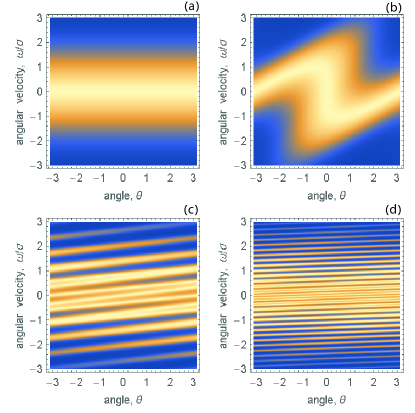
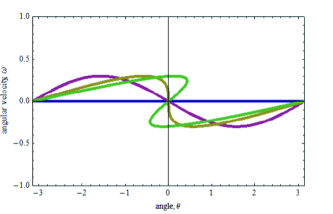
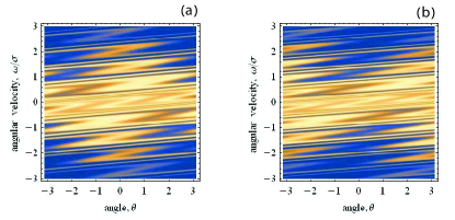
Assume now that at , the ensemble of rotors is subject to the second impulsive stimulus. The central filament in Fig. 2c (or Fig. 2d) which passes through the origin is quite analogous to the initial uniform distribution of rotors shown in Fig. 1 by the blue line, and it reacts similarly to the kick. With time, this filament forms the typical folded pattern leading to the transient orientation of the rotors in the filament. Other filaments experience the same transformation, with an important addition - for every angle , the emerging folded patterns start moving with respect to the central filament with the velocity difference , where is the filament number counted from the central one. As a result, the kick-induced patterns are generally shifted with respect to each other most of the time after the kick, which results in a more or less uniform total angular distribution considered as a function of only. If however the ensemble is observed with the delay after the kicking pulse, the kick-induced patterns of different filaments pile up on the top of each other in phase space (see Fig. 3a) manifesting increased density near and an echo in the orientation factor . Figure 3b demonstrates orientation along that happens a little bit later in the same time region (anti-orientation echo). This time evolution of the filaments reveals the mechanism leading to echoes in an ensemble of free rotors. The process involves two stages: (i) the first short kick compresses a sizable fraction of the ensemble in the vicinity of (orientation/alignment effect), and the subsequent free evolution results in filamentation of the phase space density, producing a series of parallel strips separated in angular velocity by the integer multiples of . (ii) The second impulsive stimulus applied at a delay after the first one induces the orientation/alignment dynamics in every filament, and all the emerging orientation/alignment patterns synchronously overlap near after another delay due to the above “quantization” of the angular velocities of the strips.
These qualitative arguments have a considerable predictive power. In particular, it is clear that the same mechanism should form the echo signals also at delays after the second pulse (higher order echoes). Moreover, it is expected that synchronization of the orientation/alignment patterns from non-neighboring strips at , … causes highly symmetric structures in the phase space, which may be associated with “fractional echoes”. These echoes are not seen in a mere orientation signal , but require higher order observables () to be measured as a function of time. Moreover, just looking at the phase space pattern at the moment of the main echo, Fig. 3a, one may expect that the echo is best manifested if the delay coincides with the time needed for achieving the maximal orientation in every strip. This means that for a given delay there should be an optimal intensity of the second kick, so that the echo signal is maximal at this intensity value.
The simple 2D model considered here (see Eq.(3)) allows for obtaining a fully analytical expression for the time-dependent mean value of where is an integer:
| (5) |
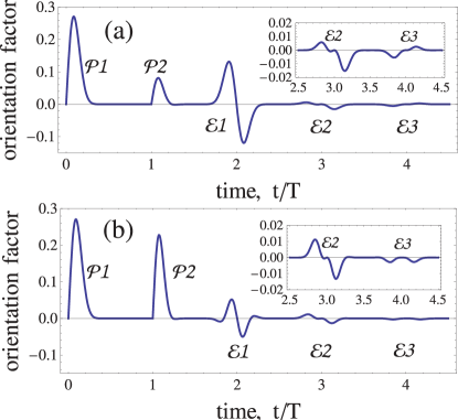
For this quantity is the orientation factor and the alignment factor of the ensemble, respectively. Equation (5) presents a sequence of signals localized in time near where is an integer. For , these are the above mentioned “fractional echoes”, while corresponds to the regular orientation echoes. Figure 4 presents calculated time-dependencies of the orientation factor for two values of the intensity of the second kick. It is clearly seen that the initial transient orientation shortly after the second pulse is followed by a series of echoes at and . In Figure 4a, the intensity of the second kick, was optimized to achieve the maximal amplitude of the main echo at . Although the second kick in Fig. 4a is three times weaker than that of Fig. 4b, it induces a considerably stronger echo, that even exceeds the initial response to the second kick. The peak and dip of the first echo in Fig. 4a correspond to the left and right panel of Fig. 3, respectively. As follows from Eq. (5), the amplitude of the echo is a decaying oscillatory function of the intensity of the second kick, after reaching the global maximum shown at Fig. 4a. This is related to the oscillatory behavior of the Bessel function in Eq. (5).
The same qualitative mechanism works in the case of the polarization-induced interaction (proportional to ) of the rotors with an external pulsed field, and it produces echoes in the ensemble averaged alignment signal, . An analytical expression for the alignment echo signals for 2D rotors is provided in the Supplementary Material SM , and it is quite similar to the Eq.(5). The visualization of the phase space transformations in the case of alignment is more involved due to the doubling of the angular modulation of the filaments, however the main qualitative results remain the same, including the non-monotonous dependence of the echo signals on the intensity of the second kick.
In what follows, we describe the first experimental observation of the rotational alignment echoes in laser-kicked CO2 molecules. The experimental setup had been used before Karras and is described in the Supplementary Material SM . The two linearly polarized pump pulses and are derived from an amplified Ti:Sapphire laser (1 kHz, 800 nm, 100 fs FWHM) and properly delayed before being focused inside a CO2 filled gas cell at a pressure of 0.2 bar. The alignment echoes are observed by time-resolved birefringence measurements Renard03 , where a delayed, weak probe pulse, linearly polarized at +45∘ relative to the pump pulses is linearly analyzed after passing through the cell by a polarizer set at -45∘ relative to the pump pulses. The birefringence signal measured on the detector can be written as Faucher2011
| (6) |
where is the alignment factor, and , , and , are the intensity of , , and the probe pulse, respectively.
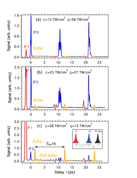
Figure 5 presents the pump-probe signals obtained for three different sets of pump intensities with a delay between and set to 1.6 ps. We measured the alignment signals till about one-half of the rotational revival time, of the CO2 molecule ( ps). Classical echo effects discussed in this paper happen within the time interval of about where the alignment dynamics is well described by the classical mechanics. To guide the eye, the alignment signals caused by the pulses and , and also their one-quarter and one-half revivals are colored in red and blue, respectively, whereas the echoes are highlighted with a yellow color.
For each intensity set, an echo is produced after at . Its amplitude depends on the intensities of both and . The maximum echo amplitude seen in Fig. 5c is achieved for the second pulse weaker than the first one, . In this case the echo is stronger than the initial response induced by the second pulse . These observations resemble the theoretical results shown in Fig. 4 considering the orientation process, and they may be understood using the similar qualitative arguments. The second echo produced at is also apparent in Fig. 5c. On the longer time scale, replicas of these echoes are observed near the one-quarter and half-revival regions. They appear due to the interplay between the classical echo effect and the phenomenon of fractional quantum revivals fr , and they are out of the scope of the present paper. These replicas are nicely reproduced in the fully quantum theoretical description of our experiments (to be published), and they have much in common with the revival echoes predicted in a collection of anharmonically confined cold atoms Fishman . Related transient signals were reported in Ref.chinese that studied alignment structures of N2O molecules excited by two strong femtosecond laser pulses. However the delay between the pulses in these experiments was chosen close to the quarter-revival time, far beyond the region where the classical echo effects of the present paper exist.
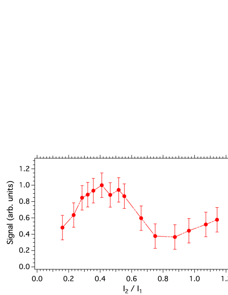
We also performed intensity-dependent measurements in order to reveal the non-monotonic behavior of the echo amplitude with respect to the intensity of the second pump pulse while keeping the first one () fixed. The results are summarized in Fig. 6 that clearly demonstrates the existence of an optimal intensity of the second kick, and the oscillatory dependence of the echo amplitude on this intensity. Both observations are consistent with the presented theoretical considerations.
Summarizing, we showed that a textbook classical system - a collection of randomly oriented free rotors with dispersed rotational velocities - exhibits multiple echoes of different kinds in its orientation/alignment dynamics when kicked by a pair of delayed pulses. We provided qualitative and quantitative analysis of the phenomenon using a simple model system, and performed the first experimental demonstration of the classical alignment echoes in a thermal gas of CO2 molecules excited by a pair of femtosecond laser pulses. The echoes were observed on a time scale much shorter than the quantum revival time, and their parameters were readily controllable by the intensity and delay of the excitation pulses. This makes the orientation/alignment echoes promising for exploring relaxation processes in high pressure gases and various liquids, including superfluid helium Helium , where quantum rotational responses are considerably suppressed. Studies on environmental influence on the orientation/alignment echoes are currently underway.
Acknowledgements.
This work was supported by the Conseil Régional de Bourgogne (PARI program), the CNRS, the Labex ACTION program (contract ANR-11-LABX-01-01), and the French National Research Agency (ANR) through the CoConicS program (Contract No. ANR-13-BS08-0013). This research was also supported by DFG (Project No. LE 2138/2-1) and Minerva Foundation. I.A. acknowledges kind hospitality and support from the Université Paris Est Créteil during a one week stay at LISA.References
- (1) E.L. Hahn, Phys. Rev. 80, 589 (1950).
- (2) H.Y. Carr, and E.M. Purcell, Phys. Rev. 94, 630 (1954).
- (3) R.M. Hill, and D.E. Kaplan, Phys. Rev. Lett. 14, 1062 (1965).
- (4) R.W. Gould, Phys. Lett. 19, 477 (1965).
- (5) R.W. Gould, T.M. O’Neil, J.H. Malmberg, Phys. Rev. Lett. 19, 219 (1967).
- (6) N.A. Kurnit, I.D. Abella, and S.K. Hartmann, Phys. Rev. Lett. 13, 567 (1964).
- (7) G.V. Stupakov, “Echo Effect In Hadron Colliders”, SSC Report SSCL-579, July 1992.
- (8) G.V. Stupakov and S. Kauffmann, ”Echo Effect in Accelerators”, SSC Report SSCL-587, September 1992.
- (9) L. K. Spentzouris, J. F. Ostiguy, and P. L. Colestock, Phys.Rev. Lett. 76, 620 (1996).
- (10) O. Bruning, T. Linnecon, F. Ruggio, W. Scandale, and E. Shaposhnikova, Nonlinear and Collective Phenomena in Beam Physics (AIP, New York, 1997), p. 155.
- (11) G. Stupakov, Phys. Rev. Lett. 102, 074801 (2009).
- (12) D. Xiang et al., Phys.Rev.Lett. 105, 114801 (2010).
- (13) Z.T. Zhao et al., Nature Photonics 6, 360 (2012).
- (14) G. Morigi, E. Solano, B.-G. Englert, and H. Walther, Phys. Rev. A 65, 040102 (2002).
- (15) T. Meunier, S. Gleyzes, P. Maioli, A. Auffeves, G. Nogues, M. Brune, J. M. Raimond, and S. Haroche, Phys. Rev. Lett. 94, 010401 (2005).
- (16) A. Bulatov, A. Kuklov, B.E. Vugmeister, and H. Rabitz, Phys. Rev. A 57, 3788 (1998).
- (17) F.B.J. Buchkremer, R. Dumke, H. Levsen, G. Birkl, and W. Ertmer, Phys. Rev. Lett. 85, 3121 (2000).
- (18) M.F. Andersen, A. Kaplan, and N. Davidson, Phys. Rev. Lett. 90, 023001 (2003).
- (19) M. Herrera, T.M. Antonsen, E. Ott, and S. Fishman, Phys. Rev. A 86, 023613 (2012).
- (20) R.W. Boyd, Nonlinear Optics (Academic Press, Boston, 1992).
- (21) B. Friedrich and D. Herschbach, Phys. Rev. Lett. 74, 4623 (1995); J. Phys. Chem. 99, 15 686 (1995).
- (22) H. Stapelfeldt and T. Seideman, Rev. Mod. Phys. 75, 543 (2003)
- (23) Y. Ohshima and H. Hasegawa, Int. Rev.Phys. Chem. 29, 619 (2010).
- (24) S. Fleischer, Y. Khodorkovsky, E. Gershnabel, Y. Prior, and I. Sh. Averbukh, Isr. J. Chem. 52, 414 (2012).
- (25) M. Lemeshko, R. V. Krems, J. M. Doyle, S. Kais, Mol. Phys. 111, 1648 (2013).
- (26) S. Pabst, The European Physical Journal Special Topics, 221, 1-71 (2013).
- (27) A.J. Lichtenberg, M.A. Lieberman, Regular and chaotic dynamics, Springer, Berlin (1992).
- (28) I. Sh. Averbukh and R. Arvieu, Phys. Rev. Lett. 87, 163601 (2001).
- (29) A.J. Lichtenberg, Phase-space dynamics of particles, Wiley, New York, 1969.
- (30) D. Lynden-Bell, Mon. Not. R. Astr. Soc. 136, 101 (1967).
- (31) see the attached Supplemental Material for the analytical expression for the alignment echoes in 2D model with the polarization-induced interaction, and for the details of the experimental setup.
- (32) G. Karras, E. Hertz, F. Billard, B. Lavorel, J.-M. Hartmann, and O. Faucher, Phys. Rev. A 89 063411 (2014).
- (33) V. Renard, M. Renard, S. Guérin, Y. T. Pashayan, B. Lavorel, O. Faucher, and H. R. Jauslin, Phys. Rev. Lett. 90, 153601 (2003).
- (34) O. Faucher, B. Lavorel, E. Hertz, and F. Chaussard, in it Progress in Ultrafast Intense Laser Science, vol. VII (Springer, 2011), vol. 100 of Springer Series in Chemical Physics, pp. 79-108.
- (35) I.Sh. Averbukh and N.F. Perelman, Phys. Lett. A 139, 449 (1989).
- (36) H. Jiang, C. Wu, H. Zhang, H. Jiang, H. Yang and Q. Gong, Opt. Express 18, 8990 (2010).
- (37) D. Pentlehner, J. H. Nielsen, A. Slenczka, K. Mølmer, and H. Stapelfeldt, Phys. Rev. Lett. 110, 093002 (2013).
Supplementary material
Alignment echoes
Here we briefly summarize results for alignment echo in the systems that interact with electromagnetic field via the induced polarization (2). The kick transformation describing the angular velocity, and angle of a rotor at time after the first kick is given by the map (3), in which is replaced by . By applying this transformation twice, we obtain the angular position of the rotor at time after the second kick that was applied at :
| (S-1) |
Using this expression, we calculate the time-dependent alignment factor
| (S-2) |
With the help of the well known formula
| (S-3) |
we expand in series of Bessel functions , combine together all the terms proportional to in the exponent, and perform the Gaussian integration. This yelds
| (S-4) |
We perform the remaining integration in (S-4) with the help of the inverse Fourier transform of Eq. (S-3), shift the summation index by 1, and neglect terms with the negative index (they are exponentially small if ):
| (S-5) |
Expression (S-5) describes alignment echoes happening at (). The term for describes the transient response just after the second pulse. The alignment factor (S-5) is very similar (up to the overall shift by 1/2, and rescaling the parameters) to the analytical expression for the orientation factor (5). Therefore, all the qualitative properties of the echo signals discussed before for the orientation process, are applicable to the alignment process as well.
Experimental setup
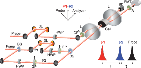
A schematic representation of the experimental apparatus is presented in Fig. 7. The laser source is a Ti:Sapphire based, chirped-pulse amplified system delivering pulses centered at 800 nm with duration of 100 fs. The output pulses have a maximum energy of 3.5 mJ at 1 kHz repetition rate. A Mach-Zehnder interferometer generates two pump pulses and with a relative delay adjustable through a computer controlled translation stage equipped with a corner cube reflector. These two pulses are linearly polarized in the same direction and focused inside a static cell using a plano-convex lens. The cell is filled with CO2 molecules at room temperature under a pressure of 0.2 bar. The alignment echoes are observed by time-resolved birefringence measurements, a non-invasive method so far successfully applied to the detection of field-free molecular alignment Renard03 . A probe pulse is produced by inserting a beam splitter in the beam path just after the exit of the laser source. It is delayed using a second motorized translational stage, its energy is about two orders of magnitude lower than those of the pump pulses and its polarization is linear and set to +45∘ with respect to the polarization of the pump pulses. The transient molecular alignment induced by the pump pulses is revealed by the depolarization of the probe field recorded as a function of the delay between and the probe pulse. The depolarized field component is selected by a linear analyzer located after the cell and set at with respect to the polarization of the pump pulses. The birefringence signal measured on the detector can be written as shown in Eq.(6) (see Faucher2011 ). Finally, control over the energy of all beams is achieved using the combination of zero-order half wave-plates and Glan polarizers.