Spin-orbit coupled repulsive Fermi atoms in a one-dimensional optical lattice
Abstract
Motivated by recent experimental development, we investigate spin-orbit coupled repulsive Fermi atoms in a one-dimensional optical lattice. Using the density-matrix renormalization group method, we calculate momentum distribution function, gap, and spin-correlation function to reveal rich ground-state properties. We find that spin-orbit coupling (SOC) can generate unconventional momentum distribution, which depends crucially on the filling. We call the corresponding phase with zero gap the SOC-induced metallic phase. We also show that SOC can drive the system from the antiferromagnetic to ferromagnetic Mott insulators with spin rotating. As a result, a second-order quantum phase transition between the spin-rotating ferromagnetic Mott insulator and the SOC-induced metallic phase is predicted at the strong SOC. Here the spin rotating means that the spin orientations of the nearest-neighbor sites are not parallel or antiparallel, i.e., they have an intersection angle . Finally, we show that the momentum , at which peak of the spin-structure factor appears, can also be affected dramatically by SOC. The analytical expression of this momentum with respect to the SOC strength is also derived. It suggests that the predicted spin-rotating ferromagnetic () and antiferromagnetic () correlations can be detected experimentally by measuring the SOC-dependent spin-structure factor via the time-of-flight imaging.
pacs:
03.75.Ss, 67.85.Lm,
Keywords: Repulsive Fermi atoms, Spin-orbit coupling, Optical lattice
1 Introduction
Ultracold Fermi atoms in optical lattices have attracted considerable interest both experimentally [1, 2, 3, 4, 5, 6, 7, 8, 9, 10, 11, 12, 13, 14, 15, 16] and theoretically [17, 18, 19, 20, 21, 22, 23, 24, 25, 26, 27, 28, 29, 30, 31, 32, 33, 34, 35, 36, 37, 38, 39, 40, 41], because these setups are powerful platforms to simulate rich physics of strongly-correlated materials [42, 43]. One of advantages of this system is that the spatial geometry of optical lattices can be well controlled. Especially, using a strong harmonic transverse confinement, one-dimensional (1D) optical lattices have been achieved experimentally [2, 9]. On the other hand, the relative parameters have high controllability, and moreover, can reach the regimes that cannot be accessible in the conventional condensed-matter physics. For example, the two-body interaction between Fermi atoms can be tuned by a magnetic-field-dependent Feshbach resonant technique [44], and thus ranges from the positive (repulsive) to the negative (attractive). For the on-site repulsive interaction, a well-known second-order quantum phase transition between an antiferromagnetic Mott insulator and a metallic phase can emerge [45].
Another important breakthrough in recent experiments of ultracold Fermi atoms is to successfully create a synthetic spin-orbit coupling (SOC), with equal Rashba and Dresselhaus strengths, by a pair of counter-propagating Raman lasers [46, 47, 48, 49]. Indeed, SOC describes interaction between the spin and orbit degrees of freedom of a particle. In contrast to the typical property of solid state materials that the intrinsic SOC strength is generally smaller than the Fermi velocity of electrons, this synthetic SOC strength realized can reach the same order as (or even larger than) the Fermi velocity of atoms, and moreover, can also be tuned in a wide range [50, 51]. Recent theory has revealed that SOC can generate exotic superfluids, including topological Bardeen-Cooper-Schrieffer [52, 53, 54, 55, 56, 57, 58, 59] and topological Fulde-Ferrell-Larkin-Ovchinnikov [60, 61, 62] phases, for the attractive Fermi atoms. The fundamental picture for achieving these nontrivial topological superfluids is that SOC, Zeeman field, and -wave interaction can induce triplet -wave pairing [63, 64, 65]. In parallel with the attractive case, it is natural to ask what novel physics can occur in the repulsive Fermi atoms driven by the synthetic SOC [66, 67, 68].
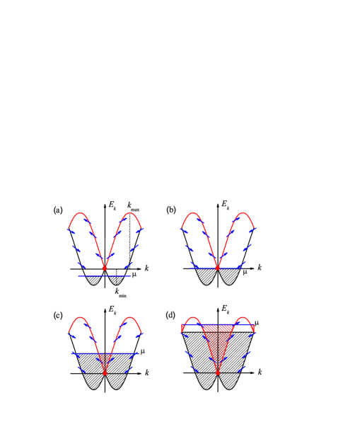
Inspired by the above experimental developments and theoretical considerations, here we investigate spin-orbit coupled repulsive Fermi atoms in a 1D optical lattice. Recently, spin-orbit coupled Bose-Einstein condensates in the 1D optical lattice has been prepared experimentally [69]. Using a similar technique, the system considered could also be achieved in the near future. Physically, the spin-orbit coupled Fermi atoms in the optical lattices have two characteristics. One is that SOC can make Fermi atoms hop between the nearest-neighbor sites with spin flipping; see the Hamiltonian (6) in the following. Moreover, it has a strong competition with the on-site repulsive interaction, and especially, with the conventional spin-independent hopping; see the Hamiltonian (4) in the following. The other is that in the presence of SOC, for different chemical potentials, the fillings are quite different; see Fig. 1.
Notice that in 1D quantum fluctuation becomes significant, and the mean-field results are, in principle, unreliable [70]. Here we capture the required ground-state properties, including momentum distribution and spin-correlation, by using the density-matrix renormalization group (DMRG) method [71, 72], which is a powerful numerical method to study lower-dimensional strong-correlated systems [73]. The main results are given as follows. Section is devoted to introducing our proposal and deriving a 1D Fermi-Hubbard model with the synthetic SOC. Section is devoted to addressing the generalized results without the on-site repulsive interaction. In this section, the unconventional momentum distribution, which depends crucially on the filling, are found. We call the corresponding phase the SOC-induced metallic phase. Section is devoted to discussing the results in the presence of the on-site repulsive interaction. By means of the spin-correlation function, we find that SOC can drive the system from a spin-rotating antiferromagnetic Mott insulator to a spin-rotating ferromagnetic Mott insulator. As a result, a second-order quantum phase transition between the spin-rotating ferromagnetic Mott insulator and the SOC-induced metallic phase is predicted at the strong SOC. Here the spin rotating means that the spin orientations of the nearest-neighbor sites are not parallel or antiparallel, i.e., they have an intersection angle (see Fig. 8 in the following). In the spin-rotating antiferromagnetic Mott insulator, , and the quasi-long-range spin correlation decays as a power law and changes the sign with a period , whereas for the spin-rotating ferromagnetic Mott insulator, , and the quasi-long-range spin correlation also decays as a power law but with the period . Finally, we show that the momentum , at which peak of the spin-structure factor appears, can also be affected dramatically by SOC. The analytical expression of this momentum with respect to the SOC strength is also derived. It suggests that the predicted spin-rotating ferromagnetic () and antiferromagnetic () correlations can be detected experimentally by measuring the SOC-dependent spin-structure factor via the time-of-flight imaging [74]. The discussions and conclusions are given in section .
2 Model and Hamiltonian
2.1 Proposed experimental setup
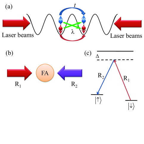
Figure 2 shows our proposal that repulsive Fermi atoms in a 1D optical lattice are driven by a pair of counter-propagating Raman lasers. For the specific experiments, 3D optical lattice is first prepared by the interference of three pairs of counter-propagating laser beams [42, 43]. The corresponding periodic potential can be written as , where is the lattice depth, is the wave vector, and is wavelength. By further using a strong harmonic transverse confinement in the 3D optical lattice, i.e., the 2D harmonic potential frequency is far larger than the trapping frequency along the weakly-confining axis, the required 1D optical lattice can be generated [2, 9]; see Fig. 2(a). In such case, the two-body interaction between Fermi atoms is described effectively by [75]
| (1) |
with the 1D -wave scattering length
| (2) |
where , , is the 3D -wave scattering length, and is the atomic mass. In addition, a pair of counter-propagating Raman lasers shown in Fig. 2(b) are used to create the required 1D synthetic SOC, with equal Rashba and Dresselhaus strengths [76]. In this method, the corresponding two spin states are chosen as and for 40K system [46], or and for 6Li system [49]; see Fig. 2(c).
2.2 Hamiltonian
The total dynamics illustrated by Fig. 2 is governed by the following 1D Fermi-Hubbard model with the synthetic SOC [71, 72]:
| (3) |
with
| (4) |
| (5) |
and
| (6) |
where and are the creation and annihilation operators, with spin , at lattice site , is the number operator, is the spin-independent hopping magnitude, is the on-site repulsive interaction strength, and is the SOC strength. Based on above proposal experimental setups, the relative parameters can be tuned independently. For example, the hopping magnitude can be controlled by the intensities of lasers [42, 43], the 1D on-site repulsive interaction strength can be tuned by Feshbach resonance [44], and the SOC strength can be driven through a fast and coherent modulation of Raman lasers [50, 51]. As a consequence, for a proper optical lattice, the SOC strength has the same order of the hopping magnitude [77].
2.3 Momentum distribution and spin correlation
In terms of the SOC-induced properties (see Introduction), here we mainly focus on momentum distribution and spin correlation, which can be measured experimentally by the time-of-flight imaging [4, 15, 46, 74]. The momentum distribution functions for spin-up and spin-down atoms are written respectively as [78]
| (7) |
| (8) |
For the Hamiltonian (3), the spin-up and spin-down atoms are equal. It means that is the same as , and thus we only consider in the following discussions. The spin-correlation function is defined as [74, 78, 79]
| (9) |
where is a distance between different sites and . The corresponding spin-structure factor is given by [74, 78, 79]
| (10) |
Since the spin-structure factor has the sum extending over all lattice sites and , it reflects spin correlation globally, and is thus used experimentally to detect the magnetic order [74].
3 Without on-site repulsive interaction
In order to better understand the fundamental physics induced by SOC, we first consider a simple case without the on-site repulsive interaction (), in which the Hamiltonian (3) reduces to , i.e.,
| (11) |
In experiments, the 1D noninteracting Fermi atoms can be realized by tuning the 3D -wave scattering length to its zero crossing. In such case, the 1D -wave scattering length , and the 1D effective two-body interaction then becomes zero [6, 7, 43]; see Eqs. (1) and (2).
3.1 Momentum distribution function
In the absence of SOC (), the system have three known features. Firstly, the energy bands of the Hamiltonian are degenerate, and the system is located at the metallic phase. Secondly, all Fermi atoms occupy the degenerate energy bands from , where is the minimum of the energy bands. Moreover, there are two degenerate Fermi surfaces at the Fermi momentum [82], with filling factor , where is the total atomic number. At last, the chemical potential cuts the degenerate energy bands, with the Fermi momenta . As a result, the momentum distribution function has a plateau of , with sharp edges at ; see the black solid curve of Fig. 3(a). In the large- limit, this plateau of disappears and two plateaus of emerge, as expected. For the different chemical potentials, the fillings are similar, and the momentum distributions are thus similar; see the black solid curves of Figs. 3(b) and 3(c).
In the presence of SOC (), the results are very interesting. In this case, the energy bands governed by the Hamiltonian split into two nondegenerate subbands, whose minima and maxima are given respectively by
| (12) |
| (13) |
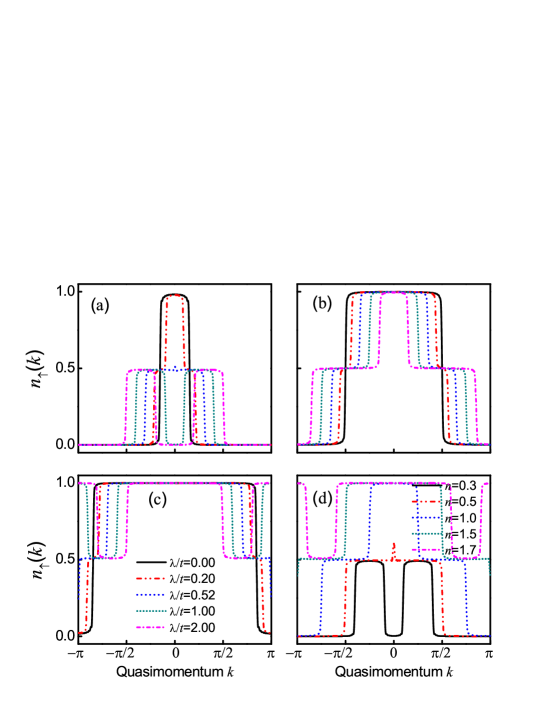
It is easy to find that . For , , as expected. In the presence of SOC (), there are generally four Fermi points, when the chemical potential cuts two nondegenerate subbands. If the chemical potential is identical to the critical chemical potential that just cuts the contact point [see the blue curve in Fig. 1(b)], three Fermi points can emerge. More importantly, for the different chemical potentials, the fillings are quite different; see Fig. 1. These different fillings affect dramatically on momentum distributions. As examples, we plot, in Fig. 3, the momentum distribution functions for the different SOC strengths , when the filling factors are chosen as (a) , (b) , and (c) .
It can be seen from Fig. 3(a) that for a smaller filling, any SOC leads to a new momentum distribution, in which the corresponding function has two plateaus of , apart from the conventional plateau of . The physical explanation is given as follows. When the SOC strength is not strong enough (see, for example, ), , and thus both the lower and upper subbands are partly occupied; see Fig. 1(c). The occupation in the upper subband determines the plateau of , while the occupation in the lower subband governs two plateaus of . With the increasing of the SOC strength , i.e., the chemical potential decreases [83, 84], the occupation in the upper subband becomes less, and thus the wide of the plateau of becomes narrower. In particular, when , the plateau of disappears, since in this case , and thus no occupation in the upper subband can be found. If further increasing the SOC strength , i.e., , a plateau of emerges around (not in the large- limit). This is because there is no occupation around when ; see Fig. 1(a). For the half filling (), we find that the momentum distribution function usually has two plateaus of and [see Fig. 3(b)], because and both the lower and upper subbands are partly occupied. For a larger filling factor (see, for example, ), the momentum distribution function has two plateaus of and when ; see Fig. 3(c). In this case, and the lower subband is totally occupied with a part occupation in the upper subband; see Fig. 1(d). This case cannot occur in the smaller filling factors. We call the corresponding phase, with above unconventional momentum distributions, the SOC-induced metallic phase. Finally, in order to see clearly the above evolution of momentum distribution with respect to the filling factor, we plot the momentum distribution functions for the different filling factors in Fig. 3(d).
It should be noticed that in the case with a Zeeman field, but without SOC, the chemical potential cutting the Zeeman-split bands also results in more than two Fermi points. But the momentum distribution function is quite different from that induced by SOC. In such case, the momentum distribution function only has the plateaus of . Moreover, for the different chemical potentials, the fillings are similar, and thus the momentum distribution functions are also similar. However, in our considered case with SOC, but without the Zeeman field, the momentum distribution function has the new plateaus of , apart from , and moreover, the filling-dependent unconventional momentum distributions emerge.
3.2 Spin-correlation function and spin-structure factor
Since SOC can make Fermi atoms hop between the nearest-neighbor sites, with spin flipping [see Fig. 2(a) and the Hamiltonian (6)], it has a competition with the conventional spin-independent hopping. This competition has a strong effect on spin distributions of different sites. To see this clearly, we consider the spin-correlation function in Eq. (9).
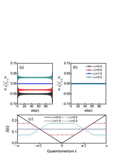
In Figs. 4(a) and 4(b), we plot the spin correlations between the nearest-neighbor sites, i.e., , and the next-nearest-neighbor sites, i.e., , respectively. These two subfigures show clearly that in the absence of SOC (), and , which means that this short-range spin correlation is negative. In the presence of SOC (), the spin correlation is still short range. Interestingly, with the increasing of the SOC strength , the spin correlation varies from the negative to the positive at the critical point . The physical reason will be illustrated in the following section.
In Fig. 4(c), we plot the spin-structure factors for the different SOC strengths at the half filling (). In the absence of SOC (), the spin-structure factor evolves as a straight line from to , and has a cusp at [78]. For a finite SOC strength , the spin-structure factor is and . When , the spin-structure factor becomes a constant , since in this case no short-range spin correlation can be found. When , the spin-structure factor is similar to the case of .
4 With on-site repulsive interaction
We now consider the case with the on-site repulsive interaction (). In the absence of SOC (), it has been demonstrated exactly that for the 1D homogeneous Fermi-Hubbard model at the half filling (), the metallic phase occurs at . For , the system is always located at the antiferromagnetic Mott insulator [45], in which the spin orientations of the nearest-neighbor sites are antiparallel [78]. It means that a second-order quantum phase transition between the metallic phase and the antiferromagnetic Mott insulator emerges at . In the following, we will show that SOC can drive the system from the antiferromagnetic to ferromagnetic Mott insulators with spin rotating (i.e., the spin orientations of the nearest-neighbor sites are not parallel or antiparallel), and predict a second-order quantum phase transition between the spin-rotating ferromagnetic Mott insulator and the SOC-induced metallic phase at the half filling ().

4.1 Momentum distribution function and gap
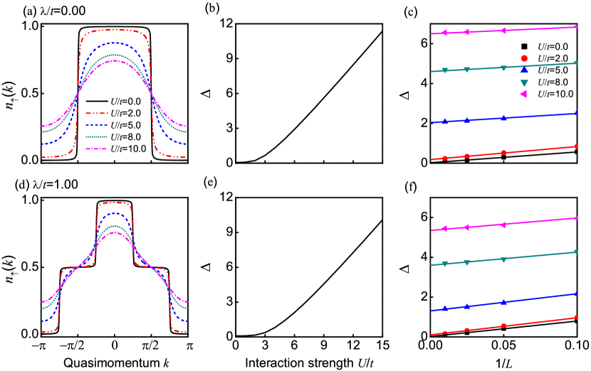
Figures 5(a) and 5(d) show the momentum distribution functions for the different SOC strengths at the half filling (). In the absence of SOC () and the on-site repulsive interaction strength (), the momentum distribution function has two sharp edges at ; see the black solid curve in Fig. 5(a). When increasing the on-site repulsive interaction strength , the momentum distribution functions become smoother and all sharp edges disappear. In order to see the relevant physics more clearly, we introduce the gap [45]
| (14) |
where and , with the ground-state energy . This gap reflects the difference between the energy required to add () and remove () a Fermi atom from the ground state. In the thermodynamic limit (), it has been demonstrated rigorously that for and for . Moreover, corresponds to the metallic phase and corresponds to the Mott insulator [45]. In our numerical results, due to finite-size effects, the gap is not absolute zero when ; see Fig. 5(b). However, this result can be extrapolated to the thermodynamic limit by a finite-size-scaling analysis [85, 86]. As shown in Fig. 5(c), we find for and for in the thermodynamical limit. Therefore, here we call the phase, in which has sharp edges at and (thermodynamical limit), the metallic phase, whereas the phase, in which become smoother, all sharp edges disappear, and (thermodynamical limit), is referred as the Mott insulator [45]. Since in this Mott insulator the spin orientations of the nearest-neighbor sites are antiparallel, the phase is finally called the antiferromagnetic Mott insulator (see also the following discussions).
In the presence of SOC (see, for example, ), the momentum distribution function is unconventional and (thermodynamical limit), when ; see the black solid curve in Figs. 5(d)-5(f). It implies that the system is located at the SOC-induced metallic phase. When increasing the on-site repulsive interaction strength , these momentum distribution functions also become smoother, all sharp edges also disappear, and (thermodynamical limit), i.e., the system enters into the Mott insulator. However, as will be shown in the next subsection, these Mott insulators, without SOC or with SOC, are quite different. Without SOC, the Mott insulator is antiferromagnetic, whereas it becomes spin-rotating antiferromagnetic if , and spin-rotating ferromagnetic if .
In Figs. 6(a)-6(c), we plot the momentum distribution functions and the gap for the different filling factors , when and . If , all sharp edges (Fermi points) in the momentum distribution functions still exist and the zero gap, (thermodynamical limit), remains. These indicate that the system is always located at the SOC-induced metallic phase for any on-site repulsive interaction strength . However, at the half filling (), the momentum distribution function becomes smoother and (thermodynamical limit) for any on-site repulsive interaction strength . These mean that these Mott insulators only occur at the half filling (), which is similar to the result without SOC [45].

4.2 Spin-correlation function and spin-structure factor
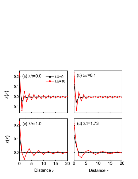
In Figs. 7(a)-7(d), we plot the spin-correlation functions for the different SOC strengths . These figures show clearly that in the presence of the on-site repulsive interaction (), quasi-long-range spin correlation appears, i.e., . This is contrast to the result without the on-site repulsive interaction, in which only the short-range spin correlation emerges; see Figs. 4(a) and 4(b). When increasing the SOC strength , the spin-correlation functions between the nearest-neighbor sites vary from the negative to the positive. In order to see this physics more clearly, we plot, in Figs. 8(a)-8(d), spin distributions of each sites, i.e., , where and with the ground-state wavefunction , for the different SOC strengths . We define an intersection angle between the different spin orientations of the nearest-neighbor sites.
In the absence of SOC (), the spin orientations of the nearest-neighbor sites are antiparallel and ; see Figs. 8(a). Moreover, the spin-correlation function if is odd, while if is even; see Fig. 7(a). These mean that the corresponding spin-spin interactions of the nearest-neighbor sites are antiferromagnetic. In addition, the spin-correlation function decays as a power law and changes the sign with a period [18]; see also Fig. 7(a). This phase is usually called the antiferromagnetic Mott insulator. In the presence of SOC (see, for example, ), the spin orientations of the nearest-neighbor sites are not antiparallel (i.e., the spins are rotating) and ; see Figs. 8(b). Since in this case the traditional spin-independent hopping still plays a dominate role, the quasi-long-range antiferromagnetic spin correlation remains, but with a period ; see Fig. 7(b). Thus, we call the corresponding phase the spin-rotating antiferromagnetic Mott insulator. When , the spin orientations of the nearest-neighbor sites are vertical and ; see Figs. 8(c). Moreover, with a period , which means that no spin correlation between the nearest-neighbor sites can be found; see Fig. 7(c). At the strong SOC (), the SOC-induced hopping plays a dominate role. In this case, the spin orientations of the nearest-neighbor sites tend to parallel and ; see Figs. 8(d). Moreover, , which indicates that the spin-spin interactions of the nearest-neighbors sites become ferromagnetic. In addition, the quasi-long-range spin-correlation function also decays as a power law, but changes the sign with a period ; see Fig. 7(d). We call the corresponding phase the spin-rotating ferromagnetic Mott insulator. From above discussions, we argue that SOC can drive the system from the spin-rotating antiferromagnetic Mott insulator to the spin-rotating ferromagnetic Mott insulator.
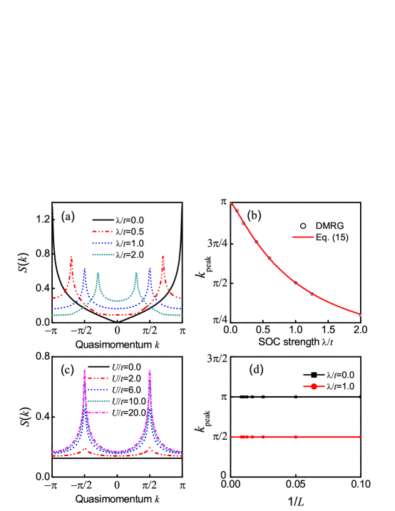
Figure 9(a) shows the experimentally-measurable spin-structure factors for the different SOC strengths at the half filling (). In the absence of SOC (), the system has the antiferromagnetic order [78, 87], and the spin-structure factor has a peak at the momentum , as expected. When increasing the SOC strength , the peak still exists and varies as
| (15) |
It is easy to find from Eq. (15) that when , ; see Fig. 9(b). When , the system has the spin-rotating antiferromagnetic Mott insulator with . When , the system has the spin-rotating ferromagnetic Mott insulator with . Since the antiferromagnetic order has been detected experimentally by measuring via the time-of-flight imaging [74], these spin-rotating ferromagnetic and antiferromagnetic orders can also be detected by the same method. For a fixed SOC strength , when increasing the on-site repulsive interaction strength , the momentum remains unchanged, while the magnitudes of peaks increase; see Fig. 9(c). In Fig. 9(d), we present a finite-size-scaling analysis of the momentum . This figure shows that the momentum remains unchanged when increasing the lattice length .
4.3 Phase diagram
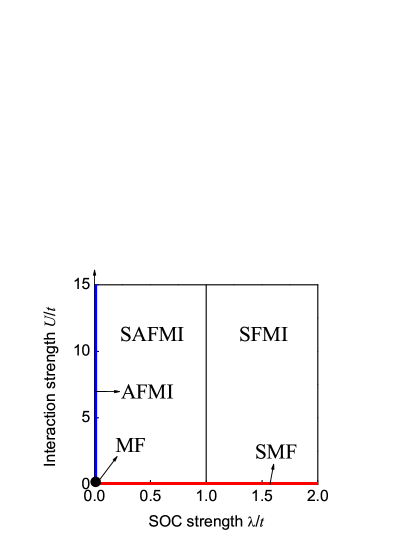
Based on the predicted properties of the momentum distribution, the gap, and the spin correlation, we find that the homogeneous Hamiltonian (3) has five phases, including the metallic phase, the SOC-induced metallic phase, the antiferromagnetic Mott insulator, the spin-rotating antiferromagnetic Mott insulator, and the spin-rotating ferromagnetic Mott insulator, at the half filling (). In the metallic phase, the system has conventional momentum distribution with the gap (thermodynamical limit), while it becomes filling-dependent unconventional momentum distribution but with the same zero gap (thermodynamical limit) in the SOC-induced metallic phase. In the antiferromagnetic, spin-rotating antiferromagnetic, and spin-rotating ferromagnetic Mott insulators, the system has a nonzero gap (thermodynamical limit) and the quasi-long-range spin correlation decaying as a power law. However, in the antiferromagnetic Mott insulator, , , and . In the spin-rotating antiferromagnetic Mott insulator, , , and . Whereas in the spin-rotating ferromagnetic Mott insulator, , , and .
In Fig. 10, we give a schematic phase diagram as a function of the SOC strength and the on-site repulsive interaction strength . In this figure, the Mott insulator and the metallic phase are separated by the gap (thermodynamical limit) [45]. The metallic phase and the SOC-induced metallic phase are separated by the momentum distribution function . The antiferromagnetic Mott insulator and the spin-rotating antiferromagnetic Mott insulator are separated by , , and . The spin-rotating antiferromagnetic Mott insulator and the spin-rotating ferromagnetic Mott insulator are separated by , , and .
We also find that the transitions between the metallic phase and the antiferromagnetic Mott insulator, between the SOC-induced metallic phase and the spin-rotating antiferromagnetic Mott insulator, and between the SOC-induced metallic phase and the spin-rotating ferromagnetic Mott insulator are of second order, because the second-order derivative of the ground-state energy is discontinuous at the critical points. For the other transitions, the ground-state energy and its derivative vary smoothly. It means that no phase transition can be found, although for the different phases, the momentum distribution and the spin correlation are different.
5 Discussions and conclusions
Before ending up this paper, we make one remark. In the real experiment, the Zeeman field usually exists. When the Zeeman field is considered, an extra Hamiltonian
| (16) |
should be added in the Hamiltonian (3). This Zeeman field can lead to spin flipping in the same site. Moreover, it has a strong competition with SOC, which makes Fermi atoms hop between the nearest-neighbor sites with spin flipping, and the conventional spin-independent hopping between the nearest-neighbor sites. As a consequence, rich magnetic properties can emerge. The deep understanding of relevant behavior is very complicated (we need introduce more physical quantities), but interesting. We leave this important problem for further investigation.
In summary, we have investigated spin-orbit coupled repulsive Fermi atoms in a 1D optical lattice by the DMRG method. We have found that SOC can generate the filling-dependent unconventional momentum distribution, whose corresponding phase is called the SOC-induced metallic phase, and drive the system from the spin-rotating antiferromagnetic Mott insulator to the spin-rotating ferromagnetic Mott insulator. We have predicted a second-order quantum phase transition between the spin-rotating ferromagnetic Mott insulator and the SOC-induced metallic phase at the strong SOC. Finally, we have also shown that the momentum, at which peak of the spin-structure factor appears, can be affected dramatically by SOC. The analytical expression of this momentum with respect to the SOC strength has also been derived. Attributed to the recent experimental realization of the spin-orbit coupled Bose-Einstein condensates in the 1D optical lattice [69], we expect that our predictions could be observed in the near future. In particular, the spin-rotating ferromagnetic and antiferromagnetic correlations can be detected by measuring the SOC-dependent spin-structure factor via the time-of-flight imaging [74].
References
References
- [1] Köhl M, Moritz H, Sötferle T, Günter K and Esslinger T 2005 Phys. Rev. Lett. 94 080403
- [2] Moritz H, Sötferle T, Günter K, Köhl M and Esslinger T 2005 Phys. Rev. Lett. 94 210401
- [3] Chin J K, Miller D E, Liu Y, Stan C, Setiawan W, Sanner C, Xu K and Ketterle W 2006 Nature 443 961
- [4] Rom T, Best Th, Oosten D van, Schneider U, Fölling S, Paredes B and Bloch I 2006 Nature 444 733
- [5] Stöferle T, Moritz H, Günter K, Köhl M and Esslinger T 2006 Phys. Rev. Lett. 96 030401
- [6] Strohmaier N, Takasu Y, Günter K, Jördens R, Köhl M, Moritz H and Esslinger T 2007 Phys. Rev. Lett. 99 220601
- [7] Jördens R, Strohmaier N, Günter K, Moritz H and Esslinger T 2008 Nature 455 204
- [8] Schneider U, Hackermüller L, Will S, Best T, Bloch I, Costi T A, Helmes R W, Rasch D and Rosch A 2008 Science 322 1520
- [9] Liao Y-a, Rittner A S C, Paprotta T, Li W, Partridge G B, Hulet R G, Baur S K and Mueller E J 2010 Nature 467 567
- [10] Strohmaier N, Greif D, Jördens R, Tarruell L, Moritz H, Esslinger T, Sensarma R, Pekker D, Altman E and Demler E 2010 Phys. Rev. Lett. 104 080401
- [11] Tarruell L, Greif D, Uehlinger T, Jotzu G and Esslinger T 2012 Nature 483 302
- [12] Krauser J S, Heinze J, Fläschner N, Götze S, Jürgensen O, Lühmann D, Becker C and Sengstock K 2012 Nat. Phys. 8 813
- [13] Greif D, Uehlinger T, Jotzu G, Tarruell L and Esslinger T 2013 Science 340 1307
- [14] Heinze J, Krauser J S, Fläschner N, Hundt B, Götze S, Itin A, Mathey L, Sengstock K and Becker C 2013 Phys. Rev. Lett. 110 085302
- [15] Pagano G, Mancini M, Cappellini G, Lombardi P, Schäfer F, Hu H, Liu X-J, Catani J, Sias C, Inguscio M and Fallani L 2014 Nat. Phys. 10 198
- [16] Duarte P M, Hart R A, Yang T-L, Liu X-X, Paiva T, Khatami E, Scalettar R T, Trivedi N and Hulet R G 2015 Phys. Rev. Lett. 114 070403
- [17] Rigol M, Muramatsu A, Batrouni G G and Scalettar R T 2003 Phys. Rev. Lett. 91 130403
- [18] Rigol M and Muramatsu A 2004 Phys. Rev A. 69 053612
- [19] Liu X-J, Drummond P D and Hu H 2005 Phys. Rev. Lett. 94 136406
- [20] Iskin M and Sá de Melo C A R 2005 Phys. Rev. B 72 224513
- [21] Iskin M 2013 Phys. Rev. A 88 053606
- [22] Zhao E and Paramekanti A 2006 Phys. Rev. Lett. 97 230404
- [23] Gao X, Rizzi M, Polini M, Fazio R, Tosi M, Campo V and Capelle K 2007 Phys. Rev. Lett. 98 030404
- [24] Mathey L, Tsai S-W and Castro Neto A H 2007 Phys. Rev. B 75 174516
- [25] Moreo A and Scalapino D 2007 Phys. Rev. Lett. 98 216402
- [26] Gu S-J, Fan R and Lin H-Q 2007 Phys. Rev. B 76 125107
- [27] Karim Pour F, Rigol M, Wessel S and Muramatsu A 2007 Phys. Rev. B 75 161104
- [28] Andersen B and Bruun G 2007 Phys. Rev. A 76 041602
- [29] Bakhtiari M R, Leskinen M J and Törmä P 2008 Phys. Rev. Lett. 101 120404
- [30] Tezuka M and Ueda M 2008 Phys. Rev. Lett. 100 110403
- [31] Tezuka M and Ueda M 2010 New J. Phys. 12 055029
- [32] Machida M, Okumura M, Yamada S, Deguchi T, Ohashi Y and Matsumoto H 2008 Phys. Rev. B 78 235117
- [33] Wu K and Zhai H 2008 Phys. Rev. B 77 174431
- [34] Chen Y, Wang Z, Zhang F and Ting C 2009 Phys. Rev. B 79 054512
- [35] Chen A-H and Gao X 2010 Phys. Rev. A 81 013628
- [36] Sun K, Vincent Liu W, Hemmerich A and Das Sarma S 2011 Nat. Phys. 8 67
- [37] Yamamoto A, Yamada S, Okumura M and Machida M 2011 Phys. Rev. A 84 043642
- [38] Kobayashi K, Okumura M, Ota Y, Yamada S and Machida M 2012 Phys. Rev. Lett. 109 235302
- [39] Volčko D and Quader K F 2012 Phys. Rev. Lett. 109 235303
- [40] Shen Z, Radzihovsky L and Gurarie V 2012 Phys. Rev. Lett. 109 245302
- [41] Wang S-T, Deng D-L and Duan L-M 2014 Phys. Rev. Lett. 113 033002
- [42] Lewenstein M, Sanpera A, Ahufinger V, Damski B, Sen(De) A and Sen U 2007 Adv. Phys. 56 243
- [43] Esslinger T 2010 Annu. Rev. Cond. Mat. Phys. 1 129
- [44] Chin C, Grimm R, Julienne P and Tiesinga E 2010 Rev. Mod. Phys. 82 1225
- [45] Lieb E H and Wu F Y 1968 Phys. Rev. Lett. 20 1445
- [46] Wang P, Yu Z-Q, Fu Z, Miao J, Huang L, Chai S, Zhai H and Zhang J 2012 Phys. Rev. Lett. 109 095301
- [47] Williams R A, Beeler M C, LeBlanc L J, Jiménez-García K and Spielman I B 2013 Phys. Rev. Lett. 111 095301
- [48] Fu Z, Huang L, Meng Z, Wang P, Zhang L, Zhang S, Zhai H, Zhang P and Zhang J 2014 Nat. Phys. 10 110
- [49] Cheuk L W, Sommer A T, Hadzibabic Z, Yefsah T, Bakr W S and Zwierlein M W 2012 Phys. Rev. Lett. 109 095302
- [50] Zhang Y, Chen G and Zhang C 2013 Sci. Rep. 3 1937
- [51] Jiménez-Garciá K, LeBlanc L J, Williams R A, Beeler M C, Qu C, Gong M, Zhang C and Spielman I B 2015 Phys. Rev. Lett. 114 125301
- [52] Gong M, Tewari S and Zhang C 2011 Phys. Rev. Lett. 107 195303
- [53] Zhou J, Zhang W and Yi W 2011 Phys. Rev. A 84 063603
- [54] Gong M, Chen G, Jia S and Zhang C 2012 Phys. Rev. Lett. 109 105302
- [55] Seo K, Han L and Sá de Melo C A R 2012 Phys. Rev. Lett. 109 105303
- [56] Wei R and Mueller E J 2012 Phys. Rev. A 86 063604
- [57] Liu X-J and Hu H 2012 Phys. Rev. A 85 033622
- [58] Iskin M and Subaşi A L 2013 Phys. Rev. A 87 063627
- [59] Hu H, Jiang L, Pu H, Chen Y and Liu X-J 2013 Phys. Rev. Lett. 110 020401
- [60] Qu C, Zheng Z, Gong M, Xu Y, Mao L, Zou X, Guo G and Zhang C 2013 Nat. Commun. 4 2710
- [61] Zhang W and Yi W 2013 Nat. Commun. 4 3710
- [62] Liu X-J and Hu H 2013 Phys. Rev. A 88 023622
- [63] Gor’kov L P and Rashbar E I 2001 Phys. Rev. Lett. 87 037004
- [64] Zhang C, Tewari S, Lutchyn R M and Sarma S D 2008 Phys. Rev. Lett. 101 160401
- [65] Sato M, Takahashi Y and Fujimoto S 2009 Phys. Rev. Lett. 103 020401
- [66] Zhang S-S, Yu X-L, Ye J and Liu W-M 2013 Phys. Rev. A 87 063623
- [67] Zhang S-S, Ye J and Liu W-M 2014 Itinerant ferromagnetism in repulsively interacting spin-orbit coupled Fermi gas arXiv:1403.7031
- [68] Cui X and Ho T-L 2014 Phys. Rev. A 89 013629
- [69] Hamner C, Zhang Y, Khamehchi M A, Davis M J and Engels P 2015 Phys. Rev. Lett. 114 070401
- [70] Guan X-W, Batchelor M T and Lee C 2013 Rev. Mod. Phys. 85 1633
- [71] Liang J-J, Zhou X-F, Chui P-H, Zhang K, Gu S-J, Gong M, Chen G and Jia S-T 2014 Spin-orbit coupling induced unconventional pairings in a one-dimensional lattice arXiv:1404.3009
- [72] Chan Y H 2015 Phys. Rev. B 91 235136
- [73] Schollwöck U 2005 Rev. Mod. Phys. 77 259
- [74] Hart R A, Duarte P M, Yang T-L, Liu X, Paiva T, Khatami E, Scalettar R T, Trivedi N, Huse D A and Hulet R G 2015 Nature 519 211
- [75] Olshanii M 1998 Phys. Rev. Lett. 81 938
- [76] Lin Y-J, Jiménez-García K and Spielman I B 2011 Nature 471 83
- [77] Gong M, Qian Y-Y, Scarola V W and Zhang C-W 2012 Sci. Rep. 5 10050
- [78] Ogata M and Shiba H 1990 Phys. Rev. B 41 2326
- [79] Chang C-C and Zhang S 2008 Phys. Rev. B 78 165101
- [80] Piraud M, Cai Z, McCulloch I P and Schollwöck U 2014 Phys. Rev. A 89 063618
- [81] Peotta S, Mazza L, Vicari E, Polini M, Fazio R and Rossini D 2014 J. Stat. Mech. P09005
- [82] Giuliani G and Vignale G 2005 Quantum theory of the electron liquid (Cambridge: Cambridge University Press)
- [83] Yu Z-Q and Zhai H 2011 Phys. Rev. Lett. 107 195305
- [84] Chen G, Gong M and Zhang C-W 2012 Phys. Rev. A 85 013601
- [85] Dutta S, Lakshmi S and Pati S K 2007 J. Phys.: Condens. Matter 19 322201
- [86] Buchta K, Legeza Ö, Szirmai E and Sólyom J 2007 Phys. Rev. B 75 155108
- [87] Hirsch J E and Scalapino D J 1983 Phys. Rev. B 27 7169