Guided modes in photonic structures
with left-handed components

P Markoš Faculty of Mathematics, Physics and Informatics, Comenius University in Bratislava Mlynská dolina 2, 842 28 Bratislava, Slovakia peter.markos@fmph.uniba.sk
Abstract

The spectrum of guided modes of linear chain of dielectric and left-handed cylinders is analyzed. The structure of eigenfrequences is much more richer if cylinders are made from the left-handed material with both permittivity and permeability negative. The number of guided modes is much larger, and their interaction with incident electromagnetic wave is much stronger. For some value of the wave vector, no guided modes were found. We discuss how these specific properties of guided modes correspond to folded bands, observed recently in photonic structures with left-handed components.

pacs:
42.70.Qs
: J. Phys. B: At. Mol. Phys.

Keywords: photonic structures, Fano resonances, left-handed materials

1 Introduction

Spatial periodicity of photonic structures composed from two dielectric materials is responsible for a broad variety of interesting physical phenomena. Band structure of frequency spectrum, appearance of gaps of forbidden frequencies [1, 2, 3], bound states [4], surface states [5] and guided modes in periodic structures [6, 7] represent only a few of them. Artificial metal – composite with negative effective permittivity can be constructed when one material is supplied by metal [8, 9, 10].

Discovery of left-handed materials [11, 12] with simultaneously negative permittivity and permeability, naturally addresses the question whether such materials could be used in the construction of new photonic structures and how negativity’s of permittivity and permeability influence properties of resulting composite. Already in one dimensional systems, a new gap associated with zero mean value of refractive index was observed [13]. In two dimensional photonic crystals, the use of left-handed components led to the existence of folded bands with zero density of states for a certain interval of wave vectors [14, 15]. Numerical calculation of the transmission coefficients for photonic crystals with left-handed cylinders led to unexpected numerical instabilities when standard numerical methods were used [16]. Typical example of such instability is shown below in figure 8 which shows numerical data for transmission coefficient obtained by the transfer matrix algorithm for different spatial discretization give inconsistent results, which do not converge even in the limit of the most accurate accessible numerical approximation. Physically, such numerical instability indicates that the spatial distribution of electromagnetic field inside the photonic structure is strongly inhomogeneous [17].

In this paper we suggest that unusual properties of periodic photonic structures with left-handed components are due to excitation of broad spectra of guided modes which interact with incident electromagnetic wave. We show that indeed photonic structures with left-handed component support the excitation of a broad variety of spatially inhomogeneous guided modes which strongly influence the transmission of electromagnetic waves.

The paper is organized as follows: in Section 2 we describe the model and derive mathematical equations for guided modes in the most simple photonic structure: the linear chain of cylinders. Obtained system of linear equations is used in Section 3 to calculate of complete spectrum of guided modes both inside and outside the light cone. In Section 4 we use our numerical method for the calculation of the transmission through of plane electromagnetic wave through our structures. For dielectric cylinders, we proved that Fano resonance observed in the transmission spectra are due to the excitation of leaky guided modes [1, 6, 7]. Much stronger interaction of transmitted wave with guided modes is found in structures containing left-handed cylinders. Conclusion is given in Section 5.

2 The model

The structure of interest consists of an infinite periodic chain of cylinders embedded in the vacuum. (figure 1) Distance between cylinders, a𝑎a, defines spatial periodicity of the structure along the x𝑥x direction. Cylinders are infinite along the z𝑧z direction, have radius R=0.3a𝑅0.3𝑎R=0.3a and are made from homogeneous material with relative permittivity ε𝜀\varepsilon and permeability μ𝜇\mu. We chose ε=+12𝜀12\varepsilon=+12, μ=+1𝜇1\mu=+1 for dielectric cylinders, and ε=12𝜀12\varepsilon=-12, μ=1𝜇1\mu=-1 for cylinders made from left-handed material.

We are interested in eigenstates propagating along the x𝑥x direction with wave vector q𝑞q and frequency ω𝜔\omega. If (q,ω)𝑞𝜔(q,\omega) lies inside the light cone (leaky modes with q<ω/c𝑞𝜔𝑐q<\omega/c), these states could couple to incident electromagnetic field.

Refer to caption
Figure 1: Structure consists from periodic linear chain of homogeneous cylinders of infinite length in the z𝑧z direction. Cylinders have relative permittivity ε𝜀\varepsilon and permeability μ𝜇\mu. We consider ε=12𝜀12\varepsilon=12 and μ=1𝜇1\mu=1 for the dielectric cylinder, and ε=12𝜀12\varepsilon=-12 and μ=1𝜇1\mu=-1 when cylinders are made from the left-handed material. The chain is located along the line y=0𝑦0y=0. Central cylinder is located at x,y=0,0formulae-sequence𝑥𝑦00x,y=0,0. The structure is periodic in the x𝑥x direction with period a𝑎a. The radius of cylinders is R=0.3a𝑅0.3𝑎R=0.3a. Electromagnetic wave impinges on the structure in y𝑦y direction with polarization Ezconditional𝐸𝑧E\parallel z or Hzconditional𝐻𝑧H\parallel z. Since the structure is periodic in the x𝑥x direction, it is sufficient to consider only one unit cell.

2.1 Equations for guided modes

Consider first the Ezsubscript𝐸𝑧E_{z} polarized electromagnetic wave. For the central cylinder, we express the electric intensity ezsubscript𝑒𝑧e_{z} and tangential component of the magnetic intensity htsubscript𝑡h_{t} in terms of Bessel functions [18]. Inside the cylinder (rR𝑟𝑅r\leq R) we find

ezin(r,φ)=𝒥0α0++2k>0αk+𝒥kcos(kφ)+2ik>0αk𝒥ksin(kφ)iZhtin(r,φ)=𝒥0α0++2k>0αk+𝒥kcos(kφ)+2ik>0αk𝒥ksin(kφ)superscriptsubscript𝑒𝑧in𝑟𝜑subscript𝒥0superscriptsubscript𝛼02subscript𝑘0superscriptsubscript𝛼𝑘subscript𝒥𝑘𝑘𝜑2𝑖subscript𝑘0superscriptsubscript𝛼𝑘subscript𝒥𝑘𝑘𝜑missing-subexpressionmissing-subexpressionmissing-subexpressionmissing-subexpressionmissing-subexpression𝑖𝑍superscriptsubscript𝑡in𝑟𝜑subscriptsuperscript𝒥0superscriptsubscript𝛼02subscript𝑘0superscriptsubscript𝛼𝑘subscriptsuperscript𝒥𝑘𝑘𝜑2𝑖subscript𝑘0superscriptsubscript𝛼𝑘subscriptsuperscript𝒥𝑘𝑘𝜑\begin{array}[]{rclcl}e_{z}^{\rm in}(r,\varphi)&=&{{\cal J}}_{0}\alpha_{0}^{+}&+&2\displaystyle{\sum_{k>0}}\alpha_{k}^{+}{{\cal J}}_{k}\cos(k\varphi)+2i\displaystyle{\sum_{k>0}}\alpha_{k}^{-}{{\cal J}}_{k}\sin(k\varphi)\\ &&&&\\ -iZh_{t}^{\rm in}(r,\varphi)&=&{{\cal J}}^{\prime}_{0}\alpha_{0}^{+}&+&2\displaystyle{\sum_{k>0}}\alpha_{k}^{+}{{\cal J}}^{\prime}_{k}\cos(k\varphi)+2i\displaystyle{\sum_{k>0}}\alpha_{k}^{-}{{\cal J}}^{\prime}_{k}\sin(k\varphi)\end{array} (1)

In equation 1 we used

𝒥k=Jk(2πnr/λ),𝒥k=Jk(2πnr/λ)formulae-sequencesubscript𝒥𝑘subscript𝐽𝑘2𝜋𝑛𝑟𝜆subscriptsuperscript𝒥𝑘subscriptsuperscript𝐽𝑘2𝜋𝑛𝑟𝜆{{\cal J}}_{k}=J_{k}(2\pi nr/\lambda),~{}~{}~{}{{\cal J}}^{\prime}_{k}=J^{\prime}_{k}(2\pi nr/\lambda) (2)

where Jksubscript𝐽𝑘J_{k}, Jksubscriptsuperscript𝐽𝑘J^{\prime}_{k} are the Bessel function (k=0,1,𝑘01k=0,1,\dots) and their derivatives, λ=2πc/ω𝜆2𝜋𝑐𝜔\lambda=2\pi c/\omega is the wavelength of electromagnetic field in vacuum, n=εμ𝑛𝜀𝜇n=\sqrt{\varepsilon\mu} is the index of refraction of the cylinder and Z=Z0μ/ε𝑍subscript𝑍0𝜇𝜀Z=Z_{0}\sqrt{\mu/\varepsilon} (c𝑐c is the light velocity in vacuum and Z0subscript𝑍0Z_{0} is the vacuum impedance). Unknown parameters α+superscript𝛼\alpha^{+} and αsuperscript𝛼\alpha^{-} determines amplitudes of even (coskφproportional-toabsent𝑘𝜑\propto\cos k\varphi) and odd (sinkφproportional-toabsent𝑘𝜑\propto\sin k\varphi) cylindrical waves, respectively.

The electric and magnetic fields outside the central cylinder consist from two contributions: the first one is the field scattered on the central cylinder,

ez0(r,φ)=0β0++2k>0βk+kcos(kφ)+2ik>0βkksin(kφ)iZ0ht0(r,φ)=0β0++2k>0βk+kcos(kφ)+2ik>0βkksin(kφ)superscriptsubscript𝑒𝑧0𝑟𝜑subscript0superscriptsubscript𝛽02subscript𝑘0superscriptsubscript𝛽𝑘subscript𝑘𝑘𝜑2𝑖subscript𝑘0superscriptsubscript𝛽𝑘subscript𝑘𝑘𝜑missing-subexpressionmissing-subexpressionmissing-subexpressionmissing-subexpressionmissing-subexpression𝑖subscript𝑍0superscriptsubscript𝑡0𝑟𝜑subscriptsuperscript0superscriptsubscript𝛽02subscript𝑘0superscriptsubscript𝛽𝑘subscriptsuperscript𝑘𝑘𝜑2𝑖subscript𝑘0superscriptsubscript𝛽𝑘subscriptsuperscript𝑘𝑘𝜑\begin{array}[]{rclcl}e_{z}^{0}(r,\varphi)&=&{{\cal H}}_{0}\beta_{0}^{+}&+&2\displaystyle{\sum_{k>0}}\beta_{k}^{+}{{\cal H}}_{k}\cos(k\varphi)+2i\displaystyle{\sum_{k>0}}\beta_{k}^{-}{{\cal H}}_{k}\sin(k\varphi)\\ &&&&\\ -iZ_{0}h_{t}^{0}(r,\varphi)&=&{{\cal H}}^{\prime}_{0}\beta_{0}^{+}&+&2\displaystyle{\sum_{k>0}}\beta_{k}^{+}{{\cal H}}^{\prime}_{k}\cos(k\varphi)+2i\displaystyle{\sum_{k>0}}\beta_{k}^{-}{{\cal H}}^{\prime}_{k}\sin(k\varphi)\end{array} (3)

(rR𝑟𝑅r\geq R) with free parameters β+superscript𝛽\beta^{+} and βsuperscript𝛽\beta^{-}. Here,

k=Hk(2πr/λ),k=Hk(2πr/λ).formulae-sequencesubscript𝑘subscript𝐻𝑘2𝜋𝑟𝜆subscriptsuperscript𝑘subscriptsuperscript𝐻𝑘2𝜋𝑟𝜆{{\cal H}}_{k}=H_{k}(2\pi r/\lambda),~{}~{}~{}{{\cal H}}^{\prime}_{k}=H^{\prime}_{k}(2\pi r/\lambda). (4)

and Hk(z)=Jk(z)+iYk(z)subscript𝐻𝑘𝑧subscript𝐽𝑘𝑧𝑖subscript𝑌𝑘𝑧H_{k}(z)=J_{k}(z)+iY_{k}(z) is the first Hankel function [18, 19].

The second contribution to the external fields is represented by fields scattered from all other cylinders. For the n𝑛nth one (n=±1,±2,,Ns𝑛plus-or-minus1plus-or-minus2subscript𝑁𝑠n=\pm 1,\pm 2,\dots,N_{s}) we express electric and magnetic intensity in coordinates associated with the center of the cylinder (figure 2)

ezn(ξn,θn)=H0(wn)βn0++2k>0βnk+Hk(wn)cos(kθn)+2ik>0βnkHk(wn)sin(kθn)iZ0htnn(ξn,θn)=H0(wn)βn0++2k>0βnk+Hk(wn)cos(kθn)+2ik>0βnkHk(wn)sin(kθn)Z0hrnn(ξn,θn)=H0(wn)βn0++2k>0βnk+kwnHk(wn)cos(kθn)+2ik>0βnkkwnHk(wn)sin(kθn)superscriptsubscript𝑒𝑧𝑛subscript𝜉𝑛subscript𝜃𝑛subscript𝐻0subscript𝑤𝑛superscriptsubscript𝛽𝑛02subscript𝑘0superscriptsubscript𝛽𝑛𝑘subscript𝐻𝑘subscript𝑤𝑛𝑘subscript𝜃𝑛missing-subexpressionmissing-subexpressionmissing-subexpression2𝑖subscript𝑘0superscriptsubscript𝛽𝑛𝑘subscript𝐻𝑘subscript𝑤𝑛𝑘subscript𝜃𝑛missing-subexpressionmissing-subexpressionmissing-subexpressionmissing-subexpressionmissing-subexpression𝑖subscript𝑍0superscriptsubscriptsubscript𝑡𝑛𝑛subscript𝜉𝑛subscript𝜃𝑛subscriptsuperscript𝐻0subscript𝑤𝑛superscriptsubscript𝛽𝑛02subscript𝑘0superscriptsubscript𝛽𝑛𝑘subscriptsuperscript𝐻𝑘subscript𝑤𝑛𝑘subscript𝜃𝑛missing-subexpressionmissing-subexpressionmissing-subexpression2𝑖subscript𝑘0superscriptsubscript𝛽𝑛𝑘subscriptsuperscript𝐻𝑘subscript𝑤𝑛𝑘subscript𝜃𝑛missing-subexpressionmissing-subexpressionmissing-subexpressionmissing-subexpressionmissing-subexpressionsubscript𝑍0superscriptsubscriptsubscript𝑟𝑛𝑛subscript𝜉𝑛subscript𝜃𝑛subscript𝐻0subscript𝑤𝑛superscriptsubscript𝛽𝑛02subscript𝑘0superscriptsubscript𝛽𝑛𝑘𝑘subscript𝑤𝑛subscript𝐻𝑘subscript𝑤𝑛𝑘subscript𝜃𝑛missing-subexpressionmissing-subexpressionmissing-subexpression2𝑖subscript𝑘0superscriptsubscript𝛽𝑛𝑘𝑘subscript𝑤𝑛subscript𝐻𝑘subscript𝑤𝑛𝑘subscript𝜃𝑛\begin{array}[]{rclcl}e_{z}^{n}(\xi_{n},\theta_{n})&=&H_{0}(w_{n})\beta_{n0}^{+}&+&2\displaystyle{\sum_{k>0}}\beta_{nk}^{+}H_{k}(w_{n})\cos(k\theta_{n})\\ &&&+&2i\displaystyle{\sum_{k>0}}\beta_{nk}^{-}H_{k}(w_{n})\sin(k\theta_{n})\\ &&&&\\ -iZ_{0}h_{t_{n}}^{n}(\xi_{n},\theta_{n})&=&H^{\prime}_{0}(w_{n})\beta_{n0}^{+}&+&2\displaystyle{\sum_{k>0}}\beta_{nk}^{+}H^{\prime}_{k}(w_{n})\cos(k\theta_{n})\\ &&&+&2i\displaystyle{\sum_{k>0}}\beta_{nk}^{-}H^{\prime}_{k}(w_{n})\sin(k\theta_{n})\\ &&&&\\ Z_{0}h_{r_{n}}^{n}(\xi_{n},\theta_{n})&=&H_{0}(w_{n})\beta_{n0}^{+}&+&2\displaystyle{\sum_{k>0}}\beta_{nk}^{+}\frac{k}{w_{n}}H_{k}(w_{n})\cos(k\theta_{n})\\ &&&+&2i\displaystyle{\sum_{k>0}}\beta_{nk}^{-}\frac{k}{w_{n}}H_{k}(w_{n})\sin(k\theta_{n})\end{array} (5)

where we use

wn=2πξn/λsubscript𝑤𝑛2𝜋subscript𝜉𝑛𝜆w_{n}=2\pi\xi_{n}/\lambda (6)

Thanks to the periodicity of the model, coefficients βnk±superscriptsubscript𝛽𝑛𝑘plus-or-minus\beta_{nk}^{\pm} of the n𝑛nth cylinder could be expressed in terms of coefficients βk±superscriptsubscript𝛽𝑘plus-or-minus\beta_{k}^{\pm} as

βnk±=eiqnaβk±superscriptsubscript𝛽𝑛𝑘plus-or-minussuperscript𝑒𝑖𝑞𝑛𝑎superscriptsubscript𝛽𝑘plus-or-minus\beta_{nk}^{\pm}=e^{iqna}\beta_{k}^{\pm} (7)
Refer to caption
Figure 2: Parameters used in derivation of equation 5.

Coefficients α𝛼\alpha and β𝛽\beta could be calculated from the requirement of the continuity of fields ezsubscript𝑒𝑧e_{z} and hφsubscript𝜑h_{\varphi} at the surface of the cylinder:

ezin(R,φ)=ezout(R+,φ)=ez0(R+)+n0ezn(ζn,θn)superscriptsubscript𝑒𝑧insuperscript𝑅𝜑superscriptsubscript𝑒𝑧outsuperscript𝑅𝜑superscriptsubscript𝑒𝑧0superscript𝑅subscript𝑛0superscriptsubscript𝑒𝑧𝑛subscript𝜁𝑛subscript𝜃𝑛e_{z}^{\rm in}(R^{-},\varphi)=e_{z}^{\rm out}(R^{+},\varphi)=e_{z}^{0}(R^{+})+\sum_{n\neq 0}e_{z}^{n}(\zeta_{n},\theta_{n}) (8)

and

htin(R)=htout=ht0(R+,φ)+n0[htnn(ξn,θn)cosαnhrnn(wn,θn)sinαn]superscriptsubscript𝑡insuperscript𝑅superscriptsubscript𝑡outsuperscriptsubscript𝑡0superscript𝑅𝜑subscript𝑛0delimited-[]superscriptsubscriptsubscript𝑡𝑛𝑛subscript𝜉𝑛subscript𝜃𝑛subscript𝛼𝑛subscriptsuperscript𝑛subscript𝑟𝑛subscript𝑤𝑛subscript𝜃𝑛subscript𝛼𝑛h_{t}^{\rm in}(R^{-})=h_{t}^{\rm out}=h_{t}^{0}(R^{+},\varphi)+\sum_{n\neq 0}\left[h_{t_{n}}^{n}(\xi_{n},\theta_{n})\cos\alpha_{n}-h^{n}_{r_{n}}(w_{n},\theta_{n})\sin\alpha_{n}\right] (9)

where αn=θnφsubscript𝛼𝑛subscript𝜃𝑛𝜑\alpha_{n}=\theta_{n}-\varphi.

Refer to caption
Figure 3: Parameters used in Gegenbauer’s relation, equations 10 and 11

Before solving this system of equations, we first transform all fields in equation 5 as a functions of R𝑅R and φ𝜑\varphi. This can be done with the use of the Gegenbauer formula for cylindrical functions (figure 3)

Hm(w)e±imχ=k=+Hm+k(u)Jk(v)e±ikαsubscript𝐻𝑚𝑤superscript𝑒plus-or-minus𝑖𝑚𝜒superscriptsubscript𝑘subscript𝐻𝑚𝑘𝑢subscript𝐽𝑘𝑣superscript𝑒plus-or-minus𝑖𝑘𝛼H_{m}(w)e^{\pm im\chi}=\sum_{k=-\infty}^{+\infty}H_{m+k}(u)J_{k}(v)e^{\pm ik\alpha} (10)

[19] and similar formula for the first derivative Hm(w)subscriptsuperscript𝐻𝑚𝑤H^{\prime}_{m}(w):

Hm(w)e±imχ=k=+Hm+k(u)Jk(v)e±ikαsubscriptsuperscript𝐻𝑚𝑤superscript𝑒plus-or-minus𝑖𝑚𝜒superscriptsubscript𝑘subscriptsuperscript𝐻𝑚𝑘𝑢subscript𝐽𝑘𝑣superscript𝑒plus-or-minus𝑖𝑘𝛼H^{\prime}_{m}(w)e^{\pm im\chi}=\sum_{k=-\infty}^{+\infty}H^{\prime}_{m+k}(u)J_{k}(v)e^{\pm ik\alpha} (11)

Inserting (11) into equations (5) we express, after some algebra, the fields at the outer boundary of the cylinder in the form

ezout(R+,φ)=k,m=0NBkmβm+coskφ+k,m=1NCkmβmsinkφhtout(R+,φ)=k,m=0NB’kmβm+coskφ+k,m=1NC’kmβmsinkφsuperscriptsubscript𝑒𝑧outsuperscript𝑅𝜑superscriptsubscript𝑘𝑚0𝑁subscriptB𝑘𝑚subscriptsuperscript𝛽𝑚𝑘𝜑superscriptsubscript𝑘𝑚1𝑁subscriptC𝑘𝑚subscriptsuperscript𝛽𝑚𝑘𝜑superscriptsubscript𝑡outsuperscript𝑅𝜑superscriptsubscript𝑘𝑚0𝑁subscriptB’𝑘𝑚subscriptsuperscript𝛽𝑚𝑘𝜑superscriptsubscript𝑘𝑚1𝑁subscriptC’𝑘𝑚subscriptsuperscript𝛽𝑚𝑘𝜑\begin{array}[]{rclcl}e_{z}^{\rm out}(R^{+},\varphi)&=&\displaystyle{\sum_{k,m=0}^{N}}\textbf{B}_{km}\beta^{+}_{m}\cos k\varphi&+&\displaystyle{\sum_{k,m=1}^{N}}\textbf{C}_{km}\beta^{-}_{m}\sin k\varphi\\ h_{t}^{\rm out}(R^{+},\varphi)&=&\displaystyle{\sum_{k,m=0}^{N}}\textbf{B'}_{km}\beta^{+}_{m}\cos k\varphi&+&\displaystyle{\sum_{k,m=1}^{N}}\textbf{C'}_{km}\beta^{-}_{m}\sin k\varphi\end{array} (12)

Where we introduced N𝑁N as the highest order Bessel function used in the expressions of the fields. Explicit form of matrices B, B’, C and C’ is given in the Appendix A.

Incident electromagnetic field contributes to the rhs of equation 12. We express it in the cylindrical coordinates

ezi(r,φ)=J0(v)+k>0Nek+cos(kφ)+ik>0Neksin(kφ)iZ0hφi(r,φ)=J0(v)+k>0Nhk+cos(kφ)+ik>0Nhksin(kφ)subscriptsuperscript𝑒𝑖𝑧𝑟𝜑subscript𝐽0𝑣superscriptsubscript𝑘0𝑁superscriptsubscript𝑒𝑘𝑘𝜑𝑖superscriptsubscript𝑘0𝑁superscriptsubscript𝑒𝑘𝑘𝜑𝑖subscript𝑍0subscriptsuperscript𝑖𝜑𝑟𝜑subscriptsuperscript𝐽0𝑣superscriptsubscript𝑘0𝑁superscriptsubscript𝑘𝑘𝜑𝑖superscriptsubscript𝑘0𝑁superscriptsubscript𝑘𝑘𝜑\begin{array}[]{rclclcl}e^{i}_{z}(r,\varphi)&=&J_{0}(v)&+&\displaystyle{\sum_{k>0}^{N}}e_{k}^{+}\cos(k\varphi)&+&i\displaystyle{\sum_{k>0}^{N}}e_{k}^{-}\sin(k\varphi)\\ -iZ_{0}h^{i}_{\varphi}(r,\varphi)&=&J^{\prime}_{0}(v)&+&\displaystyle{\sum_{k>0}^{N}}h_{k}^{+}\cos(k\varphi)&+&i\displaystyle{\sum_{k>0}^{N}}h_{k}^{-}\sin(k\varphi)\end{array} (13)

Inserting fields (1) and 12) into equations 8 and 9 we obtain the set of linear equations for even modes:

Akαk+=mBkmβm++ek+ζA’kαk+=mB’kmβm++hk+subscriptA𝑘subscriptsuperscript𝛼𝑘subscript𝑚subscriptB𝑘𝑚subscriptsuperscript𝛽𝑚superscriptsubscript𝑒𝑘missing-subexpressionmissing-subexpressionmissing-subexpressionmissing-subexpressionmissing-subexpression𝜁subscriptA’𝑘subscriptsuperscript𝛼𝑘subscript𝑚subscriptB’𝑘𝑚subscriptsuperscript𝛽𝑚superscriptsubscript𝑘missing-subexpressionmissing-subexpression\begin{array}[]{rcl}\textbf{A}_{k}\alpha^{+}_{k}=\sum_{m}\textbf{B}_{km}\beta^{+}_{m}+e_{k}^{+}\\ &&\\ \zeta\textbf{A'}_{k}\alpha^{+}_{k}=\sum_{m}\textbf{B'}_{km}\beta^{+}_{m}+h_{k}^{+}\end{array} (14)

(k=0,1,,N𝑘01𝑁k=0,1,\dots,N) and similar equations for odd modes

Akαk=mCkmβm+ekζA’kαk=mC’kmβm+hksubscriptA𝑘subscriptsuperscript𝛼𝑘subscript𝑚subscriptC𝑘𝑚subscriptsuperscript𝛽𝑚superscriptsubscript𝑒𝑘missing-subexpressionmissing-subexpressionmissing-subexpressionmissing-subexpressionmissing-subexpression𝜁subscriptA’𝑘subscriptsuperscript𝛼𝑘subscript𝑚subscriptC’𝑘𝑚subscriptsuperscript𝛽𝑚superscriptsubscript𝑘missing-subexpressionmissing-subexpression\begin{array}[]{rcl}\textbf{A}_{k}\alpha^{-}_{k}=\sum_{m}\textbf{C}_{km}\beta^{-}_{m}+e_{k}^{-}\\ &&\\ \zeta\textbf{A'}_{k}\alpha^{-}_{k}=\sum_{m}\textbf{C'}_{km}\beta^{-}_{m}+h_{k}^{-}\end{array} (15)

(k=1,2,,N𝑘12𝑁k=1,2,\dots,N). Here, ζ=Z/Z0𝜁𝑍subscript𝑍0\zeta=Z/Z_{0}, Ak=𝒥k(2δk0)subscriptA𝑘subscript𝒥𝑘2subscript𝛿𝑘0\textbf{A}_{k}={{\cal J}}_{k}(2-\delta_{k0}) and A’k=𝒥k(2δk0)subscriptA’𝑘subscriptsuperscript𝒥𝑘2subscript𝛿𝑘0\textbf{A'}_{k}={{\cal J}}^{\prime}_{k}(2-\delta_{k0}) (equation 1).

In the next step, we remove α+superscript𝛼\alpha^{+} from equations 14 and obtain the system of linear equations for parameters β+superscript𝛽\beta^{+}:

m[Bkmζ𝒥k𝒥kB’km]βm+=ek+ζ𝒥k𝒥khk+,k=0,1,,Nformulae-sequencesubscript𝑚delimited-[]subscriptB𝑘𝑚𝜁subscript𝒥𝑘subscriptsuperscript𝒥𝑘subscriptB’𝑘𝑚subscriptsuperscript𝛽𝑚superscriptsubscript𝑒𝑘𝜁subscript𝒥𝑘subscriptsuperscript𝒥𝑘superscriptsubscript𝑘𝑘01𝑁\sum_{m}\left[\textbf{B}_{km}-\zeta\frac{{{\cal J}}_{k}}{{{\cal J}}^{\prime}_{k}}\textbf{B'}_{km}\right]\beta^{+}_{m}=e_{k}^{+}-\zeta\frac{{{\cal J}}_{k}}{{{\cal J}}^{\prime}_{k}}h_{k}^{+},~{}~{}~{}~{}~{}~{}~{}k=0,1,\dots,N (16)

and equivalent equation for parameters βsuperscript𝛽\beta^{-}:

m[Ckmζ𝒥k𝒥kC’km]βm=ekζ𝒥k𝒥khk,k=1,2,,Nformulae-sequencesubscript𝑚delimited-[]subscriptC𝑘𝑚𝜁subscript𝒥𝑘subscriptsuperscript𝒥𝑘subscriptC’𝑘𝑚subscriptsuperscript𝛽𝑚superscriptsubscript𝑒𝑘𝜁subscript𝒥𝑘subscriptsuperscript𝒥𝑘superscriptsubscript𝑘𝑘12𝑁\sum_{m}\left[\textbf{C}_{km}-\zeta\frac{{{\cal J}}_{k}}{{{\cal J}}^{\prime}_{k}}\textbf{C'}_{km}\right]\beta^{-}_{m}=e_{k}^{-}-\zeta\frac{{{\cal J}}_{k}}{{{\cal J}}^{\prime}_{k}}h_{k}^{-},~{}~{}~{}~{}~{}~{}k=1,2,\dots,N (17)

With known parameters β±superscript𝛽plus-or-minus\beta^{\pm}, we find α±superscript𝛼plus-or-minus\alpha^{\pm} from equations 14 and 16.

In numerical analysis, we consider the number of cylinders Ns=1004000subscript𝑁𝑠1004000N_{s}=100-4000 and number of modes N22𝑁22N\leq 22. We found that consideration of N=12𝑁12N=12 modes is sufficient in most of analyzed problems.

2.2 Transmission coefficient

Transmission coefficient can be calculated as the ratio of the y𝑦y-component of the Poynting vector Sx(yp)subscript𝑆𝑥subscript𝑦𝑝S_{x}(y_{p}), calculated for any yp>rsubscript𝑦𝑝𝑟y_{p}>r to the incident Poynting vector, Syisuperscriptsubscript𝑆𝑦𝑖S_{y}^{i}

T=Sx(yp)Sxi=a/2+a/2dxez(x,yp)hx(x,yp)/a/2+a/2dxezi(x,yp)(hxi(x,yp))𝑇subscript𝑆𝑥subscript𝑦𝑝superscriptsubscript𝑆𝑥𝑖superscriptsubscript𝑎2𝑎2differential-d𝑥subscript𝑒𝑧𝑥subscript𝑦𝑝subscriptsuperscript𝑥𝑥subscript𝑦𝑝superscriptsubscript𝑎2𝑎2differential-d𝑥subscriptsuperscript𝑒𝑖𝑧𝑥subscript𝑦𝑝superscriptsubscriptsuperscript𝑖𝑥𝑥subscript𝑦𝑝T=\frac{S_{x}(y_{p})}{S_{x}^{i}}=\int_{-a/2}^{+a/2}{\rm d}x~{}e_{z}(x,y_{p})h^{*}_{x}(x,y_{p})~{}/~{}\int_{-a/2}^{+a/2}{\rm d}x~{}e^{i}_{z}(x,y_{p})(h^{i}_{x}(x,y_{p}))^{*} (18)

2.3 Polarization

The above analysis Can be repeated for the Hzsubscript𝐻𝑧H_{z} polarized modes. It turns out that final equations (16) and 17) remain the same if we substitute

ζ1ζ𝜁1𝜁\zeta\to\frac{1}{\zeta} (19)

and exchange of exsubscript𝑒𝑥e_{x} and hzsubscript𝑧h_{z} in expression for the transmission coefficient (18).

3 Guided modes

Refer to caption
Refer to caption
Figure 4: Guided modes of the chain of dielectric cylinders (ε=12𝜀12\varepsilon=12, μ=1𝜇1\mu=1). Left figure shows the frequency dependence of diagonal elements ln Akksubscript𝐴𝑘𝑘A_{kk} for q=0𝑞0q=0 (equations 20 and 21. Four even modes and three odd modes can be identified. Right figures presents the spectrum of Ezsubscript𝐸𝑧E_{z} polarized Open and closed symbols correspond to even modes (n=0𝑛0n=0 and 1) and odd mode n=1𝑛1n=1. Owing to the periodicity of the problem, it is sufficient to consider wave vectors 0<q<π/a0𝑞𝜋𝑎0<q<\pi/a [1].

Consider first equations 16 and 17 without incident electromagnetic wave. Then, the spectrum of guided modes can be found from the requirements of zero determinant

det[Bkmζ𝒥k𝒥kB’km]=0detdelimited-[]subscriptB𝑘𝑚𝜁subscript𝒥𝑘subscriptsuperscript𝒥𝑘subscriptB’𝑘𝑚0{\rm det}\left[\textbf{B}_{km}-\zeta\frac{{{\cal J}}_{k}}{{{\cal J}}^{\prime}_{k}}\textbf{B'}_{km}\right]=0 (20)

and

det[Ckmζ𝒥k𝒥kC’km]=0detdelimited-[]subscriptC𝑘𝑚𝜁subscript𝒥𝑘subscriptsuperscript𝒥𝑘subscriptC’𝑘𝑚0{\rm det}\left[\textbf{C}_{km}-\zeta\frac{{{\cal J}}_{k}}{{{\cal J}}^{\prime}_{k}}\textbf{C'}_{km}\right]=0 (21)

for even and odd modes, respectively.

With the use of Gauss-Jordan elimination method [20], we transform matrices in equations (20) and (21) to diagonal form and plot the frequency dependence of inverse of obtained diagonal elements Akksubscript𝐴𝑘𝑘A_{kk}. This enables us not only to find the eigenfrequency of guided modes and their lifetime [21], but also identify their symmetry. As an example, we show in the left figure 4 resonances of leaky guided modes with zero wave vector q=0𝑞0q=0.

Right figure 4 presents eigenfrequences of guided modes as a function of wave vector q𝑞q identified from the position of resonances in corresponding diagonal elements. We found two even modes with k=0𝑘0k=0 and 1 and one odd mode k=1𝑘1k=1, which agree with our expectation [1].

Refer to caption
Figure 5: Spectrum of guided modes of the chain of cylinders made from the left-handed material (ε=12𝜀12\varepsilon=-12, μ=1𝜇1\mu=-1) cylinders. There are no modes around qc0.24×2π/asubscript𝑞𝑐0.242𝜋𝑎q_{c}\approx 0.24\times 2\pi/a. Open and closed symbols correspond to even and odd modes, respectively. Note that guided modes changes symmetry when q𝑞q crosses qc.subscript𝑞𝑐q_{c}.

The spectrum of guided modes for left-handed cylinders is more complicated and consists of series of even and odd modes. In contrast to dielectric cylinders, the eigenfrequences of guided modes decreases when mode index k𝑘k increases. The number of modes depends on the model parameters and increases when absolute value of the refractive index increases.

Another unexpected property of guided modes is the existence of ”critical value” of the wave vector qcsubscript𝑞𝑐q_{c} (qc0.247×2π/asubscript𝑞𝑐0.2472𝜋𝑎q_{c}\approx 0.247\times 2\pi/a in our model) for which no guided mode exists (figure 5). Preliminary analysis of other left-handed structures with μ=1𝜇1\mu=-1 (data not shown) indicates that qcsubscript𝑞𝑐q_{c} depends neither on (negative) permittivity nor on the radius of cylinder.

Refer to caption
Refer to caption
Refer to caption
Refer to caption
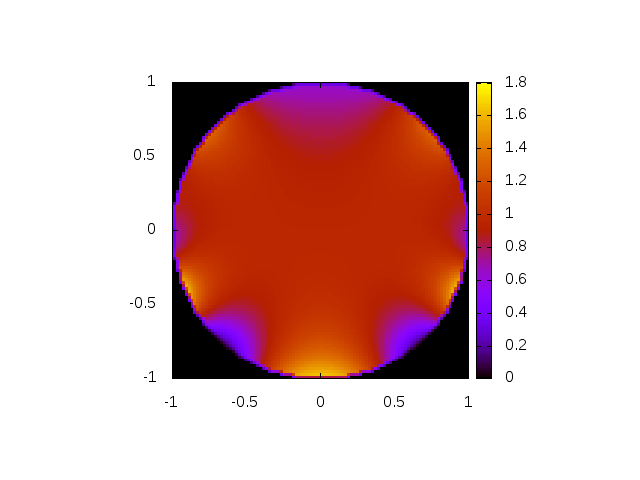
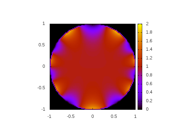
Figure 6: Transmission of the Ezsubscript𝐸𝑧E_{z} polarized plane wave propagating through an infinite 1D chain of dielectric cylinders. Top panel displays the transmission coefficient as a function of a/λ𝑎𝜆a/\lambda, calculated by the transfer matrix method and by the formula (18). Three Fano resonances correspond to maxims of coefficients β𝛽\beta shown in middle panel. Real part of the intensity of electric field inside the cylinder for three resonance frequencies, a/λ=0.549,0.759𝑎𝜆0.5490.759a/\lambda=0.549,~{}0.759 and 0.9580.9580.958 is shown in the bottom panel.

4 Interaction of external field with guided modes

We solve equations 16 and 17 and calculate transmission coefficient for incident plane wave with wavelength λ𝜆\lambda propagating along the y𝑦y direction. First, we express the coefficients Ek±subscriptsuperscript𝐸plus-or-minus𝑘E^{\pm}_{k} and hk±subscriptsuperscriptplus-or-minus𝑘h^{\pm}_{k}

ek+=hk+=Jk(v)(1+(1)k)/(1+δk0)k=0,1,ek=hk=Jk(v)(1(1)k),k=1,2,superscriptsubscript𝑒𝑘superscriptsubscript𝑘subscript𝐽𝑘𝑣1superscript1𝑘1subscript𝛿𝑘0𝑘01superscriptsubscript𝑒𝑘superscriptsubscript𝑘subscript𝐽𝑘𝑣1superscript1𝑘𝑘12\begin{array}[]{lclclr}e_{k}^{+}&=&h_{k}^{+}&=&J_{k}(v)(1+(-1)^{k})/(1+\delta_{k0})&k=0,1,\dots\\ e_{k}^{-}&=&h_{k}^{-}&=&J_{k}(v)(1-(-1)^{k}),&k=1,2,\dots\end{array} (22)

(v=2πR/λ𝑣2𝜋𝑅𝜆v=2\pi R/\lambda). From known coefficients β+superscript𝛽\beta^{+} and βsuperscript𝛽\beta^{-} we find spatial distribution of fields and calculate transmission coefficient given by equation 18.

4.1 Dielectric cylinders

Figure 6 shows the transmission coefficient for the Ezsubscript𝐸𝑧E_{z} polarized plane electromagnetic wave as a function of wavelength. Obtained results agree very well with numerical data calculated by the transfer matrix method [23, 24]. Typical Fano resonances in the transmission spectra [6, 7] are clearly visible and could be associated with excitation of corresponding guided modes [22] in cylinder chain. Owing to the symmetry of the incident wave which does not depend on x𝑥x, only modes symmetric with respect to xx𝑥𝑥x\to-x could be excited. Two even modes with k=2𝑘2k=2 and k=4𝑘4k=4 and one odd mode (k=3𝑘3k=3) have been excited. Bottom panels show the real part of electric field inside the cylinder and confirm predicted symmetry of excited states.

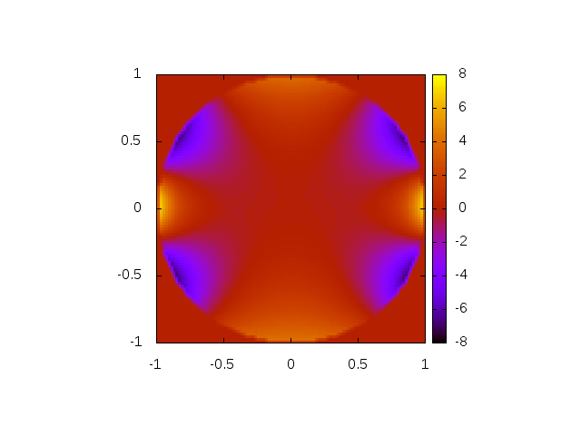
Similar results have been obtained also for the Hzsubscript𝐻𝑧H_{z} polarized incident wave shown in figure 7. In this case, two resonances of k=0𝑘0k=0 mode are clearly visible. The lower one, together with the first odd resonance, deform strongly the transmission spectrum. Three resonances observed at higher frequencies could be easily detected both from the transmission spectra and from the frequency dependence of parameters β𝛽\beta.

Refer to caption
Refer to caption
Refer to caption
Refer to caption
Figure 7: Transmission of the Hzsubscript𝐻𝑧H_{z} polarized plane wave propagating through an infinite chain of dielectric cylinders. Top panel displays the transmission coefficient as a function of a/λ𝑎𝜆a/\lambda, calculated by the transfer matrix method and by the formula equation 18. Fano resonances correspond to maxims of coefficients β𝛽\beta shown in middle panel. Real part of the intensity of magnetic field inside the cylinder for three resonance frequencies, a/λ=0.729,0.865𝑎𝜆0.7290.865a/\lambda=0.729,~{}0.865 and 0.9310.9310.931 is shown in the bottom panel.
Refer to caption
Refer to caption
Refer to caption
Refer to caption
Refer to caption
Refer to caption
Refer to caption
Refer to caption
Refer to caption
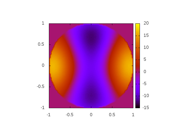
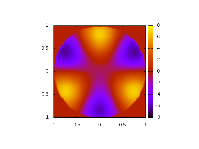
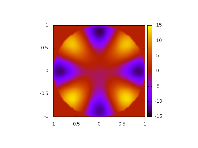
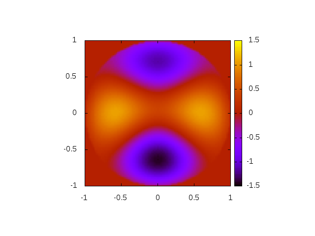
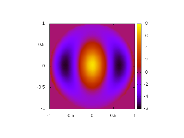
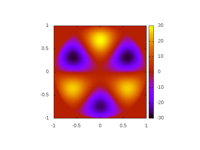
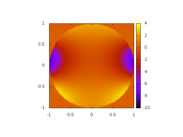
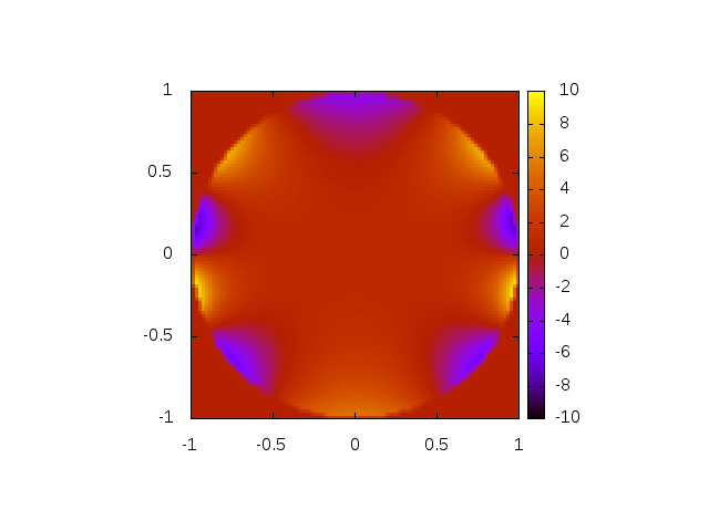
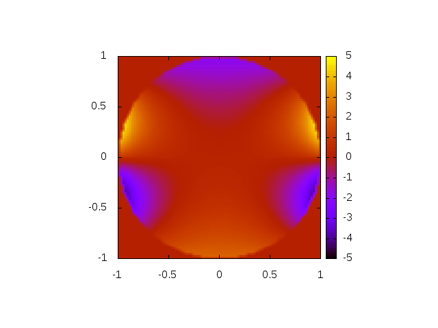
Figure 8: Left: transmission of the Ezsubscript𝐸𝑧E_{z} polarized electromagnetic wave through the linear chain of left-handed cylinders calculated by the transfer-matrix method with three different space discretization (120, 240 and 360 mesh points per unit cell). Middle: spectrum of coefficients β𝛽\beta. Note the scale of the vertical axis. Right panel shows the transmission coefficient calculated by the present method (equation 18 ). Bottom panel shows real part of the intensity of electric field inside the left-handed cylinder for frequencies associated with resonances of even modes (a/λ=0.027,0.078𝑎𝜆0.0270.078a/\lambda=0.027,~{}0.078 and 0.1840.1840.184), and odd modes (0.016,0.0470.0160.0470.016,~{}0.047 and 0.1400.1400.140).
Refer to caption
Refer to caption
Figure 9: Left: Transmission of Hzsubscript𝐻𝑧H_{z}-polarized plane wave through the chain of left-handed cylinders calculated by the transfer matrix method and from equation 18. Similarly to the case of dielectric cylinders, two numerical methods give identical result, because Fano resonances (shown in the right panel) are much weaker than in the case of Ezsubscript𝐸𝑧E_{z} polarized wave (Fig. 8).

4.2 Left-handed cylinders

The same analysis of the transmission spectra of cylinders made from the left-handed medium (ε=12𝜀12\varepsilon=-12, μ=1𝜇1\mu=-1) is more difficult, since standard numerical techniques (transfer matrix method, RCWA ) seem not to be suitable for the calculation of the transmission coefficient. As shown in the left panel of figure 8, results obtained by the transfer matrix method with three discretization of the unit cell provide us with completely different transmission coefficients. Such failure, obtained also when the transmission was calculated by the RCWA method indicates that the eigenstates of the electromagnetic field inside the structure are strongly inhomogeneous. Consequently, excited guided modes cannot be expanded in a finite series in the the basis of eigenfrequences, used in the transfer matrix method.

The assumption of strong spatial inhomogeneity is confirmed by frequency dependence of coefficients β𝛽\beta shown in middle panel of figure 8. Incident electromagnetic wave excites in the left-handed chain a series of guided modes. The resonant frequencies of these modes lie very close to each other (in fact, since the resonances have a finite width, they overlap). Also, absolute values of coefficients β𝛽\beta are in order of magnitude larger than in the case of dielectric cylinder.

Right panel of figure 8 shows the transmission coefficient obtained by equation (18). Two minims in the transmission coefficient coincide with eigenfrequences of excitation of guided modes. The spatial distribution of electric field shown in the bottom panel confirm that many resonances are excited simultaneously – in contrast to dielectric structure, we cannot easily identify the order of excited modes.

The above mentioned problem of numerical instability is not actual when transmission of the Hzsubscript𝐻𝑧H_{z} polarized wave is calculated (figure 9). Now, numerical data obtained by the transfer matrix method agree perfectly with those found by the present method (left panel). As shown in the right panel, resonances of guided modes are very weak and broad, so that they have negligible influence on the transmission coefficient.

5 Conclusion

We presented physical and numerical analysis of the guided modes of linear chain of cylinders, made either from the dielectric or from the left-handed material. Comparison of these two structures shows new phenomena could be observed when permittivity and permeability possess negative values. We proved that the transmission of electromagnetic waves through the photonic structure with left-handed components is strongly influenced by guided modes excited in the structure.

The spectrum of guided modes contains much more branches. In contrast to dielectric structure, the eigenfrequency of these modes decreases when mode index k𝑘k increases. Also, there are no guided modes for the wave vector close to some critical value qcsubscript𝑞𝑐q_{c}. We suppose that this absence of guided modes corresponds to the folding of frequency bands observed recently [15, 14].

Very rich spectrum of guided modes is responsible for numerical instabilities when the transmission coefficients is calculated by standard methods. Since eigenmodes of the left-handed structure strongly differs from plane waves, any numerical algorithm, based on the expansion of the fields into the plane waves (transfer matrix or RCWA) fails to recover true transmission coefficient.

6 Appendix A

For k,m=1,2,NBformulae-sequence𝑘𝑚12subscript𝑁𝐵k,m=1,2,\dots N_{B}, JkJk(2πR/λ)subscript𝐽𝑘subscript𝐽𝑘2𝜋𝑅𝜆J_{k}\equiv J_{k}(2\pi R/\lambda) and ksubscript𝑘{\cal H}_{k} given by equation 4 we obtain the N+1×N+1𝑁1𝑁1N+1\times N+1 matrix B

B00=0+n=1Ns2cosqH0(un)J0B0m=n=1NsHm(un)J0×[(1)meiqan+eiqan]Bk0=n=1NsHk(un)Jk×2[eiqan+(1)keiqan]Bkm=2kδkm+n=1Ns[eiqan(1)mk+eiqan][Hmk(un)+(1)kHm+k(un)]Jksubscript𝐵00subscript0superscriptsubscript𝑛1subscript𝑁𝑠2𝑞subscript𝐻0𝑢𝑛subscript𝐽0subscript𝐵0𝑚superscriptsubscript𝑛1subscript𝑁𝑠subscript𝐻𝑚𝑢𝑛subscript𝐽0delimited-[]superscript1𝑚superscript𝑒𝑖𝑞𝑎𝑛superscript𝑒𝑖𝑞𝑎𝑛subscript𝐵𝑘0superscriptsubscript𝑛1subscript𝑁𝑠subscript𝐻𝑘𝑢𝑛subscript𝐽𝑘2delimited-[]superscript𝑒𝑖𝑞𝑎𝑛superscript1𝑘superscript𝑒𝑖𝑞𝑎𝑛missing-subexpressionmissing-subexpressionmissing-subexpressionsubscript𝐵𝑘𝑚2subscript𝑘subscript𝛿𝑘𝑚superscriptsubscript𝑛1subscript𝑁𝑠delimited-[]superscript𝑒𝑖𝑞𝑎𝑛superscript1𝑚𝑘superscript𝑒𝑖𝑞𝑎𝑛delimited-[]subscript𝐻𝑚𝑘𝑢𝑛superscript1𝑘subscript𝐻𝑚𝑘𝑢𝑛subscript𝐽𝑘\begin{array}[]{lcl}B_{00}&=&{{\cal H}}_{0}+\displaystyle{\sum_{n=1}^{N_{s}}}~{}~{}2\cos qH_{0}(un)J_{0}\\ B_{0m}&=&\displaystyle{\sum_{n=1}^{N_{s}}}~{}~{}H_{m}(un)J_{0}\times[(-1)^{m}e^{iqan}+e^{-iqan}]\\ B_{k0}&=&\displaystyle{\sum_{n=1}^{N_{s}}}~{}~{}H_{k}(un)J_{k}\times 2[e^{iqan}+(-1)^{k}e^{-iqan}]\\ &&\\ B_{km}&=&2{{\cal H}}_{k}\delta_{km}+\displaystyle{\sum_{n=1}^{N_{s}}}~{}~{}[e^{iqan}(-1)^{m-k}+e^{-iqan}][H_{m-k}(un)+(-1)^{k}H_{m+k}(un)]J_{k}\end{array} (23)

and the N×N𝑁𝑁N\times N matrix C:

Ckm=2kδkm+n=1Ns[eiqan(1)mk+eiqan]×[mk(un)(1)km+k(un)]Jksubscript𝐶𝑘𝑚2subscript𝑘subscript𝛿𝑘𝑚superscriptsubscript𝑛1subscript𝑁𝑠missing-subexpressiondelimited-[]superscript𝑒𝑖𝑞𝑎𝑛superscript1𝑚𝑘superscript𝑒𝑖𝑞𝑎𝑛missing-subexpressiondelimited-[]subscript𝑚𝑘𝑢𝑛superscript1𝑘subscript𝑚𝑘𝑢𝑛subscript𝐽𝑘\begin{array}[]{lcl}C_{km}=2{{\cal H}}_{k}\delta_{km}+\displaystyle{\sum_{n=1}^{N_{s}}}&&[e^{iqan}(-1)^{m-k}+e^{-iqan}]\\ &\times&[{{\cal H}}_{m-k}(un)-(-1)^{k}{{\cal H}}_{m+k}(un)]J_{k}\end{array} (24)

Matrices B’ and C’ could be obtained from B and C, respectively, by substitutions

JkJk,kkformulae-sequencesubscript𝐽𝑘subscriptsuperscript𝐽𝑘subscript𝑘subscriptsuperscript𝑘J_{k}\to J^{\prime}_{k},~{}~{}~{}~{}~{}{{\cal H}}_{k}\to{{{\cal H}}^{\prime}}_{k} (25)

Acknowledgment

This work was supported by the Slovak Research and Development Agency under the contract No. APVV-0108-11 and by the Agency VEGA under the contract No. 1/0372/13.

References

References

  • [1] Joannopoulos J D, Johnson S G Winn J N and Meade R G 2008 Photonic Crystals: Molding the Flow of Light 2nd edition. (Princeton: Princeton University Press)
  • [2] Sakoda K 2005 Optical Properties of Photonic Crystals (Berlin, Heidelberg: Springer, 2005)
  • [3] Soukoulis C M (editor) 2001 Photonic Crystals and Light Localization in the 21st Century (Dordrecht: Kluver)
  • [4] Robertson W M et al. 1992 Phys. Rev. Lett. 68 2023
  • [5] Robertson W M et al. 1993 Optics Lett. 18 (1993)
  • [6] Fan S and Joannopoulos J D 2002 Phys. Rev. B 65 235112
  • [7] Fan S Suh W and Joannopoulos J D 2003 J. Opt. Soc. Amm. A 20 569
  • [8] Pendry J B et al. 1996 Phys. Rev. Lett. 76 4773
  • [9] Pokrovsky A L and Efros A L 2002 Phys. Rev. Lett. 89 093901
  • [10] Markoš P and Soukoulis C M 2003 Optics Lett. 28 846
  • [11] Pendry J B, Schurig D and Smith D R 2006 Science 312, 1780
  • [12] Engheta N and Ziolkowski R W (Editors) 2006 Metamaterials: Physics and Engineering Explorations. (New York: J. Wiley & Sons)
  • [13] Li J et al 2003 Phys. Rev. Lett. 90 083901
  • [14] Hermann D et al 2008 Phys. Rev. B 77 035112
  • [15] Chen P Y et al 2011 New J. Phys. 13 053007
  • [16] Kajtár G 2014 private communication
  • [17] Asatryan A A, Dossou K B and Botten L C 2008 Australian Institute of Physics, 18th national Congress
  • [18] Stratton J A 1941 Electromagnetic Theory (New York: Mc Graw-Hill Comp.)
  • [19] Abramowitz M and Stegun I A 1965 Handbook of Mathematical Functions (Dover Publ.)
  • [20] Press W H et al 1992 Numerical Recipes (Cambridge: Cambridge University Press)
  • [21] Pfeiffer C A, Economou E N and Ngai K L 1974 Phys. Rev. B 10, 3038
  • [22] Astratov V N et al 1999 J. Light. Technol. 17 2050
  • [23] Pendry J B and MacKinnon A 1992 Phys. Rev. Lett. 69 2772
  • [24] Markoš P and Soukoulis C M 2002 Phys. Rev. E 65 036622