Enabling High-level Application Development for the Internet of Things
Abstract
Application development in the Internet of Things (IoT) is challenging because it involves dealing with a wide range of related issues such as lack of separation of concerns, and lack of high-level of abstractions to address both the large scale and heterogeneity. Moreover, stakeholders involved in the application development have to address issues that can be attributed to different life-cycles phases. when developing applications. First, the application logic has to be analyzed and then separated into a set of distributed tasks for an underlying network. Then, the tasks have to be implemented for the specific hardware. Apart from handling these issues, they have to deal with other aspects of life-cycle such as changes in application requirements and deployed devices.
Several approaches have been proposed in the closely related fields of wireless sensor network, ubiquitous and pervasive computing, and software engineering in general to address the above challenges. However, existing approaches only cover limited subsets of the above mentioned challenges when applied to the IoT. This paper proposes an integrated approach for addressing the above mentioned challenges. The main contributions of this paper are: (1) a development methodology that separates IoT application development into different concerns and provides a conceptual framework to develop an application, (2) a development framework that implements the development methodology to support actions of stakeholders. The development framework provides a set of modeling languages to specify each development concern and abstracts the scale and heterogeneity related complexity. It integrates code generation, task-mapping, and linking techniques to provide automation. Code generation supports the application development phase by producing a programming framework that allows stakeholders to focus on the application logic, while our mapping and linking techniques together support the deployment phase by producing device-specific code to result in a distributed system collaboratively hosted by individual devices. Our evaluation based on two realistic scenarios shows that the use of our approach improves the productivity of stakeholders involved in the application development.
1 Introduction
The recent technological advances have been fueling a tremendous growth in a number of smart objects [65, p. 3] such as temperature sensors, smoke detectors, fire alarms, parking space controllers. They can sense the physical world by obtaining information from sensors, affect the physical world by triggering actions using actuators, engage users by interacting with them whenever necessary, and process captured data and communicate it to outside world. In the Internet of Things [10], smart objects (or “things”) acquire intelligence thanks to the fact that they can communicate with each other and cooperate with their neighbors to reach a common goal [2]. For example, a building interacts with its residents and surrounding buildings in case of fire for safety and security of residents, offices adjust themselves automatically accordingly to user preferences while minimizing energy consumption, or traffic signals control in-flow of vehicles according to the current highway status [55].
As evident above, IoT applications will involve interactions among large numbers of disparate devices, many of them directly interacting with their physical surroundings. An important challenge that needs to be addressed in the IoT, therefore, is to enable the rapid development of IoT applications with minimal effort by the various stakeholders111Throughout this paper, we use the term stakeholders as used in software engineering to mean – people, who are involved in the application development. Examples of stakeholders defined in [63] are software designer, developer, domain expert, technologist, etc. involved in the process. Similar challenges have already been addressed in the closely related fields of Wireless Sensor Networks (WSNs) [65, p. 11] and ubiquitous and pervasive computing [65, p. 7], regarded as precursors to the modern day IoT. While the main challenge in the former is the large scale – hundreds to thousands of largely similar devices, the primary concern in the latter has been the heterogeneity of devices and the major role that the user’s own interaction with these devices plays in these systems (cf. the classic “smart home” scenario where a user controls lights and receives notifications from his refrigerator and toaster.). It is the goal of our work to enable the development of such applications. In the following, we discuss one of such applications.
1.1 Application example
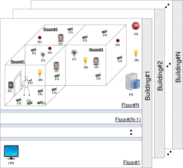
We consider a hypothetical building system utilized by a company. This building system might consist of several buildings, with each building in turn consisting of one or more floors, each with several rooms. It may consist of a large number of heterogeneous devices equipped with sensors, actuators, storage, user interfaces. Figure 1 describes the building automation domain with various devices. Many applications can be developed using these devices, one of which we discuss below.
Smart building application. To accommodate the mobile worker’s preference in the reserved room, a database is used to keep the profile of each worker, including his preferred lighting and temperature level. A badge reader in the room detects the worker’s entry event and queries the database for the worker’s preference. Based on this, the thresholds used by the room’s devices are updated. To reduce electricity waste when a person leaves the room, detected by badge disappeared event, lighting and heating level are automatically set to the lowest level; all according to the building’s policy. The system may also include user interfaces that allow a late worker to control heater of his room and request the profile database to get his lighting and temperature preferences. Moreover, the system generates the current status (e.g., temperature, energy consumption) of each room, which is then aggregated and used to determine the current status of each floor and, in turn, the entire building. A monitor installed at the building entrance presents the information to the building operator for situational awareness.
1.2 IoT application development challenges
This section reviews the application development challenges as gleaned from our analysis of applications such as the one discussed in the previous section. The challenges we address in this work are as follows:
Lack of division of roles. IoT application development is a multi-disciplined process where knowledge from multiple concerns intersects. Traditional IoT application development assumes that the individuals involved in the application development have similar skills. This is in clear conflict with the varied set of skills required during the process, including domain expertise (e.g., the smart building application reason in terms of rooms and floors, the smart city applications are expressed in terms of sectors.), deployment-specific knowledge (e.g., understanding of the specific target area where the application is to be deployed, mapping of processing components to devices in the target deployment), application design and implementation knowledge, and platform-specific knowledge (e.g., Android-specific APIs to get data from sensors, vendor-specific database such as MySQL), a challenge recognized by recent works such as [14, 51].
Heterogeneity. IoT applications execute on a network consisting of heterogeneous devices in terms of types (e.g., sensing, actuating, storage, and user interface devices), interaction modes (e.g. Publish/Subscribe [21], Request/Response [3], Command [1]), as well as different platforms (e.g., Android mobile OS, Java SE on laptops). The heterogeneity largely spreads into the application code and makes the portability of code to a different deployment difficult.
Scale. As mentioned above, IoT applications execute on distributed systems consisting of hundreds to thousands of devices, involving the coordination of their activities (e.g., temperature values are computed at per-room and then per-floor levels to calculate an average temperature value of a building). Requiring the ability of reasoning at such levels of scale is impractical in general, as has been largely the view in the WSN community.
Different life cycle phases. Stakeholders have to address issues that are attributed to different life cycles phases,including development, deployment, and maintenance [7]. At the development phase, the application logic has to be analyzed and separated into a set of distributed tasks for the underlying network consisting of a large number of heterogeneous entities. Then, the tasks have to be implemented for the specific platform of a device. At the deployment phase, the application logic has to be deployed onto a large number of devices. Apart from handling these issues, stakeholders have to keep in mind evolution issues both in the development (change in functionality of an application such as the smart building application is extended by including fire detection functionality) and deployment phase (e.g. adding/removing devices in deployment scenarios such as more temperature sensors are added to sense accurate temperature values in the building) at the maintenance phase. Manual effort in all above three phases for hundreds to thousands of heterogeneous devices is a time-consuming and error-prone process.
In order to address the above mentioned challenges, various approaches have been proposed (for a detailed discussion of various systems available for application development, refer Section 5). One of the approach is node-centric programming [66, 54, 16]. It allows for the development of extremely efficient systems based on complete control over individual devices. However, it is not easy to use for IoT applications due to the large size and heterogeneity of systems. In order to address node-centric programming limitation, various macroprogramming systems [49, 7] have been proposed. However, most of macroprogramming systems largely focus on development phase while ignoring the fact that it represents a tiny fraction of the application development life-cycle. The lack of a software engineering methodology to support the entire application development life-cycle commonly results in highly difficult to maintain, reuse, and platform-dependent design, which can be tackled by the model-driven approach. To address the limitations of macroprogramming systems, approaches based on model-driven design (MDD) have been proposed [57, 24, 40, 37]. Major benefits came from the basic idea that by separating different concerns of a system at a certain level of abstraction, and by providing transformation engines to convert these abstractions to a target code, productivity (e.g., reusability, maintainability) in the application development process can be improved.
1.3 Contributions
Our aim is to make IoT application development easy for stakeholders as is the case in software engineering in general, by taking inspiration from the MDD approach and building upon work in sensor network macroprogramming. We achieve this aim by separating IoT application development into different concerns and integrating a set of high-level languages222Please note that high-level languages (e.g., AADL, EAST-ADL, SysML, etc.) for IoT have been investigated at length in the domains of pervasive/ubiquitous computing and wireless sensor network. However, their integration to our development framework in an appropriate way is our contribution. to specify them. We provide automation techniques at different phases of IoT application development to reduce development effort. We now present these contributions in detail described below:
Development methodology. We propose a development methodology that defines a precise sequence of steps to be followed to develop IoT applications, thus facilitating IoT application development. These steps are separated into four concerns, namely, domain, functional, deployment, and platform. This separation allows stakeholders to deal with them individually and reuse them across applications. Each concern is matched with a precise stakeholder according to skills. The clear identification of expectations and specialized skills of each type of stakeholders helps them to play their part effectively.
Development framework. To support the actions of each stakeholder, the development methodology is implemented as a concrete development framework333It includes support programs, code libraries, high-level languages or other software that help stakeholders to develop and glue together different components of a software product.. It provides a set of modeling languages, each named after “Srijan”,444Srijan is the sanskrit word for “creation”. and offers automation techniques at different phases of IoT application development, including the following:
-
1.
A set of modeling languages. To aid stakeholders, the development framework integrates three modeling languages that abstract the scale and heterogeneity-related complexity: (1) Srijan Vocabulary Language (SVL) to describe domain-specific features of an IoT application, (2) Srijan Architecture Language (SAL) to describe application-specific functionality of an IoT application, (3) Srijan Deployment Language (SDL) to describe deployment-specific features consisting information about a physical environment where devices are deployed.
-
2.
Automation techniques. The development framework is supported by code-generation, task-mapping, and linking techniques. These three techniques together provide automation at various phases of IoT application development. Code generation supports the application development phase by producing a programming framework that reduces the effort in specifying the details of the components of an IoT application. Mapping and linking together support the deployment phase by producing device-specific code to result in a distributed system collaboratively hosted by individual devices.
Our work on the above is supported at the lower layers by a middleware that enables delivery of messages across physical regions, thus enabling our abstractions for managing large scales in the Internet of Things.
Outline. The remainder of this paper is organized as follows: Section 2 presents our development methodology and its development framework. This includes details of on modeling languages, automation techniques, and our approach for handling evolutions. Section 3 presents an implementation of our development framework. We present tools, technologies, and programming languages used to implement this development framework. Section 4 evaluates the development framework in a quantitative manner. Section 5 explores state of the art approaches for developing IoT applications. Section 6 summarizes this paper and Section 7 describes briefly some future directions of this work.
2 Our approach to IoT application development
Applying separation of concerns design principal from software engineering, we break the identified concepts and associations among them into different concerns represented in Conceptual model [48], described in Section 2.1. The identified concepts are linked together into a well-defined and structured methodology, described in Section 2.2. We implement the proposed development methodology as a concrete development framework [47, 46, 61, 45], presented in Section 2.3.
2.1 Conceptual model
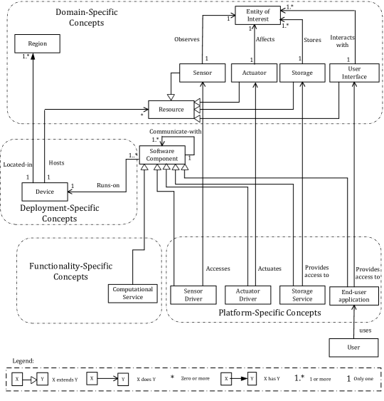
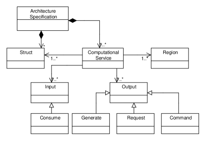
A conceptual model often serves as a base of knowledge about a problem area [23]. It represents the concepts as well as the associations among them and also attempts to clarify the meaning of various terms. Taking inspiration from previous efforts [7, 12, 18], we have identified four major concerns for IoT application development. Figure 2 illustrates the concepts and their associations along with these four separate concerns: (1) domain-specific concepts, (2) functionality-specific concepts, (3) deployment-specific concepts, and (4) platform-specific concepts.
2.1.1 Domain-specific concepts
The concepts that fall into this category are specific to a target application domain (e.g., building automation, transport, etc.). For example, the building automation domain is reasoned in terms of rooms and floors, while the transport domain is expressed in terms of highway sectors. Furthermore, each domain has a set of entities of interest (e.g., average temperature of a building, smoke presence in a room), which are observed and controlled by sensors and actuators respectively. Storages store information about entities of interest, and user interfaces enable users to interact with entities of interest (e.g., receiving notification in case of fire in a building, controlling the temperature of a room). We describe these concepts in detail below:
-
1.
An Entity of Interest (EoI) is an object (e.g., room, book, plant), including attributes that describe it, and its state that is relevant from a user or an application perspective [31, p. 1]. The entity of interest has an observable property called phenomenon. Typical examples are the temperature value of a room and a tag ID.
-
2.
A resource is a conceptual representation of a sensor, an actuator, a storage, or a user interface. We consider the following types of resources:
-
(a)
A sensor has the ability to detect changes in the environment. Thermometer and tag readers are examples of sensors. The sensor observes a phenomenon of an EoI. For instance, a temperature sensor observes the temperature phenomenon of a room.
-
(b)
An actuator makes changes in the environment through an action. Heating or cooling elements, speakers, lights are examples of actuators. The actuator affects a phenomenon of an EoI by performing actions. For instance, a heater is set to control a temperature level of a room.
-
(c)
A storage has the ability of storing data in a persistent manner. The storage stores information about a phenomenon of an EoI. For instance, a database server stores information about an employee’s temperature preference.
-
(d)
A user interface represents tasks available to users to interact with entities of interest. For the building automation domain, a task could be receiving a fire notification in case of emergency or controlling a heater according to a temperature preference.
-
(a)
-
3.
A device is located in a region [64]. The region is used to specify the location of a device. In the building automation domain, a region (or location) of a device can be expressed in terms of building, room, and floor IDs.
2.1.2 Functionality-specific concepts
The concepts that fall into this category describe computational elements of an application and interactions among them. A computational element is a type of software component, which is an architectural entity that (1) encapsulates a subset of the system’s functionality and/or data, (2) restricts access to that subset via an explicitly defined interface [63, p. 69]. We use the term application logic to refer a functionality of a software component. An example of the application logic is to open a window when the average temperature value of a room is greater than .
The conceptual model contains the following functionality-specific software component, a computational service, which is a type of software component that consumes one or more units of information as inputs, processes it, and generates an output. An output could be data message that is consumed by others or a command message that triggers an action of an actuator. A computational service is a representation of the processing element in an application.
A software component communicates-with other software components to exchange data or control. These interactions might contain instances of various interaction modes such as request-response, publish-subscribe, and command. Note that this is in principle an instance of the component-port-connector architecture used in software engineering.
2.1.3 Deployment-specific concepts
The concepts that fall into this category describe information about devices. Each device hosts zero or more resources. For example, a device could host resources such as a temperature sensor to sense, a heater to control a temperature level, a monitor to display a temperature value, a storage to store temperature readings, etc. Each device is located-in regions. For instance, a device is located-in room#1 of floor#12 in building#14. We consider the following definition of a device:
-
1.
A device is an entity that provides resources the ability of interacting with other devices. Mobile phones, and personal computers are examples of devices.
2.1.4 Platform-specific concepts
The concepts that fall into this category are computer programs that act as a (operating system-specific) translator between a hardware device and an application. We identify the following platform-specific concepts:
-
1.
A sensor driver is a type of software component that operates on a sensor attached to a device. It accesses data observed by the sensor and generates the meaningful data that can be used by other software components. For instance, a temperature sensor driver generates temperature values and its meta-data such as unit of measurement, time of sensing. Another software component takes this temperature data as input and calculates the average temperature of the room.
-
2.
An actuator driver is a type of software component that controls an actuator attached to a device. It translates a command from other software components and actuates the actuator appropriately. For instance, a heater driver translates a command “turn the heater on” to regulate the temperature level.
-
3.
A storage service is a type of software component that provides a read and write access to a storage. A storage service provides access to the storage. Other software components access data from the storage by requesting the storage service. For instance, MySQL storage service provides access to a database server.
-
4.
An end-user application is a type of software component that is designed to help a user to perform tasks (e.g., receiving notifications, submitting information). It provides access to available tasks. For instance, in the smart building application a user could provide his temperature preferences using an application installed on his smart phone.
The next section presents a development methodology that links the above four concerns and provides a conceptual framework to develop IoT applications.
2.2 A development methodology
To make IoT application development easy, stakeholders should be provided a structured and well-defined application development process (referred to as development methodology). This section presents a development methodology that integrates different development concerns discussed in Section 2.1 and provides a conceptual framework for IoT application development. In addition to this, it assigns a precise role to each stakeholder commensurate with his skills and responsibilities.
As stated in Section 1.2, IoT application development is a multi-disciplined process where knowledge from multiple concerns intersects. So far, IoT application development assumes that the individuals have similar skills. While this may be true for simple/small applications for single-use deployments, as the IoT gains wide acceptance, the need for sound software engineering approaches to adequately manage the development of complex applications arises.
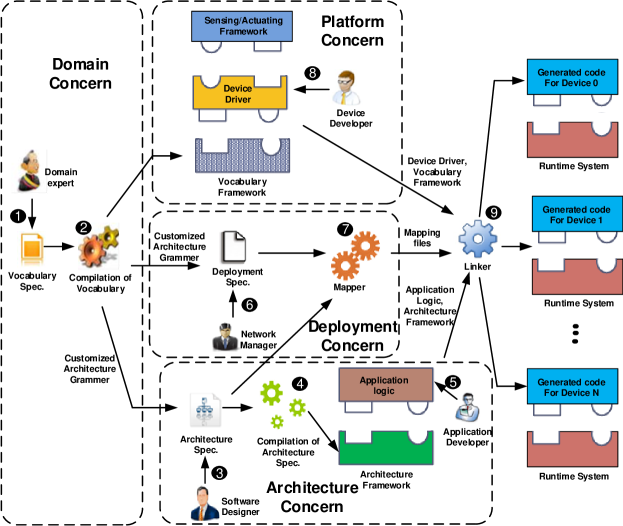
Taking inspiration from ideas proposed in the 4+1 view model of software architecture [36], collaboration model for smart spaces [14], and tool-based methodology for pervasive computing [12], we propose a development methodology that provides a conceptual framework to develop an IoT application (detailed in Figure 3). The development methodology divides the responsibilities of stakeholders into five distinct roles —domain expert, software designer, application developer, device developer, and network manager. Note that although these roles have been discussed in the software engineering literature in general, e.g., domain expert and software designer in [63, p. 657], application developer [12, p. 3], their clear identification for IoT applications is largely missing. Due to the existence of various, slightly varying, definitions in literature, we summarize the skills and responsibilities of the various stakeholders in Table 1
| Role | Skills | Responsibilities |
|---|---|---|
| Domain expert | Understands domain concepts, including the data types produced by the sensors, consumed by actuators, accessed from storages, user’s interactions, and how the system is divided into regions. | Specify the vocabulary of an application domain to be used by applications in the domain. |
| Software designer | Software architecture concepts, including the proper use of interaction modes such as publish-subscribe, command, and request-response for use in the application. | Define the structure of an IoT application by specifying the software components and their generate, consume, and command relationships. |
| Application developer | Skilled in algorithm design and use of programming languages. | Develop the application logic of the computational services in the application. |
| Device developer | Deep understanding of the inputs/outputs, and protocols of the individual devices. | Write drivers for the sensors, actuators, storages, and end-user applications used in the domain. |
| Network manager | Deep understanding of the specific target area where the application is to be deployed. | Install the application on the system at hand; this process may involve the generation of binaries or bytecode, and configuring middleware. |
An application corresponds to a specific application domain (e.g., building automation, health-care, transport) consisting of domain-specific concepts. Keeping this in mind, we separate the domain concern from other concerns (see Figure 3, stage 1). The main advantage of this separation is that domain-specific knowledge can be made available to stakeholders and reused across applications of a same application domain.
IoT applications closely interact with the physical world. Consequently, changes in either of them have a direct influence on the other. The changes could be technological advances with new software features, a change in functionality of an application, a change in distribution of devices, and adding or replacing devices. Considering this aspect, we separate IoT application development into the platform, functional, and deployment concern at the second stage (see Figure 3, stage 2). Thus, stakeholders can deal with them individually and reuse them across applications. The final stage combines and packs the code generated by the second stage into packages that be deployed on devices (see Figure 3, stage 3).
2.3 Development framework
To support actions of stakeholders, the development methodology discussed in Section 2.2 is implemented as a concrete development framework. This section presents this development framework that provides a set of modeling languages, each named after Srijan, and offers automation techniques at different phases of IoT application development for the respective concerns.
2.3.1 Domain concern
This concern is related to domain-specific concepts of an IoT application. It consists of the following steps:
-
1.
Specifying domain vocabulary. The domain expert specifies a domain vocabulary (step in Figure 3) using the Srijan Vocabulary Language (SVL). The vocabulary includes specification of resources, which are responsible for interacting with entities of interest. In the vocabulary, resources are specified in a high-level manner to abstract low-level details from the domain expert. Moreover, the vocabulary includes definitions of regions that define spatial partitions (e.g., room, floor, building) of a system.
-
2.
Compiling vocabulary specification. Leveraging the vocabulary, the development framework generates (step in Figure 3): (1) a vocabulary framework to aid the device developer, (2) a customized architecture grammar according to the vocabulary to aid the software designer, and (3) a customized deployment grammar according to the vocabulary to aid the network manager. The key advantage of this customization is that the domain-specific concepts defined in the vocabulary are made available to other stakeholders and can be reused across applications of the same application domain.
2.3.2 Functional concern
This concern is related to functionality-specific concepts of an IoT application. It consists of the following steps:
-
1.
Specifying application architecture. Using a customized architecture grammar, the software designer specifies an application architecture (step in Figure 3) using the Srijan Architecture Language (SAL). SAL is an architecture description language (ADL) designed for specifying computational services and their interactions with other software components. To facilitate scalable operations within IoT applications, SAL offers scope constructs. These constructs allow the software designer to group devices based on their spatial relationship to form a cluster (e.g., “devices are in room#1”) and to place a cluster head to receive and process data from that cluster. The grouping and cluster head mechanism can be recursively applied to form a hierarchical clustering that facilitates the scalable operations within IoT applications.
-
2.
Compiling architecture specification. The development framework leverages an architecture specification to support the application developer (step in Figure 3). To describe the application logic of each computational service, the application developer is provided an architecture framework, pre-configured according to the architecture specification of an application, an approach similar to the one discussed in [11].
-
3.
Implementing application logic. To describe the application logic of each computational service, the application developer leverages a generated architecture framework (step in Figure 3). It contains abstract classes555We assume that the application developer uses an object-oriented language., corresponding to each computational service, that hide interaction details with other software components and allow the application developer to focus only on application logic. The application developer implements only the abstract methods of generated abstract classes.
2.3.3 Deployment concern
This concern is related to deployment-specific concepts of an IoT application. It consists of the following steps:
-
1.
Specifying target deployment. Using a customized deployment grammar, the network manager describes a deployment specification (step in Figure 3) using the Srijan Deployment Language (SDL). The deployment specification includes the details of each device666Our work excludes low-end computing devices (e.g., SunSpoT, TelosB, Tmote Sky, etc.). We believe this is a reasonable assumption because technological advances in embedded system result into devices with more and more computational power and memory., including its regions (in terms of values of the regions defined in the vocabulary), resources hosted by devices (a subset of those defined in the vocabulary), and the type of the device. Ideally, the same IoT application could be deployed on different target deployments (e.g., the same inventory tracking application can be deployed in different warehouses). This requirement is dictated by separating a deployment specification from other specifications.
-
2.
Mapping. The mapper produces a mapping from a set of computational services to a set of devices (step in Figure 3). It takes as input a set of placement rules of computational services from an architecture specification and a set of devices defined in a deployment specification. The mapper decides devices where each computational service will be deployed.
2.3.4 Platform concern
This concern is related to platform-specific concepts of an IoT application. It consists of the following step:
-
1.
Implementing device drivers. Leveraging the vocabulary, our system generates a vocabulary framework to aid the device developer (step in Figure 3). The vocabulary framework contains interfaces and concrete classes corresponding to resources defined in the vocabulary. The concrete classes contain concrete methods for interacting with other software components and platform-specific device drivers. The interfaces are implemented by the device developer to write platform-specific device drivers.
2.3.5 Linking
The linker combines and packs code generated by various stages into packages that can be deployed on devices. It merges generated architecture framework, application logic, mapping files, device drivers, and vocabulary framework (step in Figure 3). This stage supports the application deployment phase by producing device-specific code to result in a distributed software system collaboratively hosted by individual devices, thus providing automation at the deployment phase777We assume that a middleware is already installed on the deployed devices. The installed middleware enables inter-device communication among devices..
2.3.6 Handling evolution
Evolution is an important aspect in IoT application development where new resources and computational services are added, removed, or extended. To deal with these changes, our development framework separates IoT application development into different concerns and allows an iterative development [60] for these concerns.
This next section provides the details of our approach including three modeling languages (SVL, SAL, and SDL), programming frameworks to aid stakeholders, and an approach for handling evolution. This section refers to the building automation domain discussed in Section 1.1 for describing examples.
2.4 Specifying domain concern with the SVL
The domain concern describes an application domain of an IoT application. The domain expert specifies it using SVL. A vocabulary includes specification of resources that are responsible for interacting with entities of interest, including sensors, actuators, storages, and user interfaces. Moreover, it includes region definitions specific to the application domain. We now present SVL for describing the domain concern.
SVL is designed to enable the domain expert to describe a domain vocabulary domain. It offers constructs to specify concepts that interact with entities of interest. Figure 4 illustrates domain-specific concepts (defined in the conceptual model Figure 2) that can be specified using SVL. These concepts can be described as . represents the set of regions, represents the set of data structure, and represents the set of resources. We describe these concepts in detail as follows:
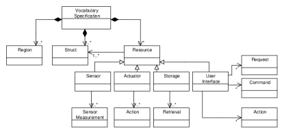
regions (). It represents the set of regions that are used to specify locations of devices. A region definition includes a region label and region type. For example, the building automation is reasoned in terms of rooms and floors (considered as region labels), while the transport domain is expressed in terms of highway sectors. Each room or floor in a building may be annotated with an integer value (e.g. room:1 interprets as room number 1) considered as region type. This construct is declared using the regions keyword. Listing 1 (lines 1-4) shows region definitions for the building automation domain.
data structures (). Each resource is characterized by types of information it generates or consumes. A set of information is defined using the structs keyword (Listing 1, line 5). For instance, a temperature sensor may generate a temperature value and unit of measurement (e.g., Celsius or Fahrenheit). This information is defined as TempStruct and its two fields (Listing 1, lines 9-11).
resources (). It defines resources that might be attached with devices, including sensors, actuators, storages, or user interfaces. It is defined as . represents a set of sensors, represents a set of actuators, represents a set of storages, and represents a set of user interfaces. We describe them in detail as follows:
-
1.
sensors (): It defines a set of various types of sensors (e.g., temperature sensor, smoke detector). A set of sensors is declared using the sensors keyword (Listing 1, line 13). is a set of sensor measurements produced by . Each sensor () produces one or more sensor measurements () along with the data-types specified in the data structure (). A sensor measurement of each sensor is declared using the generate keyword (Listing 1, line 17). For instance, a temperature sensor generates a temperature measurement of Tempstruct type (lines 16-17) defined in data structures (lines 9-11).
-
2.
actuators (): It defines a set of various types of actuator888 Since a deployment infrastructure may be shared among a number of different IoT applications and users, it is likely that these applications may have actuation conflicts. This work assumes actuators are pre-configured which can resolve actuation conflicts. (e.g., heater, alarm). A set of actuators is declared using the actuators keyword (Listing 1, line 18). is a set of actions performed by . Each actuator () has one or more actions () that is declared using the action keyword. An action of an actuator may take inputs specified as parameters of an action (Listing 1, line 21). For instance, a heater may has two actions. One is to switch off the heater and second is to set the heater according to a user’s temperature preference illustrated in Listing 1, lines 19-21. The SetTemp action takes a user’s temperature preference shown in line 21.
-
3.
storages (): It defines a set of storages999Even though IoT applications may include rich diverse set of storages available today on the Internet (e.g., RDBMs and noSQL databases, using content that is both user generated such as photos as well as machine generated such as sensor data), we restrict our work to key-value data storage services. (e.g., user’s profile storage) that might be attached to a device. A set of storages is declared using the storages keyword (Listing 1, line 22). represents a set of retrievals of . A retrieval () from the storage () requires a parameter. Such a parameter is specified using the accessed-by keyword (Listing 1, line 24). For instance, a user’s profile is accessed from profile storage by his unique badge identification illustrated in Listing 1, lines 23-24.
-
4.
user interfaces (): It defines a set of tasks (e.g., controlling a heater, receiving notification from a fire alarm, or requesting preference information from a database server) available to users to interact with other entities. A set of user interfaces is declared using the user interfaces keyword (Listing 1, line 25). The user interface provides the following tasks:
- (a)
-
(b)
action (): It is a set of actions that can be invoked by other entities to notify users, represented as . The other resources may notify a user (e.g., notify the current temperature) by invoking an action provided by the user interface. The notification task is declared using the action keyword (Listing 1, line 28).
- (c)
The regions (), data structures (), and resources () defined using SVL in the vocabulary are used to customize the grammar of SAL, and can be exploited by tools to provide support such as code completion to the software designer, discussed next.
2.5 Specifying functional concern
This concern describes computational services and how they interact with each other to describe functionality of an application. We describe the computational services and interactions among them using SAL (discussed in Section 2.5.1). The development framework customizes the SAL grammar to make domain-specific knowledge defined in the vocabulary available to the software designer and use it to generate an architecture framework. The application developer leverages this generated framework and implements the application logic on top of it (discussed in Section 2.5.2).
2.5.1 Srijan architecture language (SAL)
Based on a vocabulary, the SAL grammar is customized to enable the software designer to design an application. Specifically, sensors (), actuators (), storages (), user interfaces (), and regions () defined in the vocabulary become possible set of values for certain attributes in SAL (see underlined words in Listing 2).
Figure 5 illustrates concepts related-to a computational service that can be specified using SAL. It can be described as . represents a set of computational services. It is described as . represents a set of outputs produced by computational services. is a set of inputs consumed by computational services. The inputs could be data produced by other computational services or sensors (). represents a set of request by computational services to retrieve data from the storages (). represents a set of commands to invoke actuators () or user interfaces (). is a set of regions () where computational services can be placed. is a set of regions () where computational services receive data. In the following, we describe these concepts in detail.
consume () and generate (). These two concepts together define publish/subscribe interaction mode that provides subscribers with the ability to express their interest in an event, generated by a publisher, that matches their registered interest. A computational service represents the publish and subscribe using generate and consume concept respectively. We describe these two concepts in details as follows:
-
1.
consume: It represents a set of subscriptions (or consumes) expressed by computational services to get event notifications generated by sensors () defined in the vocabulary specification or other computational services () defined in the architecture specification. Thus, can be . A consume () of a computational service is expressed using the consume keyword. The computational service expresses its interest by an event name. For instance, a computational service RoomAvgTemp, which calculates an average temperature of a room, subscribes its interest by expressing event name tempMeasurement illustrated in Listing 2, line 9.
-
2.
generate: It represents a set of publications (or generates) that are produced by computational services. A generate () of a computational service is expressed using the generate keyword. The computational service transforms data to be consumed by other computational services in accordance with the application needs. For instance, the computational service RoomAvgTemp consumes temperature measurements (i.e., tempMeasurement), calculates an average temperature of a room, and generates roomAvgTempMeasurement (Listing 2, lines 7-9) that is used by RoomController service (Listing 2, lines 11-12).
request (). It is a set of requests, issued by computational services, to retrieve data from storages () defined in the vocabulary specification. A request is a one-to-one synchronous interaction with a return values. In order to fetch data, a requester sends a request message containing an access parameter to a responder. The responder receives and processes the request message, ultimately returns an appropriate message as a response. An access () of the computational service is specified using request keyword. For instance, a computational service Proximity (Listing 2, line 5), which wants to access user’s profile data, sends a request message containing profile information as an access parameter to a storage ProfileDB (Listing 1, line 24).
command (). It is a set of commands, issued by a computational service to trigger actions provided by actuators () or user interfaces (). So, it can be a subset of . The software designer can pass arguments to a command depend on action signature provided by actuators or user interfaces. Moreover, he specifies a scope of command, which specifies a region where commands are issued. A command is specified using the command keyword. An example of command invocation is given in line 14 of Listing 2. The room controller service (i.e., roomController), which regulates temperature, issues a SetTemp command with a preferred temperature as an argument (i.e., settemp) to heaters (Listing 1, line 21).
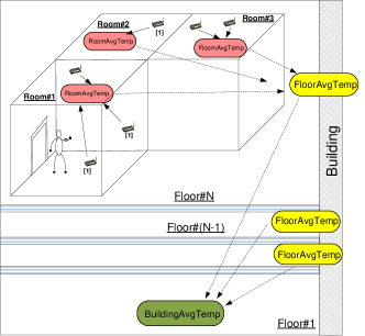
in-region () and hops (). To facilitate the scalable operations within an IoT application, devices should be grouped to form a cluster based on their spatial relationship [59] (e.g.,“devices are in room#1”). The grouping could be recursively applied to form a hierarchy of clusters. Within a cluster, a computational service is placed to receive and process data from its cluster of interest. Figure 6 shows this concept for more clarity. The temperature data is first routed to a local average temperature service (i.e., RoomAvgTemp), deployed in per room, then later per floor (i.e., FloorAvgTemp), and then ultimately routed to building average temperature service (i.e., BuildingAvgTemp).
SAL offers scope constructs to define both the service placement () and its data interest (). The service placement (defined using the in-region keyword) is used to govern a placement of computational service in a cluster. The service placement can be in regions defined in a vocabulary specification. So, it is a subset of .
The data interest of a computational service is used to define a cluster from which the computational service wants to receive data. The data interest can be in regions defined in the vocabulary specification. So, it is a subset of . It is defined using the hops keyword. The syntax of this keyword is hops:radius:unit of radius. Radius is an integer value. The unit of radius is a cluster value. For example, if a computational service FloorAvgTemp deployed on floor number 12 has a data interest hops:i:Floor, then it wants data from all floors starting from 12-th floor to (12+i)-th floor, and all floors starting from 12-th floor to (12-i)-th floor .
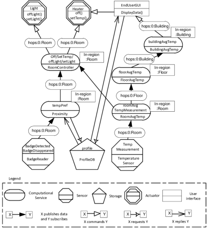
Figure 7 shows the architecture of the smart building application. Computational services are fueled by sensing components. They process inputs data and take appropriate decisions by triggering actuators. We illustrate SAL by examining a code snippet in Listing 2, which describes a part of Figure 7. This code snippet revolves around the actions of the Proximity service (Listing 2, lines 2-6), which coordinates events from the BadgeReader with the content of ProfileDB storage service. To do so, the Proximity composes information from two sources, one for badge events (i.e., badge detection), and one for requesting the user’s temperature profile from ProfileDB, expressed using the request keyword (Listing 2, line 5). Input data is declared using the consume keyword that takes source name and data interest of a computational service from logical region (Listing 2, line 4). The declaration of hops:0:room indicates that the computational service is interested in consuming badge events of the current room. The Proximity service is in charge of managing badge events of room. Therefore, we need Proximity service to be partitioned per room using in-region:room (Listing 2, line 6). The outputs of the Proximity and RoomAvgTemp are consumed by the RoomController service (Listing 2, lines 11-15). This service is responsible for taking decisions that are carried out by invoking commands declared using the command keyword (Listing 2, line 14).
2.5.2 Implementing application logic
Leveraging the architecture specification, we generate a framework to aid the application developer. The generated framework contains abstract classes corresponding to the architecture specification. The abstract classes include two types of methods: (1) concrete methods to interact with other components transparently through the middleware and (2) abstract methods that allow the application developer to program the application logic. The application developer implements each abstract method of generated abstract class. The key advantage of this framework is that a framework structure remains uniform. Therefore, the application developer have to know only locations of abstract methods where they have to specify the application logic.
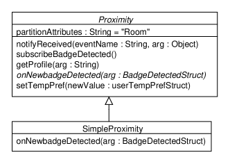
Abstract methods. For each input declared by a computational service, an abstract method is generated for receiving data. This abstract method is then implemented by the application developer. The class diagram in Figure 8 illustrates this concept. This class diagram uses italicized text for the Proximity class, which represents an abstract class, and onNewbadgeDetected() that represents abstract method. Then, it is implemented in the SimpleProximity class.
Listing 3 and 4 show Java code corresponding to the class diagram illustrated in Figure 8. From the badgeDetected input of the Proximity declaration in the architecture specification (Listing 2, lines 2-6), the onNewbadgeDetected() abstract method is generated (Listing 3, line 16). This method is implemented by the application developer. Listing 4 illustrates the implementation of onNewbadgeDetected(). It updates a user’s temperature preference and sets it using settempPref() method.
Concrete methods. The compilation of an architecture specification generates concrete methods to interact with other software component transparently. The generated concrete methods has the following two advantages:
-
1.
Abstracting heterogeneous interactions. To abstract heterogeneous interactions among software components, a compiler generates concrete methods that takes care of heterogeneous interactions. For instance, a computational service processes input data and produces refined data to its consumers. The input data is either notified by other component (i.e., publish/subscribe) or requested (i.e., request/response) by the service itself. Then, outputs are published. The concrete methods for these interaction modes are generated in an architecture framework. The lines 2 to 6 of Listing 2 illustrates these heterogeneous interactions. The Proximity service has two inputs: (1) It receives badgeDetect event (Listing 2, line 4). Our framework generates the subscribebadgeDetected() method to subscribe badgeDetected event (Listing 3, lines 8-12). Moreover, it generates the implementation of notifyReceived() method to receive the published events (Listing 3, lines 3-7). (2) It requests profile data (Listing 2, line 5). A sendcommand() method is generated to request data from other components (Listing 3, lines 13-15).
-
2.
Abstracting large scale. To address the scalable operations, a computational service annotates (1) its inputs with data interest, and (2) its placement in the region. Service placement and data interest jointly define a scope of a computational service to gather data. A generated architecture framework contains code that defines both data interest and its placement. For example, to get the badgeDetected event notification from the BadgeReader (Listing 2, line 4), the subscribebadgeDetected() method (Listing 3, lines 8-12) is generated in the Proximity class. This method defines the data interest of a service from where it receives data. The value of partitionAttribute (Listing 3, line 2), which comes from the architecture specification (Listing 2, line 6), defines the scope of receiving data. The above constructs are empowered by our choice of middleware, which is a variation of the one presented in [42], and enables delivery of data across logical scopes.
2.6 Specifying deployment concern
This concern describes information about a target deployment containing various attributes of devices (such as location, type, attached resources) and locations where computational services are executed in a deployment, described using SDL (discussed in Section 2.6.1). In order to map computational services to devices, we present a mapping technique that produces a mapping from a set of computational services to a set of devices (discussed in Section 2.6.2).
2.6.1 Srijan deployment language (SDL)
Figure 9 illustrates deployment-specific concepts (defined in the conceptual model Figure 2), specified using SDL. It includes device properties (such as name, type), regions where devices are placed, and resources that are hosted by devices. The resources () and regions () defined in a vocabulary become a set of values for certain attributes in SDL (see the underlined words in Listing 5). SDL can be described as . represents a set of devices. A device () can be defined as (). represents a set of device placements in terms of regions defined in a vocabulary. is a subset of resources defined in a vocabulary. represents a set of device type (e.g., JavaSE device, Android device) that is used to pick an appropriate device driver from a device driver repository. represents a set of two boolean values (true or false). The true value indicates a location of a device is not fixed, while the false value shows a fixed location. Listing 5 illustrates a deployment specification of the smart building application. This snippet describes a device called TemperatureMgmt-Device-1 with an attached TemperatureSensor and Heater, situated in building 15, floor 11, room 1, it is JavaSE enabled and non-mobile device.

Note that although individual listing of each device’s attributes appears tedious, i) we envision that this information can be extracted from inventory logs that are maintained for devices purchased and installed in systems, and ii) thanks to the separation between the deployment and functional concern in our approach, the same deployment specification can be re-used across IoT applications of a given application domain.
2.6.2 Mapping
This section presents our mapping algorithm that decides devices for a placement of computational services. It takes inputs as (1) a list of devices defined in a deployment specification (see listing 5) and (2) a list of computational services defined in an architecture specification (see listing 2). It produces a mapping of computational services to a set of devices.
We presents the mapping algorithm (see Algorithm 1) that comprises two steps. The first step (lines 4-9) constructs the two key-value data structures from a deployment specification. These two data structures are used in the second step. The second step (lines 10-20) selects devices randomly and allocates computational services to the selected devices101010 A mapping algorithm cognizant of heterogeneity, associated with devices of a target deployment, is a part of our future work. See future work for detail.. In order to give more clarity to readers, we describes these two steps in detail below.
The first step (Algorithm 1, lines 4-9) constructs two key-value data structures and from . The (line 6) is a key-value data structure where (e.g., Building, Floor, Room in the listing 5) is a key and (e.g., 15, 11, 1 in the listing 5) is a value. The (line 7) is a key-value data structure where is a key and (e.g., TemperatureMgmt-Device-1 in the listing 5) is a value. Once, these two data structures are constructed, we use them for the second step (lines 10-20).
The second step (Algorithm 1, lines 10-20) selects a device and allocates computational services to the selected device. To perform this task, the line 10 retrieves all keys (in our example Building, Floor, Room) of using function. For each computational service (e.g., Proximity, RoomAvgTemp, RoomController in listing 2), the selected key from the is compared with a partition value of a computational component (line 12). If the value match, the next step (lines 13-17) selects a device randomly and allocates a computational service to the selected device.
Computational complexity. The first step (Algorithm 1, lines 4-9) takes times, where is a number of devices and is a number of region pairs in each device specification. The second step (Algorithm 1, lines 10-20) takes times, where is a number of region names (e.g., building, floor, room for the building automation domain) defined in a vocabulary, is a number of computational services defined in an architecture specification, and is a number of region values specified in a deployment specification. Thus, total computational complexity of the mapping algorithm is .
2.7 Specifying platform concern
This concern describes software components that act as a translator between a hardware device and an application. Because these components are operating system-specific, the device developer implements them by hand. To aid the device developer, we generate a vocabulary framework to implement platform-specific device drivers. In the following section, we describe it in more detail.
2.7.1 Implementing device drivers
Leveraging the vocabulary specification, our system generates a vocabulary framework to aid the device developer. The vocabulary framework contains concrete classes and interfaces corresponding to resources defined in a vocabulary. A concrete class contains concrete methods for interacting with other software components and platform-specific device drivers. The interfaces are implemented by the device developer to write platform-specific device drivers. In order to enable interactions between concrete class and platform-specific device driver, we adopt the factory design pattern [25]. This pattern provides an interface for a concrete class to obtain an instance of different platform-specific device driver implementations without having to know what implementation the concrete class obtains. Since the platform-specific device driver implementation can be updated without necessitating any changes in code of concrete class, the factory pattern has advantages of encapsulation and code reuse. We illustrate this concept in the following paragraph with a BadgeReader example.
The class diagram in Figure 10 illustrates the concrete class BadgeReader, the interface IBadgeReader, and the associations between them through the factory class BadgeReaderFactory. The two abstract methods of the IBadgeReader interface (Listing 8, lines 1-4) are implemented in the AndroidBadgeReader class (Listing 9, lines 1-10). The platform-specific implementation is accessed through the BadgeReaderFactory class (Listing 7, lines 1-10). The BadgeReaderFactory class returns an instance of platform-specific implementations according to request by the concrete method registerBadgeReader() in the BadgeReader class (Listing 6, lines 12-15). In the following, we describe this class diagram with code snippet.
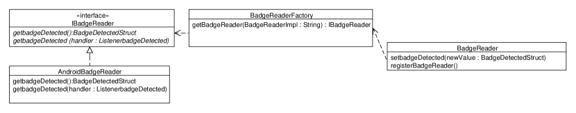
Concrete class. For each resource declared in a vocabulary specification, a concrete class is generated. This class contains concrete methods for interacting with other components transparently (similar to discussed in Section 2.5.2) and for interacting with platform-specific implementations. For example, the BadgeReader (Listing 6, lines 1-16) class is generated from the BadgeReader declaration (Listing 1, lines 14-15). The generated class contains the registerBadgeReader() method (Listing 6, lines 12-15). This method first obtains a reference of one (in our example Android) of platform-specific implementations, then uses that reference to create an object of that device-specific type (Listing 6, line 13). This reference is used to disseminate badgedetect event (Listing 6, lines 6-11).
Interfaces. For each resource declared in a vocabulary specification, interfaces are generated. Each interface contains synchronous and asynchronous abstract methods corresponding to a resource declaration. These methods are implemented by the device developer to write device-specific drivers. For example, our development system generates a vocabulary framework that contains the interface IBadgeReader (Listing 8, lines 1-4) corresponding to the BadgeReader (Listing 1, lines 14-17) declaration in the vocabulary specification. The device developer programs Android-specific implementations in the AndroidBadgeReader class by implementing the methods getbadgeDetected() and getbadgeDetected(handler) of the generated interface IBaderReader (Listing 9, lines 1-10).
2.8 Handling evolution
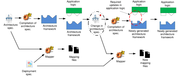
Evolution is an important aspect in IoT application development where resources and computational services are added, removed, or extended. To deal with these changes, we separate IoT application development into different concerns and allow an iterative development for these concerns. This iterative development requires only a change in evolved specification and reusing dependent specifications/implementation in compilation process, thus reducing effort to handle evolution, similar to the work in [12].
Figure 11 illustrates evolution in the functional concern. It could be addition, removal, or extension of computational services. A change in an architecture specification requires recompilation of it. The recompilation generates a new architecture framework and preserves the previously written application logic. This requires changes in the existing application logic implementations manually and re-compilation of the architecture specification to generate new mapping files that replaces old mapping files. We now review main evolution cases in each development concern and how our approach handles them.
Changing functionality. It refers to a change in behaviors of an application. For example, while an application might be initially defined to switch on an air-conditioner when a temperature of room is greater than , a new functionality might be to open a window. This case requires to write a new architecture specification and application logic.
Adding a new computational service. It refers to the addition of a new computational service in an architecture specification. The application developer implements the application logic of the newly added computational services.
Removing a computational service. It refers to the removal of an existing computation service from an architecture specification. The application developer has to manually remove application logic files of the removed computational service.
Adding a new input source. A new input of a computational service, represented as consume keyword, can be added. The application developer implements a generated abstract method corresponding to a new input in application logic files.
Removing a input source. An input can be removed from a computational service. In this case, the abstract method that implements the application logic becomes dead in application logic files. The IDE automatically reports errors. The application developer has to remove this dead abstract method manually.
Removing an output or command. An output (generate keyword) or command (command keyword) can be removed from an architecture specification. In this case code, which deals with output or command, becomes dead in application logic files. The application developer has to manually remove dead code.
3 Components of IoTSuite
In the following, we demonstrate the application development process, mentioned in Section 2.3, using IoTSuite111111An open source version, targeting on Android- and JavaSE -enabled devices and MQTT middleware, is available on: https://github.com/pankeshlinux/IoTSuite/wiki – a suite of tools, which is composed of different components, mentioned below, at each phase of application development that stakeholders can use.
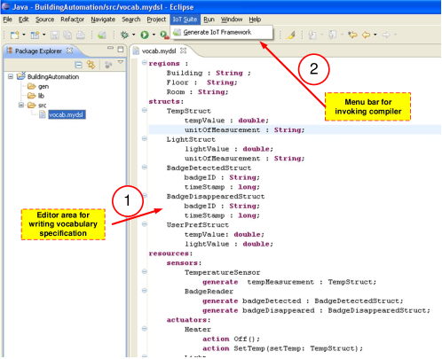
Editor. It helps stakeholders to write high-level specifications, including vocabulary, architecture, and deployment specification with the facilities of syntax coloring and syntax error reporting. We use Xtext121212http://www.eclipse.org/Xtext/ for a full fledged editor support, similar to work in [4]. The Xtext is a framework for a development of domain-specific languages, and provides an editor with syntax coloring by writing Xtext grammar.
We take an example of building automation domain vocabulary to demonstrate an editor support provided by IoTSuite, illustrated in Figure 12. The zone shows the editor, where the domain expert writes a domain vocabulary. The zone shows the menu bar, where the domain expert invokes the compiler for vocabulary to generate a framework, a customized architecture grammar, and deployment grammar.
Compiler. The compiler parses high-level specifications and translates them into code that can be used by other components in the system. The parser module of compiler is implemented using ANTLR131313http://www.antlr.org/, a well-known parser generator that creates parser files from grammar descriptions. The code generator module of compiler manages a repository of plug-ins. Each plug-in, defined as template files, is specific to a target implementation language (e.g., Java, Python). The key advantage of it is that it simplifies an implementation of a new code generator for a target implementation. The plug-ins are implemented using StringTemplate Engine,141414http://www.stringtemplate.org/ a Java template engine for generating source code or any other formatted text output. We build two compilers to aid stakeholders shown in Figure 3. (1) compiler for a vocabulary specification, and (2) compiler for an architecture specification. The current version of these compilers generate frameworks, compatible with Eclipse IDE.
Mapper. The mapper produces a mapping from a set of computational services to a set of devices. Figure 13 illustrates the architecture of the mapper component. The parser converts high-level specifications into appropriate data structures that can be used by a mapping algorithm. The mapping algorithm produces mapping decisions into appropriate data structures. The code generator consumes the data structures and generates mapping files. Our current implementation of the mapper randomly maps computational services to a set of devices. However, due to generality of our architecture, more sophisticated mapping algorithm can be plugged into the mapper.

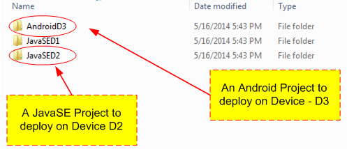
Linker. It combines and packs code generated by various stages of compilation into packages that can be deployed on devices. The output of the linker is a set of platform-specific projects for devices, specified in the deployment specification. These projects are not binaries. They need to be compiled, which can be done by any device-specific compiler designed for the target platform. The current version of the linker generates Java source packages for Android and JavaSE platform. Figure 14 illustrates packages for 3 target devices (2 packages for JavaSE devices and 1 for Android device), which can be imported into Eclipse IDE.
Runtime system. The main responsibility of the runtime system is a distributed execution of IoT applications. It is composed of three parts: (1) middleware: It runs on each individual device and provides a support for executing distributed tasks. (2) wrapper: It plugs packages, generated by the linker module, and middleware. (3) support library: It separates packages, produced by the linker component, and underlying middleware by providing interfaces that are implemented by each wrapper. The integration of a new middleware into IoTSuite consists of an implementation of the following interfaces, specified by the support library, in the wrapper.
-
1.
publish(). It is an interface for publishing data from a sender. The definition of this interface contains: an event name (e.g., temperature), event data (e.g., a temperature value, Celsius), and publisher’s information such as location.
-
2.
subscribe(). It is an interface for receiving event notifications. An interest of events is expressed by sending a subscription request, which contains: a event name (e.g., temperature), information for filtering events such as regions of interest (e.g., a RoomAvgTemp component wants to receive events only from a current room), and subscriber’s information.
-
3.
command(). It is an interface for triggering an action of an actuator. A command contains: a command name (e.g., switch-on heater), command parameters (e.g., set temperature of heater to 30∘C), and a sender’s information.
-
4.
request-response(). It is an interface for requesting data from a requester. In reply, a receiver sends a response. A request contains a request name (e.g., give profile information), request parameters (e.g., give profile of person with identification 12), and information about the requester.
The current implementation of IoTSuite uses the MQTT151515http://mqtt.org/ middleware, which enables interactions among Android devices and JavaSE enabled devices.
4 Evaluation
The goal of this section is to describe how well the proposed approach addresses our aim in a quantitative manner. Unfortunately, the goal is very vague because quality measures are not well-defined and they do not provide a clear procedural method to evaluate development approaches in general. We explore development effort, which indicates effort required to create an application, that is vital for the productivity of stakeholders [12].
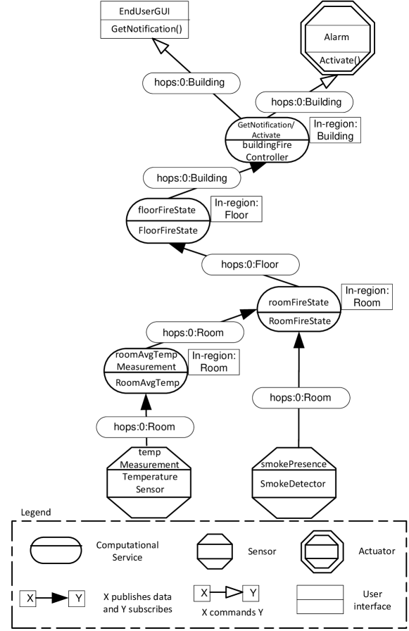
To evaluate our approach we consider two representative IoT applications: (1) the smart building application described in Section 1.1 and (2) a fire detection application, which aims to detect fire by analyzing data from smoke and temperature sensors. When fire occurs, residences are notified on their smart phones by an installed application. Additionally, residents of the building and neighborhood are informed through a set of alarms. Figure 15 shows the architecture of the fire detection application. A fire state is computed based on a current average temperature value and smoke presence by a local fire state service (i.e., roomFireState) deployed per room, then a state is sent to a service (i.e., floorFireState) deployed per floor, and finally a computational service (i.e., buildingFireController) decides whether alarms should be activated and users should be notified or not.
4.1 Development effort
In order to measure effort to develop an application, we evaluate a percentage of a total number of lines of code generated by our approach and effort to develop an application involving a large number of devices using our approach. we have implemented two IoT applications discussed in the previous Section using our approach. These applications are implemented independently. We did not reuse specifications and implementations of one application in other application. We deployed the two applications on 10 simulated devices running on top of a middleware that simulates network on a single PC dedicated to the evaluation.
We measured development effort using Eclipse EclEmma 2.2.1 plug-in. This tool counts actual Java statement as lines of code and does not consider blank lines or lines with comments. Our measurements reveal that more than 82% of the total number of lines of code is generated in two applications (see Table 2).
| Handwritten (lines of code) | Generated (lines of code) | % of Generated code | ||||||||
|---|---|---|---|---|---|---|---|---|---|---|
| Application Name | Vocab Spec. | Arch. Spec. | Deploy. Spec. | Device driver | App. logic | Mapping code | Archi. fram. | Vocab. fram. | Code coverage | |
| (devices=10) | ||||||||||
| Smart building | 41 | 28 | 81 | 98 | 131 | 561 | 408 | 757 | 81.99% | 92.22 |
| Fire detection | 27 | 21 | 81 | 53 | 72 | 528 | 292 | 476 | 83.61% | 90.38 |
The measure of lines of code is only useful if the generated code is actually executed. We measured code coverage of the generated programming frameworks of two applications (see Table 2) using the EclEmma161616http://www.eclemma.org/ Eclipse plug-in. Our measures show that more than 90% of generated code is actually executed, the other portion being error-handling code for errors that did not happen during the experiment. This high value indicates that most of the execution is spent in generated code and that, indeed, our approach reduces development effort by generating useful code.
The above experiment was conducted for 10 simulated devices. It does not demonstrate development effort using our approach for a large number of devices. Therefore, the primary aim of this experiment is to evaluate effort to develop an IoT application involving a large number of devices. In order to achieve the above aim, we have developed the smart building application on a set of simulated device running on top of the middleware dedicated to the evaluation. The assessments were conducted over an increasing number of devices. The first development effort assessment was conducted on 10 devices instrumented with heterogeneous sensors, actuators, storages, and user interfaces. In the next subsequent assessments, we kept increasing the number of devices equipped with sensors and actuators. In each assessment, we have measured lines of code to specify vocabulary, architecture, and deployment, application logic, and device drivers. Table 3 illustrates the assessment results containing a number of devices involved in the experiment and hand-written lines of code to develop the smart building application.
| Handwritten (lines of code) | |||||
|---|---|---|---|---|---|
| Number of devices | Vocab Spec. | Arch. Spec. | Deploy. Spec. | Device driver | App. logic |
| 10 | 41 | 28 | 81 | 98 | 131 |
| 34 | 41 | 28 | 273 | 98 | 131 |
| 50 | 41 | 28 | 401 | 98 | 131 |
| 62 | 41 | 28 | 497 | 98 | 131 |
| 86 | 41 | 28 | 689 | 98 | 131 |
| 110 | 41 | 28 | 881 | 98 | 131 |
| 200 | 41 | 28 | 1601 | 98 | 131 |
| 300 | 41 | 28 | 2401 | 98 | 131 |
| 350 | 41 | 28 | 2801 | 98 | 131 |
| 500 | 41 | 28 | 4001 | 98 | 131 |
In Table 3, we have noted the following two observations and their reasons:
-
1.
As the number of devices increases, lines of code for vocabulary and architecture specification, device drivers, and application logic remain constant for a deployment consisting a large number of devices. The reason is that our approach provides the ability to specify an application at a global level rather than individual nodes.
-
2.
As the number of devices increases, lines of code for a deployment specification increase. The reason is that the network manager specifies each device individually in the deployment specification. This is a limitation of SDL. Our future work will be to investigate how a deployment specification can be expressed in a concise and flexible way for a network with a large number of devices. We believe that the use of regular expressions is a possible technique to address this problem.
5 Related work
This Section focuses on existing works in literature that would address the research challenges discussed in Section 1.2. As stated earlier, while the application development life-cycle has been discussed in general in the software engineering domain, a similar structured approach is largely lacking in the IoT for the development of Sense-Computer-Control (SCC) [63, p. 97] applications. Consequently, in this Section we present existing approaches geared towards the IoT, but also its precursor fields of Pervasive Computing and Wireless Sensor Networking. These are mature fields, with several excellent surveys available on programming models [62, 43] and middleware [33].
We organize this Section based on the perspective of the system provided to the stakeholders by the various approaches. Section 5.1 presents the node-level programming approaches, where the developer has significant control over the actions of each device in the system, which comes at the cost of complexity. Section 5.2 summarizes approaches that aim to abstract the entire (sensing) system as a database on which one can run queries. Section 5.3 presents the evolution of these approaches to macroprogramming inspired by general-purpose programming languages, where abstractions are provided to specify high-level collaborative behaviors at the system-level while hiding low-level details from stakeholders. Section 5.4 then describes the macroprogramming approaches more grounded in model-driven development techniques, which aim to provide a cleaner separation of concerns during the application development process. We summarize all these approaches in Table LABEL:summarytable1.
5.1 Node-centric programming
In the following, we present systems that adopt the node-centric approach.
In the pervasive computing domain, Olympus [53] is a programming model on top of Gaia [54] – a distributed middleware infrastructure for pervasive environments. Stakeholders write a C++ program that consists of a high-level description about active space entities (including service, applications, devices, physical objects, and locations) and common active operations (e.g., switching devices on/, starting/stopping applications). The Olympus framework takes care of resolving high-level description based on properties specified by stakeholders. While this approach certainly simplifies the SCC application development involving heterogeneous devices, stakeholders have to write a lot of code to interface hardware and software components, as well as to interface software components and its interactions with a distributed system. This makes it tedious to develop applications involving a large number of devices.
The Context toolkit [17, 56] simplifies the context-aware application development on top of heterogeneous data sources by providing three architectural components, namely, widgets, interpreters, and aggregators. These components separate application semantics from platform-specific code. For example, an application does not have to be modified if an Android-specific sensor is used rather than a Sun SPOT sensor. It means stakeholders can treat a widget in a similar fashion and do not have to deal with differences among platform-specific code. Although context toolkit provides support for acquiring the context data from the heterogeneous sensors, it does not support actuation that is an essential part of IoT applications.
Henricksen et al. [32, 5] propose a middleware and a programming framework to gather, manage, and disseminate context to applications. This work introduces context modeling concepts, namely, context modeling languages, situation abstraction; and preference and branching models. This work presents a software engineering process that can be used in conjunction with the specified concepts. However, the clear separation of roles among the various stakeholders is missing. Moreover, this framework limits itself to context gathering applications, thus not providing the actuation support that is important for IoT application development.
Physical-Virtual mashup. As indicated by its name, it connects web services from both the physical and virtual world through visual constructs directly from web browsers. The embedded device runs tiny web servers [20] to answer HTTP queries from users for checking or changing the state of a device. For instance, users may want to see temperature of different places on map. Under such requirements, stakeholders can use the mashup to connect physical services such as temperature sensors and virtual services such as Google map. Many mashup prototypes have been developed that include both the physical and virtual services [8, 28, 13, 26, 30]. The mashup editor usually provides visual components representing web service and operations (such as add, filter) that stakeholders need to connect together to program an application. The framework takes care of resolving these visual components based on properties specified by stakeholders and produces code to interface software components and distributed system. The main advantage of this mashup approach is that any service, either physical or virtual, can be mashed-up if they follow the standards (e.g., REST). The Physical-Virtual mashup significantly lowers the barrier of the application development. However, stakeholders have to manage a potentially large graph for an application involving a large number of entities. This makes it difficult to develop applications containing a large number of entities.
5.2 Database approach
In TinyDB [39] and Cougar [68] systems, an SQL-like query is submitted to a WSN. On receiving a query, the system collects data from the individual device, filters it, and sends it to the base station. They provide a suitable interface for data collection in a network with a large number of devices. However, they do not offer much flexibility for introducing the application logic. For example, stakeholders require extensive modifications in the TinyDB parser and query engine to implement new query operators.
The work on SINA (Sensor Information Networking Architecture) [59] overcomes this limitation on specification of custom operators by introducing an imperative language with an SQL query. In SINA, stakeholders can embed a script written in Sensor Querying and Tasking Language (SQTL) [35] in the SQL query. By this hybrid approach, stakeholders can perform more collaborative tasks than what SQL in TinyDB and Cougar can describe.
The TinyDB, Cougar, and SINA systems are largely limited to homogeneous devices. The IrisNet (Internet-Scale Resource-Intensive Sensor Network) [27] allows stakeholders to query a large number of distributed heterogeneous devices. For example, Internet-connected PCs source sensor feeds and cooperate to answer queries. Similar to the other database approaches, stakeholders view the sensing network as a single unit that supports a high-level query in XML. This system provides a suitable interface for data collection from a large number of different types of devices. However, it does not offer flexibility for introducing the application logic, similar to TinyDB and Cougar.
Semantic Streams [67] allows stakeholders to pose a declarative query over semantic interpretations of sensor data. For example, instead of querying raw magnetometer data, stakeholders query whether a vehicle is a car or truck. The system infers this query and decides sensor data to use to infer the type of vehicle. The main benefit of using this system is that it allows people, with less technical background to query the network with heterogeneous devices. However, it presents a centralized approach for sensor data collection that limits its applicability for handling a network with a large number of devices.
Standardized protocols-based systems. A number of systems have been proposed to expose functionality of devices accessible through standardized protocols without having worry about the heterogeneity of underlying infrastructure [41]. They logically view sensing devices (e.g., motion sensor, temperature sensor, door and window sensor) as service providers for applications and provide abstractions usually through a set of services. We discuss these examples below.
Priyantha et al. [52] present an approach based on SOAP [9] to enable an evolutionary WSN where additional devices may be added after the initial deployment. To support such a system, this approach has adopted two features. (1) structured data: the data generated by sensing devices are represented in a XML format for that may be understood by any application. (2) structured functionality: the functionality of a sensing device is exposed by Web Service Description Language (WSDL) [15]. While this system addresses the evolution issue in a target deployment, the authors do not demonstrate the evolution scenarios such as a change in functionality of an application, technological advances in deployment devices.
A number of approaches based on REST [22] have been proposed to overcome the resource needs and complexity of SOAP-based web services for sensing and actuating devices. TinyREST [38] is one of first attempts to overcome these limitations. It uses the HTTP-based REST architecture to access a state of sensing and actuating devices. The TinyREST gateway maps the HTTP request to TinyOS messages and allows stakeholders to access sensing and actuating devices from their applications. The aim of this system is to make services available through standardized REST without having to worry about the heterogeneity of the underlying infrastructure; that said, it suffers from a centralized structure similar to TinySOA.
5.3 Macroprogramming languages
In the following, we present macroprogramming languages for IoT application development, which are grounded in traditional general purpose programming languages (whether imperative or functional) in order to provide developers with familiar abstractions.
Kairos [29] allows stakeholders to program an application in a Python-based language. The Kairos developers write a centralized program of a whole application. Then, the pre-processor divides the program into subprograms, and later its compiler compiles it into binary code containing code for accessing local and remote variables. Thus, this binary code allows stakeholders to program distributed sensor network applications. Although Kairos makes the development task easier for stakeholders, it targets homogeneous network where each device executes the same application.
Regiment [44] provides a high-level programming language based on Haskell to describe an application as a set of spatially distributed data streams. This system provides primitives that facilitate processing data, manipulating regions, and aggregating data across regions. The written program is compiled down to an intermediate token machine language that passes information over a spanning tree constructed across the WSN. In contrast to the database approaches, this approach provides greater flexibility to stakeholders when it comes to the application logic. However, the regiment program collects data to a single base station. It means that the flexibility for any-to-any device collaboration for reducing scale is difficult.
MacroLab [34] offers a vector programming abstraction similar to Matlab for applications involving both sensing and actuation. Stakeholders write a single program for an entire application using Matlab like operations such as addition, find, and max. The written macroprogram is passed to the MacroLab decomposer that generates multiple decompositions of the program. Each decomposition is analyzed by the cost analyzer that calculates the cost of each decomposition with respect to a cost profile (provided by stakeholders) of a target deployment. After choosing a best decomposition by the cost analyzer, it is passed to the compiler that converts the decomposition into a binary executable. The main benefit is that it offers flexibility of decomposing code according to cost profiles of the target platform. While this system certainly separates the deployment aspect and functionality of an application, this approach remains general purpose and provides little guidance to stakeholders about the application domain.
5.4 MDD approach
A number of model-driven approaches have been proposed to make IoT application development easy, described below.
PervML [58] allows stakeholders to specify pervasive applications at a high-level of abstraction using a set of models. This system raises the level of abstraction in program specification, and code generators produce code from these specifications. Nevertheless, it adopts generic UML notations to describe them, thus provides little guidance to stakeholders about the specific application domain. In addition to this, the main focus of this work is to address the heterogeneity associated with pervasive computing applications, and the consideration of a large number of devices in an application is missing. PervML integrates the mapping process at the deployment phase. However, stakeholders have to link the application code and configure device drivers manually. This manual work in the deployment phase is not suitable for IoT applications involving a large number of devices. Moreover, the separation between deployment and domain-specific features are missing. These limitations would restrict PervML to a certain level.
DiaSuite [12] is a suite of tools to develop pervasive computing applications. It combines design languages and covers application development life-cycle. The design language defines both a taxonomy of an application domain and an application architecture. Stakeholders define entities in a high-level manner to abstract heterogeneity. However, the consideration of a large number of devices in an application is largely missing. Moreover, the application deployment for a large number of heterogeneous devices using this approach is difficult because stakeholders require manual effort (e.g., mapping of computational services to devices).
ATaG [50], which is a WSN is a macroprogramming framework to develop SCC applications. ATaG presents a compilation framework that translates a program, containing abstract notations, into executable node-level programs. Moreover, it tackles the issue of scale reasonably well. The ATaG linker and mapper modules support the application deployment phase by producing device-specific code to result in a distributed software system collaboratively hosted by individual devices, thus providing automation at deployment phase. Nevertheless, the clear separation of roles among the various stakeholders in the application development, as well as the focus on heterogeneity among the constituent devices are largely missing. Moreover, the ATaG program notations remains general purpose and provides little guidance to stakeholders about the application domain.
RuleCaster [6, 7] introduces an engineering method to provide support for SCC applications, as well as evolutionary changes in the application development. The RuleCaster programming model is based on a logical partitioning of the network into spatial regions. The RuleCaster compiler takes as input the application program containing rules and a network model that describes device locations and its capabilities. Then, it maps processing tasks to devices. Similar to ATaG, this system handles the scale issue reasonably well by partitioning the network into several spatial regions. Moreover, it supports automation at the deployment phase by mapping computational components to devices. However, the clear separation of roles among the various stakeholders, support for application domain, as well as the focus on heterogeneity among the constituent devices are missing.
Pantagruel [19] is a visual approach dedicated to the development of home automation applications. The Pantagruel application development consists of three steps: (1) specification of taxonomy to define entities of the home automation domain (e.g., temperature sensor, alarm, door, smoke detector, etc.), (2) specification of rules to orchestrate these entities using the Pantagruel visual language, and (3) compilation of the taxonomy and orchestration rules to generate a programming framework. The novelty of this approach is that the orchestration rules are customized with respect to entities defined in the taxonomy. While this system reduces the requirement of having domain-specific knowledge for other stakeholders, the clear separation of different development concerns, support for large scale, automation both at the development and deployment phase are largely missing. These limitations make it difficult to use for IoT application development.
| Existing Approaches | Division of roles | Hetro. | Scale | Life-cycle phases | ||||
|---|---|---|---|---|---|---|---|---|
| Development phase | Deployment phase | Maintenance phase | ||||||
| ContextToolkit [17] (2001) | ||||||||
| Node-centric | Olympus [53] (2005) | |||||||
| Programming | Henricksen et al. [5] (2010) | |||||||
| Dominique et al. [28] (2010) | ||||||||
| TinyDB [39] (2000) | Not clear | |||||||
| IrisNet [27] (2000) | Not clear | |||||||
| Database | SINA [59] (2000) | Not clear | ||||||
| Approach | TinyREST [38] (2005) | |||||||
| Semantic Streams [67] (2006) | ||||||||
| Priyantha et al. [52] (2008) | ||||||||
| Macroprogramming | Kairos [29] (2005) | |||||||
| Languages | Regiment [44] (2007) | |||||||
| MacroLab [34] (2008) | ||||||||
| RuleCaster [7] (2007) | ||||||||
| Model-driven | Pantagruel [19] (2009) | |||||||
| Development | PervML [58] (2010) | |||||||
| DiaSuite [12] (2011) | ||||||||
| ATaG [50] (2011) | ||||||||
6 Conclusion
This paper presents a development methodology for IoT application development, based on techniques presented in the domains of sensor network macroprogramming and model-driven development. It separates IoT application development into different concerns and integrates a set of high-level languages to specify them. This approach is supported by automation techniques at different phases of IoT application development and allows an iterative development to handle evolutions in different concerns. Our evaluation based on two realistic IoT applications shows that our approach generates a significant percentage of the total application code, drastically reduces development effort for IoT applications involving a large number of devices. Our approach addresses the challenges discussed in Section 1.2 in the following manner:
Lack of division of roles. Our approach identifies roles of each stakeholder and separates them according to their skills. The clear identification of expectations and specialized skills of each stakeholder helps them to play their part effectively, thus promoting a suitable division of work among stakeholders involved in IoT application development.
Heterogeneity. SAL and SVL provide abstractions to specify different types of devices, as well as heterogeneous interaction modes in a high-level manner. Further, high-level specifications written using SAL and SVL are compiled to a programming framework that (1) abstracts heterogeneous interactions among software components and (2) aids the device developers to write code for different platform-specific implementations.
Scale. SAL allows the software designer to express his requirements in a compact manner regardless of the scale of a system. Moreover, it offers scope constructs to facilitate scalable operations within an application. They reduce scale by enabling hierarchical clustering in an application. To do so, these constructs group devices to form a cluster based on their spatial relationship (e.g., “devices are in room#1”). Within a cluster, a cluster head is placed to receive and process data from its cluster of interest. The grouping could be recursively applied to form a hierarchy of clusters. The scale issue is thus handled, thanks to the use of a middleware that supports logical scopes and regions.
Different life cycle phases. Our approach is supported by code generation, task-mapping, and linking techniques. These techniques together provide automation at different life cycle phases. At the development phase, the code generator produces (1) an architecture framework that allows the application developer to focus on the application logic by producing code that hide low-level interaction details and (2) a vocabulary framework to aid the device developer to implement platform-specific device drivers. At the deployment phase, the mapping and linking together produce device-specific code to result in a distributed software system collaboratively hosted by individual devices. To support maintenance phase, our approach separates IoT application development into different concerns and allows an iterative development, supported by the automation techniques.
7 Future work
This paper addresses the challenges, presented by the steps involved in IoT application development, and prepares a foundation for our future research work. Our future work will proceed in the following complementary directions, discussed below.
Mapping algorithms cognizant of heterogeneity. While the notion of region labels is able to reasonably tackle the issue of scale at an abstraction level, the problem of heterogeneity among the devices still remains. We will provide rich abstractions to express both the properties of the devices (e.g., processing and storage capacity, networks it is attached to, as well as monetary cost of hosting a computational service), as well as the requirements from stakeholders regarding the preferred placement of the computational services of the applications. These will then be used to guide the design of algorithms for efficient mapping (and possibly migration) of computational services on devices.
Developing concise notion for SDL. In the current version of SDL, the network manager is forced to specify the detail of each device individually. This approach works reasonably well in a target deployment with a small number of devices. However, it may be time-consuming and error-prone for a target deployment consisting of hundreds to thousands of devices. Our future work will be to investigate how the deployment specification can be expressed in a concise and flexible way for a network with a large number of device. We believe that the use of regular expressions is a possible technique to address this problem.
Testing support for IoT application development. Our near term future work will be to provide support for the testing phase. A key advantage of testing is that it emulates the execution of an application before deployment so as to identify possible conflicts, thus reducing application debugging effort. The support will be provided by integrating an open source simulator. This simulator will enable transparent testing of IoT applications in a simulated physical environment. Moreover, we expect to enable the simulation of a hybrid environment, combining both real and physical entities. Currently, we are investigating open source simulators for IoT applications. We see Siafu171717http://siafusimulator.org/ as a possible candidate due to its open source and thorough documentation.
Run-time adaptation in IoT applications. Even though our approach addresses the challenges posed by evolutionary changes in target deployments and application requirements, stakeholders have to still recompile the updated code. This is common practice in a single PC-based development environment, where recompilation is generally necessary to integrate changes. However, it would be very interesting to investigate how changes can be injected into the running application that would adapt itself accordingly. For instance, when a new device is added into the target deployment, an IoT application can autonomously include a new device and assign a task that contributes to the execution of the currently running application.
Acknowledgment
This research work is partially done at University of Paris and French National Institute for Research in Computer Science & Automation (INRIA), France during Pankesh Patel’s Ph.D. thesis. The authors would gratefully like to thank researchers at Inria, Dimitris Soukaras, and the reviewers for their helpful comments and suggestions.
References
- Andrews [1991] Andrews, G.R., 1991. Paradigms for process interaction in distributed programs. ACM Computing Surveys (CSUR) 23, pp. 49–90.
- Atzori et al. [2010] Atzori, L., Iera, A., Morabito, G., 2010. The Internet of Things: A Survey. Computer Networks 54, 2787–2805.
- Berson [1996] Berson, A., 1996. Client/server architecture (2. ed.). McGraw-Hill.
- Bertran et al. [2012] Bertran, B., Bruneau, J., Cassou, D., Loriant, N., Balland, E., Consel, C., 2012. DiaSuite: a tool suite to develop sense/compute/control applications. Science of Computer Programming .
- Bettini et al. [2010] Bettini, C., Brdiczka, O., Henricksen, K., Indulska, J., Nicklas, D., Ranganathan, A., Riboni, D., 2010. A survey of context modelling and reasoning techniques. Pervasive and Mobile Computing 6, 161–180.
- Bischoff and Kortuem [2006] Bischoff, U., Kortuem, G., 2006. Rulecaster: A macroprogramming system for sensor networks, in: Proceedings OOPSLA Workshop on Building Software for Sensor Networks.
- Bischoff and Kortuem [2007] Bischoff, U., Kortuem, G., 2007. Life cycle support for sensor network applications, in: Proceedings of the 2nd international workshop on Middleware for sensor networks, ACM. pp. 1–6.
- Blackstock and Lea [2012] Blackstock, M., Lea, R., 2012. WoTKit: a lightweight toolkit for the web of things, in: Proceedings of the Third International Workshop on the Web of Things, ACM. p. 3.
- Box et al. [2000] Box, D., Ehnebuske, D., Kakivaya, G., Layman, A., Mendelsohn, N., Nielsen, H.F., Thatte, S., Winer, D., 2000. Simple object access protocol (SOAP) 1.1.
- CASAGRAS [2008] CASAGRAS, 2008. RFID and inclusive Model for the Internet of Things Available: http://www.grifs-project.eu/data/File/CASAGRAS%20FinalReport%20(2).pdf. Technical Report. EU Framework 7 Project.
- Cassou et al. [2009] Cassou, D., Bertran, B., Loriant, N., Consel, C., et al., 2009. A generative programming approach to developing pervasive computing systems, in: GPCE’09: Proceedings of the 8th international conference on Generative programming and component engineering, pp. 137–146.
- Cassou et al. [2011] Cassou, D., Bruneau, J., Consel, C., Balland, E., 2011. Towards a Tool-based Development Methodology for Pervasive Computing Applications. IEEE Transactions on Software Engineering .
- Castellani et al. [2012] Castellani, A.P., Dissegna, M., Bui, N., Zorzi, M., 2012. WebIoT: A web application framework for the internet of things, in: Wireless Communications and Networking Conference Workshops (WCNCW),, IEEE. pp. 202–207.
- Chen et al. [2012] Chen, C., Helal, S., de Deugd, S., Smith, A., Chang, C.K., 2012. Toward a collaboration model for smart spaces, in: SESENA, pp. 37–42.
- Chinnici et al. [2007] Chinnici, R., Moreau, J.J., Ryman, A., Weerawarana, S., 2007. Web services description language (WSDL) version 2.0 part 1: Core language. W3C Recommendation 26.
- Costa et al. [2007] Costa, P., Mottola, L., Murphy, A., Picco, G., 2007. Programming wireless sensor networks with the teeny lime middleware. Middleware 2007 , 429–449.
- Dey et al. [2001] Dey, A., Abowd, G., Salber, D., 2001. A conceptual framework and a toolkit for supporting the rapid prototyping of context-aware applications. Human–Computer Interaction 16, 97–166.
- Doddapaneni et al. [2012] Doddapaneni, K., Ever, E., Gemikonakli, O., Malavolta, I., Mostarda, L., Muccini, H., 2012. A model-driven engineering framework for architecting and analysing wireless sensor networks, in: Third International Workshop on Software Engineering for Sensor Network Applications (SESENA), IEEE. pp. 1–7.
- Drey et al. [2009] Drey, Z., Mercadal, J., Consel, C., 2009. A taxonomy-driven approach to visually prototyping pervasive computing applications, in: Domain-Specific Languages, Springer. pp. 78–99.
- Duquennoy et al. [2009] Duquennoy, S., Grimaud, G., Vandewalle, J.J., 2009. The Web of Things: interconnecting devices with high usability and performance, in: International Conference on Embedded Software and Systems (ICESS)., pp. 323–330.
- Eugster et al. [2003] Eugster, P., Felber, P., Guerraoui, R., Kermarrec, A., 2003. The many faces of publish/subscribe. ACM Computing Surveys (CSUR) 35, 114–131.
- Fielding [2000] Fielding, R.T., 2000. Architectural styles and the design of network-based software architectures. Ph.D. thesis. University of California.
- Fowler [1996] Fowler, M., 1996. Analysis Patterns: Reusable Object Models. Addison-Wesley Longman, Amsterdam.
- France and Rumpe [2007] France, R., Rumpe, B., 2007. Model-driven development of complex software: A research roadmap, in: 2007 Future of Software Engineering, IEEE Computer Society. pp. 37–54.
- Gamma et al. [1995] Gamma, E., Helm, R., Johnson, R., Vlissides, J., 1995. Design patterns: elements of reusable object-oriented software. Addison-Wesley Longman Publishing Co., Inc.
- Ghidini et al. [2012] Ghidini, G., Das, S.K., Gupta, V., 2012. Fuseviz: A framework for web-based data fusion and visualization in smart environments, in: IEEE 9th International Conference on Mobile Adhoc and Sensor Systems (MASS), IEEE. pp. 468–472.
- Gibbons et al. [2003] Gibbons, P.B., Karp, B., Ke, Y., Nath, S., Seshan, S., 2003. Irisnet: An architecture for a worldwide sensor web. Pervasive Computing, IEEE 2, 22–33.
- Guinard et al. [2010] Guinard, D., Trifa, V., Wilde, E., 2010. A resource oriented architecture for the web of things, in: Internet of Things (IOT),, IEEE. pp. 1–8.
- Gummadi et al. [2005] Gummadi, R., Gnawali, O., Govindan, R., 2005. Macro-programming wireless sensor networks using kairos. Distributed Computing in Sensor Systems , 466–466.
- Gupta et al. [2010] Gupta, V., Udupi, P., Poursohi, A., 2010. Early lessons from building sensor. network: an open data exchange for the web of things, in: 8th IEEE International Conference on Pervasive Computing and Communications Workshops, pp. 738–744.
- Haller [2010] Haller, S., 2010. The Things in the Internet of Things. Poster at the (IoT 2010). Tokyo, Japan, November .
- Henricksen and Indulska [2006] Henricksen, K., Indulska, J., 2006. Developing context-aware pervasive computing applications: Models and approach. Pervasive and Mobile Computing 2, 37–64.
- Henricksen and Robinson [2006] Henricksen, K., Robinson, R., 2006. A survey of middleware for sensor networks: state-of-the-art and future directions, in: Proceedings of the international workshop on Middleware for sensor networks, ACM. pp. 60–65.
- Hnat et al. [2008] Hnat, T.W., Sookoor, T.I., Hooimeijer, P., Weimer, W., Whitehouse, K., 2008. Macrolab: a vector-based macroprogramming framework for cyber-physical systems, in: Proceedings of the 6th ACM conference on Embedded network sensor systems, ACM. pp. 225–238.
- Jaikaeo et al. [2000] Jaikaeo, C., Srisathapornphat, C., Shen, C.C., 2000. Querying and tasking in sensor networks, in: AeroSense 2000, International Society for Optics and Photonics. pp. 184–194.
- Kruchten [1995] Kruchten, P., 1995. The 4+ 1 view model of architecture. Software, IEEE 12, 42–50.
- Kulkarni and Reddy [2003] Kulkarni, V., Reddy, S., 2003. Separation of concerns in model-driven development. Software, IEEE 20, 64–69.
- Luckenbach et al. [2005] Luckenbach, T., Gober, P., Arbanowski, S., Kotsopoulos, A., Kim, K., 2005. TinyREST-a protocol for integrating sensor networks into the internet, in: Proc. of REALWSN, Citeseer.
- Madden et al. [2005] Madden, S., Franklin, M., Hellerstein, J., Hong, W., 2005. TinyDB: An acquisitional query processing system for sensor networks. ACM Transactions on Database Systems (TODS) 30, 122–173.
- Mellor et al. [2003] Mellor, S.J., Clark, T., Futagami, T., 2003. Model-driven development: guest editors’ introduction. IEEE software 20, 14–18.
- Mohamed and Al-Jaroodi [2011] Mohamed, N., Al-Jaroodi, J., 2011. A survey on service-oriented middleware for wireless sensor networks. Service Oriented Computing and Applications 5, 71–85.
- Mottola et al. [2007] Mottola, L., Pathak, A., Bakshi, A., Prasanna, V., Picco, G., 2007. Enabling scope-based interactions in sensor network macroprogramming, in: Mobile Adhoc and Sensor Systems, 2007. MASS 2007. IEEE Internatonal Conference on, IEEE. pp. 1–9.
- Mottola and Picco [2011] Mottola, L., Picco, G., 2011. Programming wireless sensor networks: Fundamental concepts and state of the art. ACM Computing Surveys (CSUR) 43, 19.
- Newton et al. [2007] Newton, R., Morrisett, G., Welsh, M., 2007. The regiment macroprogramming system, in: Proceedings of the 6th international conference on Information processing in sensor networks, ACM. pp. 489–498.
- Patel [2013] Patel, P., 2013. Enabling High-Level Application Development for the Internet of Things. These. Université Pierre et Marie Curie - Paris VI. URL: http://tel.archives-ouvertes.fr/tel-00927150/PDF/these.pdf.
- Patel et al. [2014] Patel, P., Morin, B., Chaudhary, S., 2014. A model-driven development framework for developing sense-compute-control applications, in: Proceedings of the 1st International Workshop on Modern Software Engineering Methods for Industrial Automation, ACM, New York, NY, USA. pp. 52–61.
- Patel et al. [2013] Patel, P., Pathak, A., Cassou, D., Issarny, V., 2013. Enabling High-Level Application Development in the Internet of Things, in: 4th International Conference on Sensor Systems and Software, Lucca, Italy.
- Patel et al. [2011] Patel, P., Pathak, A., Teixeira, T., Issarny, V., 2011. Towards application development for the Internet of Things, in: Proceedings of the 8th Middleware Doctoral Symposium, ACM. p. 5.
- Pathak et al. [2007] Pathak, A., Mottola, L., Bakshi, A., Prasanna, V., Picco, G., 2007. A compilation framework for macroprogramming networked sensors. Distributed Computing in Sensor Systems , 189–204.
- Pathak and Prasanna [2011] Pathak, A., Prasanna, V., 2011. High-level application development for sensor networks: Data-driven approach. Theoretical Aspects of Distributed Computing in Sensor Networks , 865–891.
- Picco [2010] Picco, G., 2010. Software engineering and wireless sensor networks: happy marriage or consensual divorce?, in: Proceedings of the FSE/SDP workshop on Future of software engineering research, ACM. pp. 283–286.
- Priyantha et al. [2008] Priyantha, N.B., Kansal, A., Goraczko, M., Zhao, F., 2008. Tiny web services: design and implementation of interoperable and evolvable sensor networks, in: Proceedings of the 6th ACM conference on Embedded network sensor systems, ACM, New York, NY, USA. pp. 253–266.
- Ranganathan et al. [2005] Ranganathan, A., Chetan, S., Al-Muhtadi, J., Campbell, R., Mickunas, M., 2005. Olympus: A high-level programming model for pervasive computing environments, in: Third IEEE International Conference on Pervasive Computing and Communications(PerCom)., pp. 7–16.
- Román et al. [2002] Román, M., Hess, C., Cerqueira, R., Ranganathan, A., Campbell, R.H., Nahrstedt, K., 2002. Gaia: a middleware platform for active spaces. ACM SIGMOBILE Mobile Computing and Communications Review 6, 65–67.
- de Saint-Exupery [2009] de Saint-Exupery, A., 2009. Internet of things, strategic research roadmap.
- Salber et al. [1999] Salber, D., Dey, A.K., Abowd, G.D., 1999. The context toolkit: aiding the development of context-enabled applications, in: Proceedings of the SIGCHI conference on Human factors in computing systems: the CHI is the limit, ACM, New York, NY, USA. pp. 434–441.
- Schmidt [2006] Schmidt, D.C., 2006. Guest Editor’s Introduction: Model-Driven Engineering. IEEE Computer Society 39, 25–31. URL: http://www.cs.wustl.edu/~schmidt/GEI.pdf.
- Serral et al. [2010] Serral, E., Valderas, P., Pelechano, V., 2010. Towards the model driven development of context-aware pervasive systems. Pervasive and Mobile Computing 6, 254–280.
- Shen et al. [2001] Shen, C., Srisathapornphat, C., Jaikaeo, C., 2001. Sensor information networking architecture and applications. Personal communications, IEEE 8, 52–59.
- Sommerville [2010] Sommerville, I., 2010. Software Engineering. 9 ed., Addison-Wesley, Harlow, England.
- Soukaras et al. [2015] Soukaras, D., Patel, P., Song, H., Chaudhary, S., 2015. IoTSuite : A ToolSuite for Prototyping Internet of Things Applications. The 4th International Workshop on Computing and Networking for Internet of Things (ComNet-IoT), co-located with 16th International Conference on Distributed Computing and Networking (ICDCN), 2015 .
- Sugihara and Gupta [2008] Sugihara, R., Gupta, R., 2008. Programming models for sensor networks: A survey. ACM Transactions on Sensor Networks (TOSN) 4, 8.
- Taylor et al. [2009] Taylor, R., Medvidovic, N., Dashofy, E., 2009. Software architecture: foundations, theory, and practice. Wiley Publishing.
- Tubaishat and Madria [2003] Tubaishat, M., Madria, S., 2003. Sensor networks: an overview. Potentials, IEEE 22, 20–23.
- Vasseur and Dunkels [2010] Vasseur, J.P., Dunkels, A., 2010. Interconnecting smart objects with IP: The next internet. Morgan Kaufmann, San Francisco, CA, USA.
- Whitehouse et al. [2004] Whitehouse, K., Sharp, C., Brewer, E., Culler, D., 2004. Hood: a neighborhood abstraction for sensor networks, in: Proceedings of the 2nd international conference on Mobile systems, applications, and services, ACM. pp. 99–110.
- Whitehouse et al. [2006] Whitehouse, K., Zhao, F., Liu, J., 2006. Semantic streams: a framework for composable semantic interpretation of sensor data, in: Proceedings of the Third European conference on Wireless Sensor Networks, Springer-Verlag, Berlin, Heidelberg. pp. 5–20.
- Yao and Gehrke [2002] Yao, Y., Gehrke, J., 2002. The cougar approach to in-network query processing in sensor networks. SIGMOD Rec. 31, 9–18.