Quantized Transport for a Skyrmion Moving on a Two-Dimensional Periodic Substrate
Abstract
We examine the dynamics of a skyrmion moving over a two-dimensional periodic substrate utilizing simulations of a particle-based skyrmion model. We specifically examine the role of the non-dissipative Magnus term on the driven motion and the resulting skyrmion velocity-force curves. In the overdamped limit, there is a depinning transition into a sliding state in which the skyrmion moves in the same direction as the external drive. When there is a finite Magnus component in the equation of motion, a skyrmion in the absence of a substrate moves at an angle with respect to the direction of the external driving force. When a periodic substrate is added, the direction of motion or Hall angle of the skyrmion is dependent on the amplitude of the external drive, only approaching the substrate-free limit for higher drives. Due to the underlying symmetry of the substrate the direction of skyrmion motion does not change continuously as a function of drive, but rather forms a series of discrete steps corresponding to integer or rational ratios of the velocity components perpendicular () and parallel () to the external drive direction: , where and are integers. The skyrmion passes through a series of directional locking phases in which the motion is locked to certain symmetry directions of the substrate for fixed intervals of the drive amplitude. Within a given directionally locked phase, the Hall angle remains constant and the skyrmion moves in an orderly fashion through the sample. Signatures of the transitions into and out of these locked phases take the form of pronounced cusps in the skyrmion velocity versus force curves, as well as regions of negative differential mobility in which the net skyrmion velocity decreases with increasing external driving force. The number of steps in the transport curve increases when the relative strength of the Magnus term is increased. We also observe an overshoot phenomena in the directional locking, where the skyrmion motion can lock to a Hall angle greater than the clean limit value and then jump back to the lower value at higher drives. The skyrmion-substrate interactions can also produce a skyrmion acceleration effect in which, due to the non-dissipative dynamics, the skyrmion velocity exceeds the value expected to be produced by the external drive. We find that these effects are robust for different types of periodic substrates. Using a simple model for a skyrmion interacting with a single pinning site, we can capture the behavior of the change in the Hall angle with increasing external drive. When the skyrmion moves through the pinning site, its trajectory exhibits a side step phenomenon since the Magnus term induces a curvature in the skyrmion orbit. As the drive increases, this curvature is reduced and the side step effect is also reduced. Increasing the strength of the Magnus term reduces the range of impact parameters over which the skyrmion can be captured by a pinning site, which is one of the reasons that strong Magnus force effects reduce the pinning in skyrmion systems.
pacs:
75.47.Np,75.30.Kz,75.10.Hk,75.25.-j,75.75.-cI Introduction
Skyrmions were predicted to occur in certain magnetic systems 1 and were subsequently experimentally identified in the chiral magnet MnSi 2 . Since this initial discovery there has been tremendous growth in the field as an increasing number of materials have been found that can support a skyrmion phase 3 ; 4 ; 5 ; 6 ; 7 ; 8 ; 9 ; 10 . There are also numerous proposals on how to stabilize skyrmion states by utilizing different materials properties or bilayers 11 ; 12 ; 13 ; 14 . Direct imaging of skyrmions with Lorentz microscopy 3 ; 4 ; 5 ; 7 ; 10 and other techniques 8 ; 15 ; 16 show that the skyrmions form a triangular lattice and have particle-like properties similar to vortices in type-II superconductors 38 . As an external magnetic field is increased, skyrmions emerge from a spiral state and their density initially increases and then decreases with field until the sample enters a uniform ferromagnetic state 2 ; 3 ; 9 . In bulk samples, skyrmions form three-dimensional (3D) line objects and occur in a limited range of fields and temperatures 2 ; 16 , while for thin samples the skyrmions exhibit two-dimensional (2D) properties and are stable over a much larger range of fields and temperatures extending close to room temperature 4 ; 5 ; 6 ; 7 . Skyrmions can be set into motion through the application of an external current 17 ; 7 ; 18 ; 19 ; 10 , and it has been shown that there is a critical current above which the skyrmions depin into a sliding state 18 ; 19 ; 21 ; 23 ; 24 ; 25 ; 26 ; 27 . Skyrmion motion can be directly observed with Lorentz microscopy 7 ; 10 or deduced from changes in the transport properties, permitting the construction of effective skyrmion velocity versus applied force curves that show that the skyrmion velocity increases with increasing current 19 . Other methods to move skyrmions include the use of temperature gradients 28 ; 29 ; 30 ; 31 ; 32 , electric fields 33 ; 34 , and coupling to a magnetic tip 15 .
From an applications standpoint, skyrmions are attracting attention due to their potential use in racetrack memory devices where they would play a role similar to that of magnetic domain walls 35 ; 36 ; 37 . Skyrmions have several advantages over domain walls due to their size and the fact that the current needed to depin a skyrmion can be orders of magnitude smaller than that needed to move domain walls 19 ; 35 . It has been experimentally demonstrated that individual skyrmions can be created or annihilated with a magnetic tip, indicating that it is feasible to read and write skyrmions 16 . Developing applications of skyrmions will require an understanding of how skyrmions interact with and move along tailored landscapes, so examining skyrmion dynamics on periodic substrates is an important step in this direction.
Skyrmions have many similarities to vortices in type-II superconductors, such as the effective skyrmion-skyrmion interaction, which is repulsive and favors triangular ordering, and the fact that both skyrmions and vortices can be driven by an external current. In the presence of quenched disorder, skyrmions exhibit pinning-depinning transitions 37 , as observed in experiments 19 and simulations 21 ; 23 ; 24 ; 25 ; 26 , and these are similar to the depinning transitions observed for vortices in type-II superconductors 38 ; 39 ; 40 ; 41 . There are important differences between the two systems, particularly the dominant role that non-dissipative effects can take in skyrmion motion. For superconducting vortices, non-dissipative effects such as a Magnus force are typically small, permitting the system to be effectively described as obeying overdamped dynamics 38 ; 40 . In a skyrmion system, by contrast, the Magnus term can strongly affect how the skyrmions interact with pinning sites and how they move under an external drive 18 ; 21 ; 23 . Numerical simulations using continuum and particle-based models for skyrmions interacting with pinning have shown that the Magnus term reduces the effective pinning in the system by creating a velocity component that is perpendicular to the force induced by a pinning site 18 ; 21 ; 23 ; 24 ; 26 . As a result, skyrmions have a tendency to swing around the edge of a pinning site and escape, while for overdamped systems a particle moves toward the center of a pinning site and is much more likely to be pinned.
Relatively little is known about how particles with a strong Magnus term move over a periodic substrate, and skyrmions are an ideal system to study such effects. In certain limits, a skyrmion can be effectively modeled as a point-like particle utilizing an equation of motion 23 ; 24 derived from Thiele’s equation 42 . Comparison between continuum-based models and particle-based models of skyrmions moving in the presence of pinning have shown good agreement 23 ; 24 . In this work we examine the dynamics of a skyrmion moving over a square periodic substrate using a particle-based description given in Section II. We specifically examine the effect of changing the importance of the Magnus term relative to that of the damping term. Despite the apparent simplicity of this system, we show in Section III that the Magnus term can induce a remarkably rich variety of dynamical behaviors that are absent in the overdamped limit. We find that the Hall angle for the skyrmion motion is dependent on the external drive amplitude and approaches the substrate-free limit only at higher drives. Since the skyrmion is moving over a periodic substrate, as the Hall angle changes the motion becomes locked to specific symmetry directions of the substrate, producing a series of steps in the transport curves corresponding to integer and rational fractional ratios of the skyrmion velocity in the directions parallel and perpendicular to the drive direction. At the transitions into the different directional locking phases, the skyrmion velocity exhibits a pronounced cusp accompanied by negative differential mobility in which the skyrmion velocity decreases with increasing external driving force. We map the extent of the locking phase as a function of the external drive and the ratio of the Magnus and dissipative terms, and find a rich structure of integer and fractional locking effects. We also describe a speedup effect for skyrmions interacting with a substrate where the skyrmion velocity can be higher than the external drive. This effect is most prominent just above depinning and is caused by the Magnus term; it is absent in the overdamped case. In Section IV we consider a skyrmion scattering from a single pinning site for varied impact parameters to show how the Hall angle is reduced by the pinning due to a side-step phenomenon where the skyrmion trajectory is shifted by the Magnus term as the skyrmion moves through the pinning site. For increasing drive amplitude, the skyrmion trajectories become less curved and the size of the side step is reduced, so that the Hall angle approaches the clean limit for higher drives. Our results for the speedup effect and side steps are in agreement with recent theoretical and computational studies by Müller and Rosch, who considered a single skyrmion interacting with a defect site 27 . In that work, the pinning potential is of a different form than the pinning sites we consider; however, the consistency of the two studies indicates that the Hall angle dependence on external drive and the speedup phenomenon are generic features of skyrmions interacting with pinning.
There are other examples of particles moving over ordered substrates, such as vortices in type-II superconductors with periodic pinning arrays 43 ; 44 ; 45 or colloids placed on optically created periodic substrates 47 ; 48 . In these systems the dynamics is overdamped; however, there can be directional locking effects in which the particles preferentially move along symmetry directions of the underlying substrate as the direction of drive is rotated with respect to the substrate lattice 51 ; 52 ; 53 ; 54 ; 55 ; 56 ; 57 ; 58 . Such directional locking effects can be exploited to perform particle separation in colloidal systems by setting up a system in which one particle species locks to the substrate while the second species does not, causing the two species to move at an angle with each other 53 ; 54 . The direction of motion of the locked particles undergoes a series of steps as a function of the effective angle of drive with respect to the substrate. The steps are centered at integer and rational ratios of the angle of drive and form a devil’s staircase structure 52 ; 53 ; 54 ; 56 ; 57 ; 59 ; 60 . In the skyrmion system, we observe directional locking effects when the direction of external drive is fixed with respect to the substrate and the drive amplitude is varied. The directional locking and transitions into the locking states in the skyrmion system exhibit a number of features that have not been observed in overdamped systems, such as an overshoot effect in the locking direction and negative differential mobility at the locking transition. The steps in the transport response are also distinct from the Shapiro steps found in systems that can be effectively described as a particle moving over a periodic substrate under superimposed ac and dc drives 61 ; 62 . In the system we consider in this work, there is no imposed ac drive.
II Simulation and System
We consider a skyrmion moving over a 2D square periodic substrate and utilize a particle-based description of the skyrmion from a recently developed equation of motion for skyrmions 23 ; 24 . The dynamics of the skyrmion is obtained by integrating the equation of motion:
| (1) |
Here is the skyrmion velocity, and is a damping term representing spin precession and dissipation of electrons localized in the skyrmion.
The substrate force is applied by placing skyrmions in a square lattice with lattice constant and fixing them in place. These skyrmions interact repulsively with the mobile skyrmion. Such a substrate could be created experimentally by placing an array of magnetic dots on the sample to create a background of effectively immobile skyrmions. Alternatively, in recent continuum-based simulations it was shown that a defect site formed by removing a single spin creates a potential with a long range repulsion and a short range attraction 27 . Our system can then be viewed as containing a periodic array of such pinning sites in the limit where the moving skyrmion does not experience the shorter range attraction of the pins. We also consider a model in which the substrate potential is represented by a 2D sinusoidal array and find behavior very similar to that of a skyrmion moving through a pinned skyrmion lattice, indicating that our results are robust and capture the general features of skyrmions moving over periodic substrates. The force from the pinned skyrmions has the form , where is the distance between the driven skyrmion and an immobile skyrmion . Here is the modified Bessel function, which falls off exponentially for large , and is a screening length which we take to be in dimensionless units. The sample size is with , and the lattice constant of the substrate is . In the second system we model the substrate with the 2D periodic form , where is the substrate lattice constant and is the amplitude of the substrate force. In both systems we employ periodic boundary conditions.
The Magnus term produces a force that is perpendicular to the skyrmion velocity, where is the magnitude of the Magnus term. The driving force is where is the direction of the applied drive. Such a force could arise due to the application of an external current to the skyrmion 23 ; 24 . In most of this work, we take . We measure the skyrmion velocity parallel, , and perpendicular, , to the drive. In the absence of a substrate or in the overdamped limit , the skyrmion moves in the direction of the drive, while for a finite the skyrmion moves at an angle with respect to the drive, where . Increasing produces a larger angle for the skyrmion motion with respect to the external drive. To quantify the direction of motion we measure so that the Hall angle is given by . We increase the external drive in small increments of to and wait several thousand simulation time steps before measuring the average velocity in order to ensure that the skyrmion velocity is in a steady state. We find that for smaller increments our results do not change. Throughout this work we impose the constraint in order to maintain a constant magnitude of the skyrmion velocity for varied ratios of .
III Velocity-Force Curves and Directional Locking
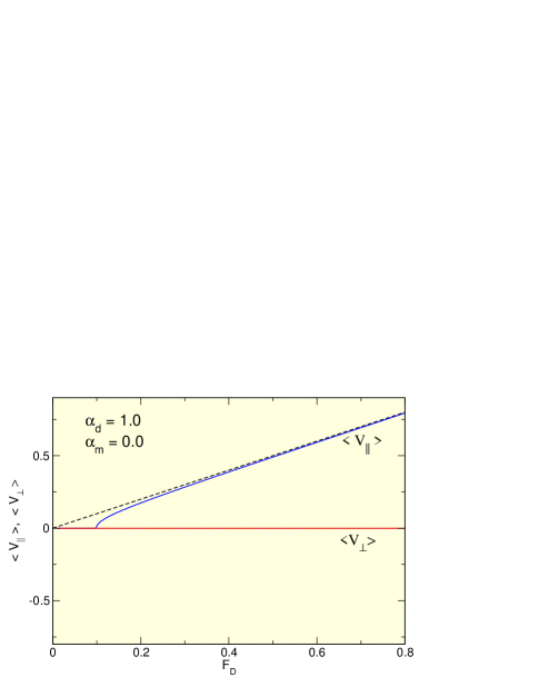
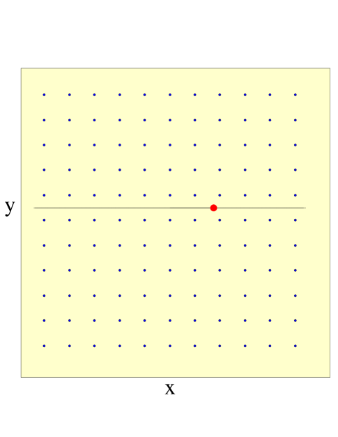
In Fig. 1 we plot and versus for a skyrmion moving over a periodic substrate in the overdamped case where and . Figure 2 shows the system geometry, highlighting the motion of the mobile skyrmion through the background of potential maxima. In Fig. 1 there is a depinning transition to a sliding state for as indicated by . Here the skyrmion moves strictly in the direction of the applied drive so that for all and . The dashed line in Fig. 1 is the expected value of in the clean limit, and we find that as increases, gradually approaches the clean limit value. Figure 2 shows the skyrmion trajectory for fixed , where motion occurs in a straight line along the driving direction.

III.1 Directional Locking
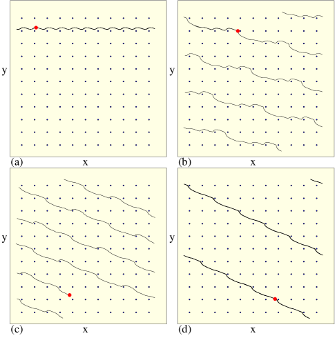
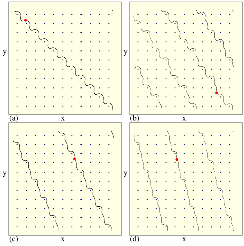
In Fig. 3 we illustrate the transport behavior in a sample with , , and . In the absence of a substrate the skyrmion would move at an angle of with respect to the drive direction and would have . Figure 3(a) shows and vs , and in Fig. 3(b) we plot vs . Here there is a transition from a pinned to sliding state just above . The skyrmion moves strictly in the direction of the drive for , which corresponds to the regime shown in Fig. 3(b) for the same interval of . Figure 4(a) shows the skyrmion trajectory in the region for for the system in Fig. 3(a). The skyrmion no longer passes through the centers of the potential minima but its trajectory shifts closer to the bottom row of potential maxima and develops an oscillation in the direction that was absent in the case shown in Fig. 2. As is further increased the skyrmion shifts even closer to the row of potential maxima and its velocity parallel to the drive decreases, as indicated by the dip in near . As increases further, both and increase, indicating that the skyrmion is now translating in the direction as well as in the direction. Additional dips in both and occur at higher , with occasional regions containing multiple closely spaced smaller dips. Figure 3 indicates that these dips correlate with the jumps in , and that between the dips, remains constant. This means that the direction of motion or Hall angle of the skyrmion changes in a discrete fashion with increasing . The steps in appear at values that are rational ratios of of the form , where and are integers. In Fig. 3(b) we highlight the steps at , 1/3, 2/5, 3/7, and . There are also numerous additional steps in for smaller intervals of for higher order rational ratios of . In general, the larger the values of and , the smaller the interval in over which the step appears.
During each step interval in , the skyrmion follows an ordered periodic orbit, translating substrate plaquettes in the direction perpendicular to the drive for every plaquettes it translates in the direction parallel to the drive. Figure 4(a) shows the orbit of a skyrmion in the state, while Fig. 4(b) illustrates the orbit in the state at . Here the skyrmion moves periodically through the system at an angle with respect to the drive direction. In each period of the motion, the skyrmion translates to the right by four plaquettes in the drive or direction and down by one plaquette in the perpendicular or direction, giving . At the transition out of the state, the skyrmion slows down, producing a cusp in the velocity curves in Fig. 3(b) and a dip in the net velocity near . A similar ordered orbit occurs in the state, where the skyrmion moves three plaquettes in the -direction and one plaquette in the direction during every period. There is another dip in the net skyrmion velocity near that occurs when the system transitions to the state. Figure 4(c) illustrates the orbit at this value of for . Here the periodic orbit is more extended and the skyrmion moves two plaquettes in the negative -direction for every five plaquettes in the -direction. Above the state, the system enters the state, followed by some higher order steps which occur over small intervals of as shown in Fig. 3(a) near . The system then reaches the state illustrated in Fig. 4(d) at , where the skyrmion moves two plaquettes in the -direction for every one plaquette in the -direction. At the other higher-order locking steps, similar ordered orbits appear.
The dips in and in Fig. 3 are associated with transitions in the skyrmion orbit from one directionally locked state to another, with a corresponding change in the Hall angle. The symmetry of the square lattice determines the specific directions along which the skyrmion motion locks, so that for other geometries such as a triangular substrate, the locking directions will be different. At the transitions between locking steps, the net skyrmion velocity decreases with increasing external drive . This phenomenon is known as negative differential mobility, and it has been observed in other systems where particles are driven over a periodic substrate, such as superconducting vortices moving over periodic pinning arrays where there are transitions between different dynamical phases 45 . Negative differential mobility is also a common feature in semiconductor devices 63 and can be useful for creating logic devices. The ability to control differential mobility in skyrmion systems could open new approaches for applications.
III.2 Overshoot Effect at
At in Fig. 3(b), , indicating the skyrmion is moving at a Hall angle of , which is higher than the clean limit value of or . This phenomenon occurs when the clean value of is oriented close to but slightly below a strong symmetry locking direction of the substrate. The skyrmion locks to the substrate and its Hall angle slightly exceeds that expected for the clean limit. As is increased, the effectiveness of the substrate is reduced and the direction of motion of the skyrmion gradually approaches the clean limit value, as shown in Fig. 5 where we plot a portion of the vs curve for the same system from Fig. 3(b) but for drives up to a higher value of . The dashed line in Fig. 5 indicates the clean value limit of . For , there is a jump from the state to a lower value of , followed by another jump to the state. There is then a small region where the system locks to the state before jumping to . As increases further, gradually approaches the clean limit value, as indicated by the dashed line in Fig. 5(b). This shows that there can be an overshoot effect in the locking behavior for a certain range of drives, giving rise to non-monotonic behavior of as a function of . We have observed similar overshoot effects for other values of .
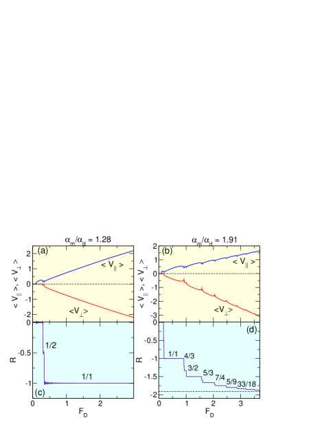
III.3 Higher Order Steps
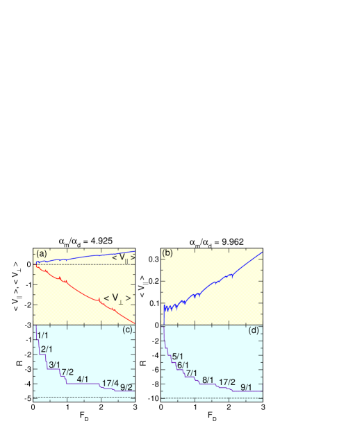
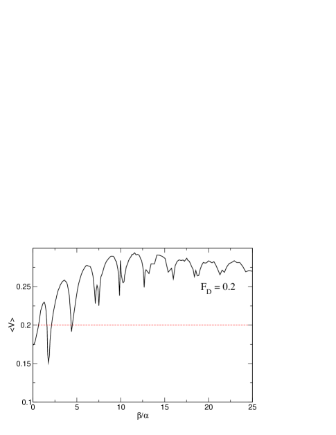
The specific features in the velocity force curves are strongly dependent on the value of . In Fig. 6(a,b) we show and for and , respectively, while in Fig. 6(c,d) we plot the corresponding vs curves. For , the system is predominantly locked to the step as shown in Fig. 6(b). On this step, the skyrmion moves along the direction as illustrated in Fig. 7(a) for . Here the skyrmion follows a sinusoidal trajectory, moving by one plaquette in the -direction and one plaquette in the -direction in a single period. At values of higher than those plotted in Fig. 6(a), further locking steps occur as approaches . At , a larger number of steps occur, as indicated in Fig. 6(d) where we highlight the , 4/3, 3/2, 5/3, 7/4, 5/9, and steps. For values higher than those shown in Fig. 6(d), additional steps appear as approaches the clean limit value. Figure 7(b) illustrates the skyrmion trajectory on the step for the system in Fig. 6(b). The skyrmion moves five plaquettes in the direction perpendicular to the drive for every three plaquettes in the direction parallel to the drive during a single period. Fig. 8(a) shows and versus for a sample with , and the corresponding vs curve appears in Fig. 8(c). In this case, the clean limit Hall angle is large, and there is no longer a phase where the skyrmions move only in the direction of the drive, so the step is lost. Instead, above depinning the motion jumps straight into the state. This is followed by steps at , 3/1, 7/2, 4/1, 17/4, and . There are also numerous smaller intermediate steps corresponding to higher order fractions. In Fig. 7(c) we plot the skyrmion orbit on the step for the system in Fig. 8(a,c), while Fig. 7(d) shows the skyrmion orbit at for the same system. In general, as increases, more steps become visible. In Fig. 8(b) we plot only versus for a sample with to show more clearly the increased number of features in the velocity-force curve. Figure 8(d) shows the corresponding vs curve, where we highlight the steps at , 6/1, 7/1, 8/1, 17/2, and . The largest observable integer step has a value of that is the largest integer which is smaller or equal to the value of .
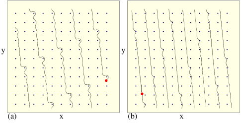
In Fig. 9(a) we plot the skyrmion trajectories at for the system in Fig. 8(b,d) with , showing that the skyrmions circle around every fifth substrate maximum. At , shown in Fig. 9(b), the trajectories are much straighter and the skyrmion moves at an angle that causes it to translate by eight plaquettes in the negative direction for every one plaquette in the positive -direction.

III.4 Arnol’d Tongues
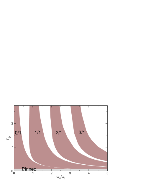
By conducting a series of simulations for varied we can examine the evolution of the different locking phases. In Fig. 10 we show the evolution of the pinned phase and the , 1/1, 2/1, and locking phases for and . The depinning threshold for the pinned phase remains roughly constant as a function of . For small , the skyrmion motion is strictly in the direction as indicated by the presence of the phase. As increases, the range and the width of the lower order locking phases decreases while new locking phases appear. The regions in which the locking occurs have the characteristic features of Arnol’d tongues, which occur in dynamical systems when there are two competing frequencies 59 ; 60 . In our system, the two frequencies are given by the inverse rate of translation along the x direction and the inverse rate of translation along the y direction when the system is on a locking step. These frequencies are quantized on the step due to the periodicity of the substrate; unlike the case of Shapiro steps, we do not apply any ac drive and the frequencies arise from the combination of dc motion and the substrate. If the substrate were rectangular instead of square, a different set of Arnol’d tongues would arise. At higher values of , a larger number of locking steps appear in the velocity-force curves. For example, at , as increases the system passes through a small region of followed by the locking phase and then by the phase. Another feature of the phase diagram is that at higher drives the width of each locking phase decreases. To illustrate this more clearly, we focus on the width of the step as a function of , as highlighted in Fig. 11(a) where we plot the location of the step over the narrow range out to , much higher than the maximum value of shown in Fig. 10. The lower edge of the locking regime, which was dropping to lower values of with increasing in Fig. 10, bends back around for higher as shown in Fig. 11, and shifts to higher with increasing . The resulting nose structure is the origin of the overshoot phenomenon, where over a certain range of , the system locks to the step for lower only to drop out of that step as increases. Here the skyrmions can lock to the direction even though their resulting motion follows a higher angle than would occur in a clean system. As increases above the edge of the step, the skyrmion jumps to smaller values of in a series of steps. On each step the skyrmion locks to different symmetry directions which are closer to the clean system value of . The overall shape of the step is shown in Fig. 11(b), where we plot the range and . There is a decrease in the extent of the locking phase at higher drives and at higher values. The width of the step gradually decreases and approaches a point centered at the value for the highest drives. We find that the regions over which the other integer locking phases occur have similar shapes to that shown in Fig. 11(b).
III.5 Overshoot Effect for Varied
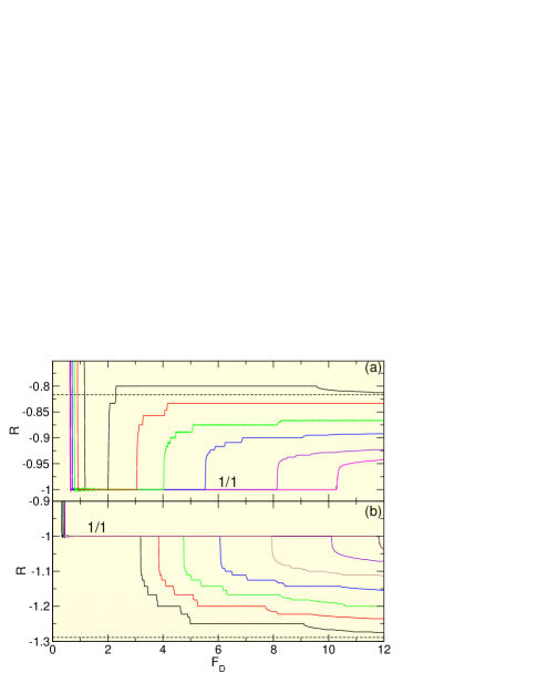
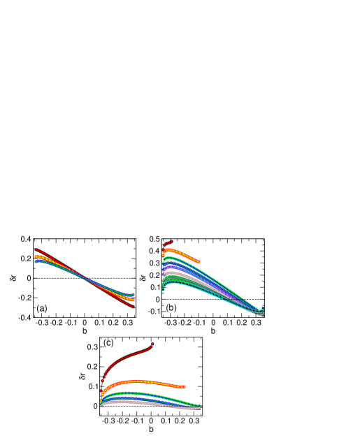
A new set of locking steps arises for values of greater than that where the locking occurs in Fig. 11(a). In Fig. 12(a) we plot versus for different values of on the side of the locking phase shown in Fig. 11(b), where an overshoot effect occurs. The dashed line is the value of at in the clean limit; similar overshoots occur for the other values of . The black curve shows that for in the presence of a substrate, the skyrmion locks to the direction for and then jumps to the state. For , jumps off of the step and, for higher values of , further small jumps in occur as approaches the clean value limit. As is increased toward , the width of the interval of over which the system is locked to the step increases since the clean limit Hall angle is closer to the angle of . In each case, when the system jumps out of the step for increasing , it can jump into a series of other locking steps as gradually approaches the clean value. In Fig. 12(b) we plot versus for the side of the locking phase from Fig. 11(b). The dashed line indicates the clean limit value of for . As approaches from above, the extent of the region over which the system is locked to the state again increases. After jumping out of the state, the system jumps to larger values of in a series of smaller locking steps as it approaches the clean limit value of . We observe similar changes in for the other integer locking phases such as and .
III.6 Fractional Locking
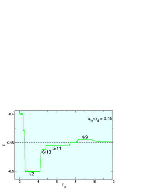
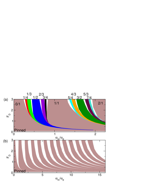
In Fig. 13(a) we plot the locking phases as a function of and over the range , highlighting the fractional locking steps at the , 1/3, 1/2, 2/3, 3/4, 5/4, 4/3, 3/2, 5/3, and states falling between the integer steps at , 1/1, and 2/1. Here the widths of the fractional locking states behave similarly to those of the integer locking states. Figure 13(a) shows that for certain values of , the fractional steps will be the dominant feature observed in transport. The higher order fractional steps, not shown in the figure, exhibit similar features. The overshoot effect described for the locking step in Fig. 11 occurs for all of the integer and fractional locking steps as well, with the overall width of each of the steps decreasing with increasing . In Fig. 13(b) we plot only the integer locking regions from to as a function of and for the range . Between each of the integer steps, there is a series of fractional steps (not shown) similar to that illustrated in Fig. 13(a). The fractional steps have the form , where are the integer steps.
III.7 Speedup Effects
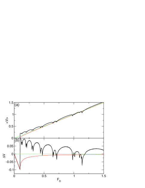
The Magnus term can produce an acceleration or speedup effect of the skyrmion, in which the speed of the skyrmion is higher in the presence of a substrate than it would be in the absence of a substrate or in the overdamped limit. In Fig. 14(a) we plot the net skyrmion velocity versus for , the overdamped case of , and the clean limit. In the overdamped case, is always smaller than the clean limit value, indicating that the substrate does not accelerate the skyrmion. In contrast, for there are clear regions where is higher than the clean value. This effect is most prominent for values of just above the depinning threshold. To show the speedup more clearly, in Fig. 14(b) we plot for and 0.0. For the overdamped case, over the entire range of . The lowest values of occur just at depinning, and then gradually approaches zero as increases. The behavior of the overdamped system is similar to the velocity-force curves observed in other overdamped systems such as colloids driven over periodic substrate arrays47 ; 48 . For , shows a series of peaks which are correlated with transitions between the different locking regimes. For , due to the speedup effect, where there is an enhancement in the net velocity of up to twice the velocity in the clean limit. As is further increased the magnitude of the speedup effect decreases and there are several intervals of where the skyrmion is moving significantly slower than it would in the clean limit. For further increases in , approaches zero. The speedup effect is generated by the non-dissipative terms in the equation of motion which cause the skyrmions to be accelerated through certain portions of the substrate potential.
In Fig. 15 we plot versus for a fixed , where the dashed line indicates the clean limit value of . Values of indicate a speedup effect. For , in the overdamped limit, . We find a series of oscillations in corresponding to the different locking phases through which the system passes as a function of . Here, the magnitude of the speedup effect increases on average with increasing .
A speedup effect for a driven skyrmion interacting with a defect has also been observed in simulations by Müller and Rosch, who find that for some cases the defect causes a net increase in the skyrmion velocity 27 . They also find that the magnitude of the speedup effect decreases when an externally imposed skyrmion drift velocity is increased. This is similar to what we observe for the periodic substrate case where for increasing external driving force the speedup effect is reduced as shown in Fig. 14(b). In Ref. 27 the speedup was up to an order of magnitude higher than the velocity in the clean limit, while we observe a velocity enhancement of only up to a factor of 2. This is because in our system there is a minimum critical force required to depin the skyrmion, whereas in Ref. 27 there was no lower bound on the imposed drift velocity. Since the speedup is increased for lower drives, Müller and Rosch could access lower drives and obtain larger velocity enhancements from the speedup effect.
III.8 Two Dimensional Analytic Substrate
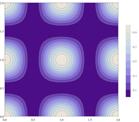

In order to understand how general our results are for different details of the periodic substrate, we next consider a 2D analytic substrate with the same lattice constant used in obtaining the previous results. The force from the substrate is given by , where is the maximum force exerted by the substrate and is the lattice constant as in the system shown in Fig. 2. Figure 16 shows a gray scale of a portion of the substrate, where the potential maxima are highlighted. In Fig. 17(a) we plot versus for a skyrmion moving over a substrate with for . The dashed line indicates the clean limit value of . Figure 17(b) shows and vs for the same system, while in Fig. 17(c) we plot the corresponding vs curve with a dashed line indicating the value of in a clean system and with the locking steps at , 2/1, 3/1, and highlighted. Although there are some differences in the details, we find the same general transport features for the analytic substrate as we observed for the pinned skyrmion substrate at , including the locking of the skyrmion motion to different symmetry directions and the steps in at integer and fractional ratios of . Figure 17(a) shows that there are a similar series of dips in corresponding to transitions between the different locking phases. We find that with an analytic potential, a somewhat larger number of small looking steps can be resolved, as shown for in Fig. 17(a), and the steps in in Fig. 17(c) for this region have a devil’s staircase structure. Figure 17(a) also shows that exhibits regions where it is higher than the clean limit (dashed line), indicating that the same type of speedup effect occurs for the analytic potential. We have also examined the locking effects on the analytic potential for other values of and , and find that all the features highlighted in Fig. 17 are robust. This indicates that the directional locking effect is a generic feature of skyrmions moving over periodic substrates.
IV Scattering Off a Single Pinning Site
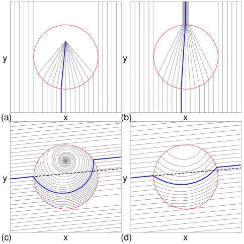
In order to better understand the dependence of the Hall angle on the external drive, we consider the case of a skyrmion scattering from a single pinning site. We drive the skyrmion toward the pinning site for varied impact parameters , and measure the resulting shift in the skyrmion position perpendicular to the driving force for the outgoing state. We model the pinning site as a parabolic trap with radius and a maximum force of . The skyrmion is driven from a point outside the trap towards the trap with an external drive applied in the positive -direction. In Fig. 18(a) we show the overdamped case with , , , and , We highlight the trajectory of a skyrmion with an impact parameter of . For this value of , all skyrmion trajectories that contact the pinning site form straight lines directed toward the equilibrium position of the pinned state along the line. The pinned equilibrium position is shifted in the positive -direction from the center of the pinning site due to the applied external force. Figure 18(b) shows the same system with higher . The trajectories are shifted toward the center of the pinning site, but since the skyrmions can escape from the pinning site. The trajectory for an impact parameter comes in and out of the pinning site at , so there is no shift, while the shift of the trajectories for non-zero impact parameters are symmetric across .
Fig. 18(c) shows the trajectories for the same system at for , where the external drive is still applied in the positive -direction. In this case, the trajectories that do not intersect with the pinning site move at an angle of with respect to the -axis. The dashed line represents the trajectory a skyrmion would follow in the absence of the pinning site. When the skyrmion moves through the pinning site, the trajectory is no longer straight as in the overdamped case but is now strongly curved due to the Magnus force. The skyrmions that encounter the pinning site on the upper left side become trapped by entering a spiral trajectory that carries them to the equilibrium pinned position in the upper portion of the pinning site. Skyrmions that enter the pinning site on the lower left side can escape from the pin; however, the position of the outgoing skyrmions are shifted in the positive direction as indicated by the highlighted trajectory in Fig. 18(c). This shift is similar to the side jump effect that occurs for electron scattering 64 , where the interaction with pinning or disorder shifts the outgoing trajectory of the particle relative to its incoming trajectory. In the case of a periodic substrate, a skyrmion would be repeatedly shifted as it moves through the system, so that for the average direction of skyrmion motion follows a Hall angle that is less than the clean value limit of . Figure 18(c) also shows that when the skyrmion is captured it becomes pinned along the line at a position above the center of the pin. The shift of the pinned equilibrium position to this location is caused by the bias from the external drive, and the location of the equilibrium position is not changed by the inclusion of a finite Magnus term. Figure 18(d) shows the trajectory for with a higher drive of . Here, the size of the side jump is reduced, so that the Hall angle that would be observed for motion through a periodic substrate is closer to the pin-free value of . This indicates that the Hall angle increases with increasing driving force, as also observed in the simulations with a periodic substrate. The shift is reduced at the higher drives in Fig. 18(d), since the skyrmion is moving more rapidly through the pinning site and the trajectory spends less time being bent.
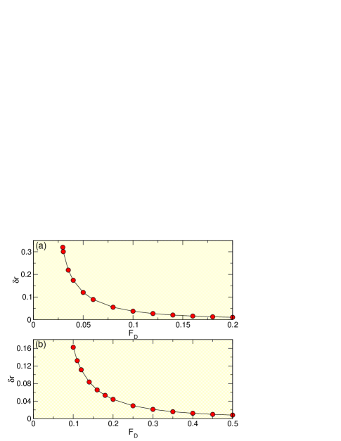
To quantify the the dependence of the magnitude of the shift or side jump of the trajectory as a function of the external drive, in Fig. 19 we plot for a skyrmion approaching the pinning site with . Figure 19(a) shows the shift for , , and . The shift is highest at low , starting near in Fig. 19(a) and gradually approaching zero as increases. In Fig. 19(b) we plot versus for a sample with , , and . Here the initial value of is smaller due to the smaller value of . From an initial value of , the magnitude of the shift decreases with increasing drive. For (not shown), for all values of . If we apply a fit to the decrease of the shift as a function of drive, we find , with depending on the choice of the low drive cutoff. In the work of Müller and Rosch for a skyrmion scattering off a single defect 27 , they found through both simulations and perturbation that the shift as a function of drive goes as . Even though the pinning potential we use has a different form than that used in Ref. 27 , our results are consistent with the pinning site inducing a trajectory shift.
In order to understand the shift of the skyrmion and when the skyrmion will be captured by a pinning site, in Fig. 20 we plot as a function of the impact parameter . Figure 20(a) shows the overdamped case for and at , 0.16, and . At , and there is no shift in the trajectory, while shifts for positive and negative values of are symmetric across so that the integrated shift over all impact parameters is zero. For the skyrmion is always captured by the pin. Figure 20(b) shows versus for a sample with at drives ranging from to . Here, decreases with increasing , and the shifts are asymmetric for positive and negative values of , so that the integrated shift over all impact parameters is positive. At and , values of at which there are no points on the curve indicate that the skyrmion was captured by the pinning site. For higher values of , is larger for than for . The results in Fig. 20(b) show that increasing reduces the range of impact parameters where an incoming skyrmion is captured by the pin, and that for some ranges of a skyrmion can escape the pin even when , in contrast to the overdamped case where the skyrmion is always trapped whenever .
Figure 20(c) shows versus for over the range to . Here, the ability of the pinning site to capture the skyrmion is further reduced, and the skyrmion does not become pinned for more than half the impact parameters at even though this drive is substantially smaller than the maximum pinning force . At a skyrmion can only become captured if . The overall shifts are positive over a much wider range of , and the magnitude of decreases with increasing . This result shows that inclusion of a Magnus term in the dynamics reduces the ability of pinning sites to capture particles since the Magnus term induces a side jump or shift that permits the particles to escape from the pin.
V Conclusion
We have numerically examined a skyrmion under a dc drive moving over a two-dimensional square pinning substrate for varied ratios of the Magnus force term to the damping . In the overdamped limit , there is a single depinning transition into a sliding state where the skyrmion moves in the direction of the applied drive. For a finite we find that the skyrmion direction of motion or Hall angle depends on the magnitude of the external drive and gradually approaches the substrate-free limit at high drives. Due to the symmetry of the underlying substrate, the Hall angle does not change continuously but passes through a series of steps as the skyrmion motion becomes locked to certain symmetry directions of the substrate. These steps occur at integer and rational fractional ratios of the perpendicular to parallel velocity components of the skyrmion motion with respect to the direction of the applied drive, where and are the number of plaquettes the skyrmion moves in the perpendicular and parallel directions, respectively. We find that the Hall angle generally increases with increasing external drive, but that there can be an overshoot effect in which the Hall angle is larger than expected for the substrate-free or clean limit. In this case, as the drive increases the Hall angle jumps back to a lower value closer to the clean limit value. At the transitions between different directional looking steps, the skyrmion velocity shows a striking series of cusps or dips where the skyrmion slows down for increasing , producing a negative differential mobility at the transitions. As increases, the number of transitions between different looking steps increases, as we map out in a series of phase diagrams. The directional locking effects exhibited by the skyrmions are very distinct from the directional locking effects previously observed for overdamped particles such as vortices and colloids interacting with periodic substrates. In the overdamped system, the angle of the external drive must be changed with respect to the symmetry direction of the substrate in order to induce locking steps, whereas for the skyrmion system the driving direction remains fixed; only the magnitude of the driving force is changed. Additionally, the overdamped systems exhibit neither the negative mobility phenomenon at the transitions between steps nor the overshoot effect.
We find that the skyrmion motion can exhibit a speedup or acceleration effect where the interaction of the skyrmion with a pinning site can accelerate the skyrmion such that the skyrmion velocity is higher than the value that would be induced by the external drive alone. This effect is generally enhanced at the lower drives and suppressed near the directional locking transitions. It contrasts strongly with the behavior of overdamped systems, where interactions with pinning or a substrate always decrease the velocity of an overdamped particle. We find that all of these features are robust for different forms of the periodic substrate.
To better understand how the pinning can induce a Hall angle dependence on the magnitude of the drive, we consider a skyrmion scattering from a single pinning site. In the overdamped limit with , the skyrmion becomes trapped by the pin whenever the external drive is less than the magnitude of the maximum pinning force that can be exerted by the pinning site. For external drives larger than this value, the skyrmion escapes from the pin and its trajectory is shifted perpendicular to the direction of skyrmion motion. The shift is symmetric for positive and negative impact parameters, so there is no net shift of the trajectory when all impact parameters are integrated. In contrast, at a finite , the magnitude of the trajectory shift depends asymmetrically on the impact parameter, producing a nonzero net shift of the skyrmion as it moves through the pinning site when all impact parameters are integrated. This shift is similar to the side jump phenomenon found in electron scattering. As the external drive is increased, the net shift decreases and the skyrmion motion approaches the pin-free trajectory track. The trajectory shift is responsible for the modified Hall angle experienced by the skyrmion at low drives, and the gradual decrease in shift with increasing drive causes the Hall angle to gradually approach the clean limit value. For the case of a periodic substrate, the additional symmetry of the substrate prevents the angle of the skyrmion motion from changing continuously; instead, the motion changes in a series of steps with increasing drive as it approaches the clean limit value. We also find that for finite , depending on the impact parameter the skyrmion may or may not become pinned regardless of whether the maximum pinning force is smaller than the driving force, and that for increasing , the range of impact parameters over which the particle is not pinned even when the driving force is smaller than the maximum pinning force increases. This is one of the reasons that pinning of skyrmions is much weaker than pinning in overdamped systems such as superconducting vortices.
Acknowledgements.
This work was carried out under the auspices of the NNSA of the U.S. DoE at LANL under Contract No. DE-AC52-06NA25396.References
- (1) A. Bogdanov and A. Hubert, J. Magn. Magn. Mater. 138, 255 (1994); U. K. Rößler, A. N. Bogdanov, and C. Pfleiderer, Nature (London) 442, 797 (2006).
- (2) S. Mühlbauer, B. Binz, F. Jonietz, C. Pfleiderer, A. Rosch, A. Neubauer, R. Georgii, and P. Böni, Science 323, 915 (2009).
- (3) X.Z. Yu, Y. Onose, N. Kanazawa, J.H. Park, J.H. Han, Y. Matsui, M. Nagaosa, and Y. Tokura, Nature 465, 901 (2010).
- (4) X.Z. Yu, N. Kanazawa, Y. Onose, K. Kimoto, W.Z. Zhang, S. Ishiwata, Y. Matsui, and Y. Tokura, Nature Mater. 10, 106 (2011).
- (5) S. Seki, X.Z. Yu, S. Ishiwata, and Y. Tokura, Science 336, 198 (2012).
- (6) S.X. Huang and C.L. Chien, Phys. Rev. Lett. 108, 267201 (2012).
- (7) X.Z. Yu, N. Kanazawa, W.Z. Zhang, T. Nagai, T. Hara, K. Kimoto, Y. Matsui, Y. Onose, and Y. Tokura, Nature Commun. 3, 988 (2012).
- (8) S. Heinze, K. von Bergmann, M. Menzel, J. Brede, A. Kubetzka, R. Wiesendanger, G. Bihlmayer, and S. Blügel, Nature Phys. 7, 713 (2011).
- (9) N. Nagaosa and Y. Tokura, Nature Nanotech. 8, 899 (2013).
- (10) X.Z. Yu, Y. Tokunaga, Y. Kaneko, W.Z. Zhang, K. Kimoto, Y. Matsui, Y. Taguchi, and Y. Tokura, Nature Commun. 5, 3198 (2014).
- (11) A.B. Butenko, A.A. Leonov, U.K. Rößler, and A.N. Bogdanov, Phys. Rev. B 82, 052403 (2010).
- (12) R.L. Silva, L.D. Secchin, W.A. Moura-Melo, A.R. Pereira, and R.L. Stamps, Phys. Rev. B 89, 054434 (2014).
- (13) S. Polesya, S. Mankovsky, S. Bornemann, D. Ködderitzsch, J. Minár, and H. Ebert, Phys. Rev. B 89, 184414 (2014).
- (14) S. Banerjee, J. Rowland, O. Erten, and M. Randeria, Phys. Rev. X 4, 031045 (2014).
- (15) N. Ronning, C. Hanneken, M. Menzel, J.E. Bickel, B. Wolter, K. von Bergmann, A. Kubetzka, and R. Wiesendanger, Science 341, 636 (2013).
- (16) P. Milde, D. Köhler, J. Seidel, L.M. Eng, A. Bauer, A. Chacon, J. Kindervater, S. Mühlbauer, C. Pfleiderer, S. Buhrandt, C. Schütte, and A. Rosch, Science 340, 1076 (2013).
- (17) G. Blatter, M.V. Feigelman, V.B. Geshkenbein, A.I. Larkin, and V.M. Vinokur, Rev. Mod. Phys. 66, 1125 (1994).
- (18) F. Jonietz, S. Mühlbauer, C. Pfleiderer, A. Neubauer, W. Münzer, A. Bauer, T. Adams, R. Georgii, P. Böni, R.A. Duine, K. Everschor, M. Garst, and A. Rosch, Science 330, 1648 (2010).
- (19) J. Zang, M. Mostovoy, J.H. Han, and N. Nagaosa, Phys. Rev. Lett. 107, 136804 (2011).
- (20) T. Schulz, R. Ritz, A. Bauer, M. Halder, M. Wagner, C. Franz, C. Pfleiderer, K. Everschor, M. Garst, and A. Rosch, Nature Phys. 8, 301 (2012).
- (21) J. Iwasaki, M. Mochizuki, and N. Nagaosa, Nature Commun. 4, 1463 (2013).
- (22) S.-Z. Lin, C. Reichhardt, C.D. Batista, and A. Saxena, Phys. Rev. B 87, 214419 (2013).
- (23) S.-Z. Lin, C. Reichhardt, C.D. Batista, and A. Saxena, J. Appl. Phys. 115, 17D109 (2014).
- (24) R.E. Troncoso and A.S. Núñez, Phys. Rev. B 89, 224403 (2014).
- (25) C. Reichhardt, D. Ray, and C.J. Olson Reichhardt, arXiv:1409.5457.
- (26) J. Müller and A. Rosch, arXiv:1411.2857.
- (27) K. Everschor, M. Garst, B. Binz, F. Jonietz, S. Mühlbauer, C. Pfleiderer, and A. Rosch, Phys. Rev. B 86, 054432 (2012).
- (28) L. Kong and J. Zang, Phys. Rev. Lett. 111, 067203 (2013).
- (29) M. Mochizuki, X.Z. Yu, S. Seki, N. Kanazawa, W. Koshibae, J. Zang, M. Mostovoy, Y. Tokura, and N. Nagaosa, Nature Mater. 13, 241 (2014).
- (30) A.A. Kovalev, Phys. Rev. B 89, 241101(R) (2014).
- (31) S.-Z. Lin, C.D. Batista, C. Reichhardt, and A. Saxena, Phys. Rev. Lett. 112, 187203 (2014).
- (32) Y.-H. Liu, Y.-Q. Li, and J.H. Han, Phys. Rev. B 87, 100402 (2013).
- (33) J.S. White, K. Prša, P. Huang, A. A. Omrani, I. Živković, M. Bartkowiak, H. Berger, A. Magrez, J.L. Gavilano, G. Nagy, J. Zang, and H.M. Rønnow, Phys. Rev. Lett. 113, 107203 (2014).
- (34) A. Fert, V. Cros, and J. Sampaio, Nature Nanotech. 8, 152 (2013).
- (35) J. Sampaio, V. Cros, S. Rohart, A. Thiaville, and A. Fert, Nature Nanotech. 8, 839 (2013).
- (36) Y. Zhou and M. Ezawa, Nature Commun. 5, 4652 (2014).
- (37) S. Bhattacharya and M.J. Higgins, Phys. Rev. Lett. 70, 2617 (1993).
- (38) A.E. Koshelev and V.M. Vinokur, Phys. Rev. Lett. 73, 3580 (1994); C.J. Olson, C. Reichhardt, and F. Nori, Phys. Rev. Lett. 81, 3757 (1998).
- (39) H. Fangohr, S.J. Cox, and P.A.J. de Groot, Phys. Rev. B 64, 064505 (2001).
- (40) A.A. Thiele, Phys. Rev. Lett. 30, 230 (1973).
- (41) K. Harada, O. Kamimura, H. Kasai, T. Matsuda, A. Tonomura, and V.V. Moshchalkov, Science 274, 1167 (1996).
- (42) C. Reichhardt, C. J. Olson, and F. Nori, Phys. Rev. B 57, 7937 (1998).
- (43) J. Gutierrez, A.V. Silhanek, J. Van de Vondel, W. Gillijns, and V.V. Moshchalkov, Phys. Rev. B 80, 140514 (2009); S. Avci, Z.L. Xiao, J. Hua, A. Imre, R. Divan, J. Pearson, U. Welp, W.K. Kwok, and G.W. Crabtree, Appl. Phys. Lett. 97, 042511 (2010).
- (44) T. Bohlein, J. Mikhael, and C. Bechinger, Nature Mater. 11, 126 (2012).
- (45) C. Reichhardt and F. Nori, Phys. Rev. Lett. 82, 414 (1999).
- (46) P.T. Korda, M.B. Taylor, and D.G. Grier, Phys. Rev. Lett. 89, 128301 (2002).
- (47) M.P. MacDonald, G.C. Spalding, and K. Dholakia, Nature (London) 426, 421 (2003).
- (48) A. Gopinathan and D.G. Grier, Phys. Rev. Lett. 92, 130602 (2004).
- (49) C. Reichhardt and C. Olson Reichhardt, Phys. Rev. E 69, 041405 (2004).
- (50) A.M. Lacasta, J.M. Sancho, A.H. Romero, and K. Lindenberg, Phys. Rev. Lett. 94, 160601 (2005).
- (51) M. Balvin, E. Sohn, T. Iracki, G. Drazer, and J. Frechette, Phys. Rev. Lett. 103, 078301 (2009). S.R. Risbud and G. Drazer, Phys. Rev. E 90, 012302 (2014).
- (52) C. Reichhardt and C. J. Olson Reichhardt, Phys. Rev. Lett. 106, 060603 (2011); T. Bohlein and C. Bechinger, Phys. Rev. Lett. 109, 058301 (2012).
- (53) H.G. Schuster, Deterministic Chaos (VCH Verlag, Weinheim, 1988).
- (54) P. Bak, Phys. Today 39(12), 38 (1986).
- (55) S. Shapiro, Phys. Rev. Lett 11, 80, (1963); A. Barone and G. Paterno, Physics and Applications of the Josephson Effect (John Wiley, New York, 1982).
- (56) C. Reichhardt, R.T. Scalettar, G.T. Zimányi, and N. Grønbech-Jensen, Phys. Rev. B 61, R11914(R) (2000).
- (57) E. Scholl, Nonequilibrium Phase Transitions in Semiconductors (Springer-Verlag, Berlin, 1987).
- (58) A. Vanossi, N. Manini, and E. Tosatti, Proc. Natl. Acad. Sci. (USA) 109, 16429 (2012); D. McDermott, J. Amelang, C.J. Olson Reichhardt, and C. Reichhardt, Phys. Rev. E 88, 062301 (2013).
- (59) L. Berger, Phys. Rev. B 2 4559, (1970).