Intraband and interband spin-orbit torques in non-centrosymmetric ferromagnets
Abstract
Intraband and interband contributions to the current-driven spin-orbit torque in magnetic materials lacking inversion symmetry are theoretically studied using Kubo formula. In addition to the current-driven field-like torque ( being a unit vector determined by the symmetry of the spin-orbit coupling), we explore the intrinsic contribution arising from impurity-independent interband transitions and producing an anti-damping-like torque of the form . Analytical expressions are obtained in the model case of a magnetic Rashba two-dimensional electron gas, while numerical calculations have been performed on a dilute magnetic semiconductor (Ga,Mn)As modeled by the Kohn-Luttinger Hamiltonian exchanged coupled to the Mn moments. Parametric dependences of the different torque components and similarities to the analytical results of the Rashba two-dimensional electron gas in the weak disorder limit are described.
pacs:
72.25.Dc,72.20.My,75.50.PpI Introduction
Magnetization dynamics driven electrically by spin-polarized currents through the spin transfer torqueslonczewski-jmmm-1996 ; berger-prb-1996 ; ralph-jmmm-2008 has attracted considerable attention due to its applications in memory and logic spintronic devices.Chappert-nm-2007 ; Brataas-nm-2012 An alternative mechanism, the spin-orbit torque (SOT), has been recently proposed as a means to control the magnetization of a single ferromagneticbernevig ; manchon-prb ; Obata-prb-2008 or even antiferromagneticZelezny:2014_a layer without the need of an external spin-polarizer. The SOT arises from the interaction between the nonequilibrium spin density of carriers and the local magnetization. The non-equilibrium spin density results from the transfer of angular momentum between the spin and orbital degrees of freedom of the carriers.bernevig ; manchon-prb ; Obata-prb-2008 ; garate-prb-2009 ; pesin2012 ; bijl2012 ; kim2012 ; wang-manchon-2012 ; Hang-apl-2013 The SOT requires magnetic structures with strong spin-orbit coupling and inversion symmetry breaking. Initially observed in epilayers of (Ga,Mn)As dilute magnetic semiconductors (DMSs) with bulk inversion asymmetry in their strained zinc-blende crystal,chernyshov-nph-2009 ; endo-apl-2010 ; fang-nanotech-2011 this effect was soon widely confirmed in metallic bilayers with structural inversion symmetry breaking.miron1 ; miron2 ; liu ; kim ; garello ; fan ; jamali ; mellnik In general, the SOT observed experimentally possesses two components, a field-like torque odd in the magnetization direction and an anti-damping-like torquenote2 even in m. Here, is a unit vector determined by the symmetry of the structure and the current direction,note1 and and are the magnitudes of the field-like and anti-damping-like torque, respectively. These torques are also commonly referred to as the out-of-plane and in-plane torques, respectively, with respect to the () plane. The direction of the field-like (out-of-plane) and anti-damping-like (in-plane) torques and their detailed angular dependencenote1 depend on the crystal structure, while their magnitude has been shown to strongly depend on the materials considered. kim ; garello ; fan ; jamali ; mellnik
Two main mechanisms have been invoked to explain the origin of the current-driven torques in non-centrosymmetric ferromagnets. In the first scenario, the lack of inversion symmetry enables the inverse spin galvanic effectisge-reviews (ISGE), i.e. flowing current directly produces a nonequilibrium spin density locally, whose direction is determined by the symmetry of the spin-orbit coupling. Recently, it has been proposed that in non-centrosymmetric magnetic materials this nonequilibrium spin density may exert a torque on the magnetizationbernevig ; manchon-prb ; Obata-prb-2008 ; garate-prb-2009 . Here, is the gyromagnetic ratio, the density of magnetic moments and the exchange coupling (having the dimension of energy) between the itinerant electron spins and the local magnetization which, in this article, is assumed to arise solely from localized magnetic moments so that the saturated magnetization . This is the essence of the ISGE-induced SOT. Alternatively, in ferromagnets adjacent to a heavy metal, it has also been proposed that the spin Hall effect (SHE) present in the heavy metal may inject a spin-polarized current into the adjacent ferromagnet, exerting a spin-transfer torque (STT) on the magnetization.liu ; haneyboltz ; miron2
A current debate aims at identifying the interplay between these different mechanisms and their impact in terms of current-driven spin torque. In the simplest physical picture, SHE induces an anti-damping-like STT, while the SOT reduces to a field-like torque generated by ISGE.haneyboltz However, it has been recently proposed that the incomplete absorption of the SHE-induced spin current by the ferromagnet (or, equivalently, the non-vanishing imaginary part of the interfacial spin mixing conductance) may result in a field-like STT component.haneyboltz Similarly, in the context of ISGE-induced SOT, recent theories have suggested that spin relaxation and dephasing may also lead to a correction in the SOT in the form of a anti-damping-like component.pesin2012 ; bijl2012 ; kim2012 ; wang-manchon-2012 In Refs. bijl2012, and kim2012, , the anti-damping-like SOT term arises from the electron scattering-induced spin relaxation. In Ref. haneyboltz, , the semiclassical diffusion formalism was used, whereas in Refs. pesin2012, and wang-manchon-2012, , the anti-damping-like SOT is obtained within a quantum kinetic formalism. It is ascribed to spin-dependent carrier lifetimes pesin2012 or to a term arising from the weak-diffusion limit, which in the leading order is proportional to a constant carrier lifetime.wang-manchon-2012
Intriguing material-dependence of the SOTs has been unravelled in various experiments keeping the debate on the origin of these components open.kim ; garello ; fan ; jamali ; mellnik The difficulty in determining the physical origin of the torques partly lies in the complexity of the ultrathin bilayer considered, involving both bulk and interfacial transport in the current-in-plane configuration. First principle calculations have indeed pointed out the significant sensitivity of the torques to the nature of the interfaces.haneydft
In a recent publication, Kurebayashi et al.Kurebayashi investigated the SOT in a bulk DMS. They observed a large anti-damping-like torque that is not ascribed to the SHE since no adjacent spin-orbit coupled paramagnet is present. It was then proposed that such a torque has a scattering-independent origin in the Berry curvature of the band structure, in a similar spirit as the intrinsic SHE was introduced about ten years ago.sinova2004 ; Murakami:2003_a
In this paper, we present a systematic theoretical study of SOTs arising from the ISGE and Berry curvature mechanisms in a spin-independent relaxation time approximation. We focus our attention on the current-driven spin-orbit field (called the SOT field), , producing the spin-orbit torque . These SOT fields have an in-plane component of the ISGE originnote1 [i.e. lying in the () plane and producing an out-of-plane torque] and also an intrinsic contribution arising from interband transitions. The latterKurebayashi produces an out-of-plane field of the form [i.e. lying perpendicular to the () plane]. Analytical expressions are obtained in the model case of a magnetic Rashba two-dimensional electron gas (2DEG), while numerical calculations are performed on DMSs described by the kinetic-exchange Kohn-Luttinger Hamiltonian.dms-rmp Parametric dependences of the different torque components and similarities to the analytical results of the Rashba two-dimensional electron gas in the weak disorder limit are described.
II Non-equilibrium spin density: intraband and Interband Contributions in Kubo formula
In the present study, we start from a general single-particle Hamiltonian
| (1) |
where the first term includes the spin-independent kinetic and potential energies of the particle, the second term denotes the coupling between the carrier spin and its orbital angular momentum and the third one represents the interaction between the spin of the carrier and the magnetization of the ferromagnetic system. Below, we refer to these first three terms as to the unperturbed part of the Hamiltonian. The fourth term is the impurity potential and the fifth term is the electric field applied through the system. Impurities are treated within the constant relaxation time approximation while the electric field is treated within the framework of the linear response theory. As discussed below, this electric field has two distinct effects on the electronic system: (i) it modifies the carrier distribution function from its equilibrium Fermi-Dirac form and (ii) it distorts the carrier wave functions. The former leads to intraband ISGE contributions, while the latter is responsible for the interband (Berry curvature) contribution. To calculate the SOT field, we evaluate first the nonequilibrium spin density using the Kubo formula
| (2) |
where , is the Fermi energy, is the energy dispersion of band , is the system volume and is the spectral broadening due to the finite lifetime of the particle in the presence of impurities. The Bloch state in band can be found by diagonalizing the unperturbed part of the Hamiltonian in Eq. (1). This expression contains both intraband () and interband () contributions to the nonequilibrium spin density. Numerical results in Section IV.2 are calculated with the above equation.
In order to understand the numerical results, Eq. (2) can be rewrittennote3 as when weak impurity scattering (namely, small spectral broadening, ) is assumed. The three contributions are
| (3) | ||||
| (4) | ||||
| (5) |
The first term, Eq. (II), is the intraband () contribution arising from the perturbation of the carrier distribution function by the electric field. It is proportional to the momentum scattering time () and is therefore an extrinsic contribution to the nonequilibrium spin density (i.e. it is impurity-dependent). The second and third terms are interband () contributions arising from the perturbation of the carrier wave functions by the electric field. The second term, Eq. (4), is inversely proportional to the scattering time, i.e. it vanishes in the clean limit. The third term, Eq. (5), is independent of the scattering in the weak scattering limit (), i.e. is an intrinsic contribution to the nonequilibrium spin density. The formalism described above is the established linear response theory of a translationally invariant system and has been exploited, for instance, in the context of the spin HallSinova:2014_a and anomalous Hall effect.rmp Nevertheless, the distinction between these different contributions is particularly important in the case of the SOT since these terms give rise to different symmetries of the torque.
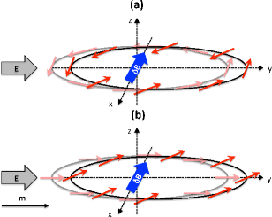
The concept of intrinsic SOT is illustrated in Fig. 1 (see also the discussion in Ref. Kurebayashi, ). Figure 1(a) represents the Fermi surface of a non-magnetic Rashba 2DEG under the application of an external electric field . At equilibrium () the spin direction (pink arrows) is tangential to the Fermi surface (grey circle) at all k-points, and the total spin density vanishes. Applying the electric field accelerates the electrons on the Fermi surface and they feel a modified spin-orbit field (thick blue arrow) around which the spin momenta (red arrows) start to precess. For a non-magnetic 2DEG, the resulting spin density vanishes while a non-zero transverse spin-current is generated by this mechanism. This is the origin of the intrinsic SHE.
Now, let us consider the case of a magnetic Rashba 2DEG in the strong ferromagnetic limit [Fig. 1(b)]. At equilibrium, the spin momenta (pink arrows) are approximately aligned along the magnetization direction (thin black arrow) for all k-points of the Fermi surface (grey circle). Under the application of an external electric field, the spin momenta (red arrows) precess around (thick blue arrow) resulting in a non-vanishing spin density. Following the convention adopted in Fig. 1(b), the electric field and equilibrium magnetization are along , the displacement of the Fermi surface produces a non-equilibrium spin-orbit field along and the spin precession around produces a spin density aligned along . The latter results in an additional torque that has a disorder-independent origin.Kurebayashi This simple picture can be extended to more complex spin-orbit coupling situation and only requires inversion symmetry breaking in the system.
III Two-dimensional Rashba ferromagnet
We first apply this formalism to a ferromagnetic 2DEG in the presence of Rashba spin-orbit coupling. rashba-1984 This system is the prototypical free-electron model for SOTs in ultra thin ferromagnets embedded between two asymmetric interfaces.manchon-prb ; Obata-prb-2008 ; garate-prb-2009 Although the actual band structure of magnetic bilayers such as Pt/Co is complex, recent first principle calculations indicate that this simple Rashba model qualitatively captures most of the relevant physics at these interfaces.haneydft This section is therefore developed mostly for pedagogical purposes in order to make the dependence on various parameters explicit. The unperturbed Hamiltonian in Eq. (1) can be rewritten as:
| (6) |
where , is the Rashba parameter and the magnetization direction is . By diagonalizing Eq. (6), the eigenvalues and eigenvectors of itinerant electrons are
| (7) | |||
| (8) | |||
| (13) |
where we have and . The velocity operator is given by . Exploiting Eqs. (II)-(5) in the weak exchange limit (), the nonequilibrium spin density reads
| (14) | ||||
| (15) | ||||
| (16) |
and in the strong exchange limit (),
| (17) | ||||
| (18) | ||||
| (19) |
In summary, the SOT field defined as , takes on the following form in the two limits:
| (20) | ||||
| (21) |
Three important facts ought to be pointed out. First, the extrinsic contributions (either intra- or interband) both give rise to an in-plane SOT field [even in magnetization direction, lying in the () plane]. The resulting extrinsic torque is then out-of-plane and odd in magnetization direction. Second, the intrinsic contribution [second term in Eqs. (III) and (21)] only produces a SOT field odd in magnetization direction. It lies perpendicular to the () plane in the strong exchange limit, see Eq. (21). This term is independent of the exchange , in sharp contrast with the ISGE-induced SOT field, while in the weak exchange limit, Eq. (III), it is second order in exchange and proportional to . The resulting intrinsic torque is in-plane in the strong exchange limit and even in magnetization direction. As will be seen in the next section, the parameters dependence displayed in Eqs. (III) and (21) is not restricted to the simple case of the Rashba model. Third, notice that in the strong exchange limit the ratio of the anti-damping-like to the field like torque is . This dependence is the inverse of what was found in Refs. pesin2012, and wang-manchon-2012, in the diffusive limit and ignoring the interband scattering, where the ratio between the two torques is governed by . A corrective anti-damping-like torque proportional to is also obtained when considering a finite spin-flip relaxation time .wang-manchon-2012 ; pesin2012
In the case of the anomalous Hall effect, related and better explored transport phenomenon, the intrinsic contribution dominates over the extrinsic contributions in the strong scattering limit.onoda ; rmp As a consequence, one is tempted to anticipate that the intrinsic contribution to the SOT discussed presently becomes important when strong momentum scattering is present (such as in disordered Pt/Co interfaces for example) and dominates over the corrections found in Refs. wang-manchon-2012, ; pesin2012, in this limit. Nevertheless, these different contributions have been derived in different limits — i.e. strongwang-manchon-2012 ; pesin2012 versus weak scattering (this work) — and should to be treated on equal footing for a rigorous comparison (e.g., see Ref. onoda, ). Such a comprehensive model is beyond the scope of the present work.
IV Dilute Magnetic Semiconductors
IV.1 Method
We now extend the previous results beyond the simple ferromagnetic 2DEG model with Rashba spin-orbit coupling. We consider a bulk three-dimensional DMS, such as (Ga,Mn)As, with a homogeneous magnetization. In order to model the SOT field of (Ga,Mn)As, we adopt a Hamiltonian including a mean-field exchange coupling between the hole spin () and the localized (-electron) magnetic moment of ionized acceptors abolfath-prb-2001 ; jungwirth-apl-2002 and a four-band strained Kohn-Luttinger Hamiltonian. The total Hamiltonian of the DMS reads
| (22) |
where is the antiferromagnetic coupling constant between hole and local moment spins for (Ga,Mn)As and is the localized Mn spin. The hole spin operator is a matrix.abolfath-prb-2001 The concentration of the ordered local Mn2+ moments is the product of that defines the doping by Mn2+ ions and inverse volume per Ga atom ( is the GaAs lattice constant). The Kohn-Luttinger Hamiltonian in Eq. (22) is expressed as luttinger56
| (23) |
This Hamiltonian applies close to the point to centro-symmetric crystals with a diamond structure and strong spin-orbit coupling in the valence bands. The Luttinger parameters for GaAs are , is the unity matrix, , , and , are the angular momentum matrices for spin . They follow the relation , and denotes cyclic permutation of the preceding term. The first term denotes the kinetic energy of the holes. The second and third terms are associated with the spin-orbit coupling of the diamond crystal. In zinc-blende crystals, such as GaAs, bulk inversion asymmetry gives rise to the so-called cubic Dresselhaus spin-orbit coupling.cubic-dresselhaus We neglect this term in the present study since there is no experimental indication that it contributes significantly to the SOT in (Ga,Mn)As.
Hamiltonian should be understood as an effective model attempting to describe the current-driven SOT in (Ga,Mn)As rather than the complete description of the electronic structure in this material. In a cubic diamond crystal, . When , dispersions following from Eq. (23) become spherically symmetric and when the spin-orbit coupling is removed completely (), Eq. (23) reduces to a parabolic model. The impact of these three degrees of approximation (parabolic model, spherical approximation and diamond crystal) on the SOT will be addressed in Section IV.2.4.
At this level of approximation the effective Hamiltonian, Eq. (23), does not break bulk inversion symmetry even though the actual crystal of the host GaAs does. Indeed, although the full model of GaAs contains additional terms that are odd in (see Tab. 6.2 in Ref. Band-Winkler, ), it is experimentally established that the SOT in (Ga,Mn)As is sensitive to the strain. We therefore assume, in line with experiments,fang-nanotech-2011 that the key inversion-breaking term is proportional to the strain. The strain Hamiltonian is given by
| (24) |
where and () are the diagonal and non-diagonal elements of the strain tensor, respectively. We assume and .
In Eq. (24), the first term () originates from the lattice mismatch between the crystal structure of the substrate and the one of (Ga,Mn)As, and produces a spin-orbit coupling with Dresselhaus symmetry linear-dresselhaus (). The second term () is the shear strain and possesses the symmetry of Rashba spin-orbit coupling rashba-1984 (). Among the different terms linear in and resulting from the inversion symmetry breaking (see Tab. C.5 in Ref. Band-Winkler, ), is the only one that acts in the manifold of heavy and light-hole states. It is worth pointing out that we consider here a large-enough system that allows us to disregard any effects arising from boundaries and confinement. In the following, we assume eVnmfang-nanotech-2011 ; chernyshov-nph-2009 and consider the lattice mismatch strain (with and ). Physical presence of the shear strain () in unpatterned (Ga,Mn)As samples is below the detection limit,Kopecky:2011_a yet it has been introduced in previous theory studies to effectively model the in-plane uniaxial anisotropy observed in experiments.Zemen:2009_a Calculations with nonzero are explicitly pointed out in the following.
The SOT field is evaluated once the energies and eigenfunctions implied by the Hamiltonian in Eq. (22) are numerically calculated and the current-driven spin density is determined using Eq. (2). In general, the SOT field can be decomposed as
| (25) |
where vectors have unit length, , , the subscript “” has been removed for simplicity, and the direction of (whose length is also set equal to one) should be chosen depending on the system. For example, we find for the Rashba 2DEG. On the other hand, in (Ga,Mn)As with growth strain () as described by Eq. (22) and current flowing along the crystallographic direction. Our results presented below always assume pointing in the positive direction.
In the following, we disregard the component of the SOT field which is parallel to the magnetization () since it does not exert any torque on it. The two remaining components in Eq. (25) turn out to produce, in (Ga,Mn)As, the anti-damping-like SOT in the case of which is due to intrinsic interband mixing (of impurity-independent origin) and a combination of anti-damping-like and field-like extrinsic SOT in the case of which depends through on the disorder strength. The angular dependence of the two components, , reflects the details of the band structure as discussed in Sec. IV.2.4.
IV.2 Numerical Results
For all the calculations presented in this section, the electric field V/nm is assumed to be applied along the -axis and we varied the hole concentration between 0.3 nm-3 and 1 nm-3. This corresponds, respectively, to a Fermi energy between 200 and 450 meV. Except for Sec. IV.2.4, magnetization always lies along the -axis ().
IV.2.1 Intrinsic Versus Extrinsic Spin-Orbit Torques
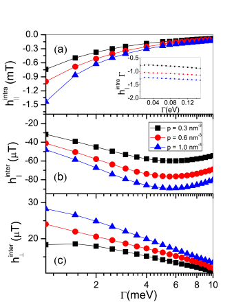
We first investigate the impact of impurity scattering on the intraband and interband contributions to the SOT fields. Figure 2 displays the SOT field as a function of the energy broadening for different values of hole concentrations. Although is of the order of hundreds of meV in realistic (Ga,Mn)As, we choose meV so as to be able to compare these results with the analytical ones obtained in Sec. III for the ferromagnetic Rashba 2DEG which are valid in the small limit.
The intraband contribution to the SOT field, , is inversely proportional to for all hole densities as it is seen in Fig. 2(a). This agrees with Eq. (II) and also Eqs. (14) and (17) model for the ferromagnetic Rashba 2DEG. No component exists. On the other hand, the interband part () of Eq. (2) contributes both to and which is shown in Figs. 2(b) and (c). The former is a correction to the intraband SOT field and it scales in the weak scattering limit. It tends to counteract the intraband contribution, as it is the case in the ferromagnetic Rashba 2DEG described by Eqs. (III) and (21). The out-of-plane component converges to a finite value when vanishes, indicating the intrinsic character of this part of the SOT field. These results are consistent with the analytical solutions obtained in Eqs. (17)-(19) in the ferromagnetic Rashba 2DEG and weak scattering limit. It is worth noticing that this dependence on spectral broadening holds over a wide range of in the case of intraband contribution [see inset in Fig. 2(a)], while it breaks down already for equal to few meV for the interband contributions.
IV.2.2 Ferromagnetic splitting
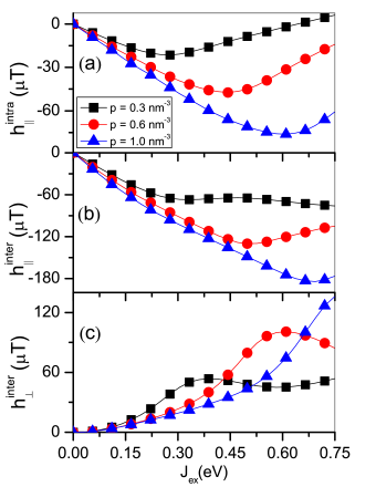
The band structure of (Ga,Mn)As changes with the Mn doping that would, in the absence of the SOI, lead to a rigid mutual shift of the majority- and minority-spin bands. Such ferromagnetic splitting would be proportional to and we can distinguish two limiting situations in a system where the SOI is present: and . In view of the analytical results presented in Sec. III, it is meaningful to take in the Rashba 2D system. For each component of the non-equilibrium spin-density , , , there is a transition between different types of behaviour in the two limits. For example, the out-of-plane component of the SOT field changes from the behaviour in the limit implied by Eq. (16) into a -independent behaviour in the opposite limit implied by Eq. (19). We checked that this transition occurs also in the numerical calculations across a range of values.
Contrary to the Rashba 2D system, the situation is more complicated in (Ga,Mn)As because of the additional SOI terms in Eq. (23). Due to their mutual competition, it is not obvious what should be taken for the effective spin-orbit strength . Looking at the -dependence of the individual SOT field components in Fig. 3, we nevertheless recognize similarities to the limit behaviour of the Rashba 2D system. To some extent, this is a surprising finding since the disorder broadening used for calculations in Fig. 3 is quite large ( meV), better corresponding to realistic (Ga,Mn)As samples but further away from the assumptions used to derive the analytical results presented in Sec. III. When is small, both and are proportional to as seen in Eqs. (14) and (15), respectively. On the other hand, in the bottom panel of Fig. 3 which is reminiscent of Eq. (16). No similarities to the Rashba 2D system behaviour of the opposite limit () are found in our calculations for (Ga,Mn)As.
IV.2.3 Hole concentration
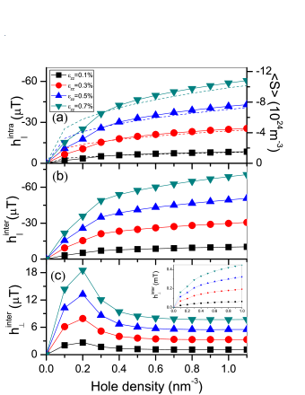
We display in Fig. 4 the SOT field as a function of the hole density for different magnitudes of the lattice-mismatch strain . First of all, we notice that the SOT field components increase linearly with the strain. Second, increase of the hole concentration results in an increase in the in-plane SOT field approximatively following a law, as shown in Figs. 4(a) and (b). This is consistent with Eq. (17) in Ref. bernevig, in case of the intraband component. Interestingly, the in-plane interband SOT field shows a similar tendency [Fig. 4(b)], while the out-of-plane interband SOT field has a different dependence on . This anti-damping-like SOT field in Fig. 4(c) first increases with the hole concentration in the low hole density regime and later decreases towards a saturated value. This could be because of the competition of the different SOI types in (Ga,Mn)As as noticed by Kurebayashi et al. Kurebayashi . Indeed, when the diamond-lattice spin-orbit coupling is absent (), the out-of-plane interband SOT field increases with the hole concentration following the same law as for the in-plane field [see inset of Fig. 4(c)]. For a four-band Luttinger model that includes band warping (), the competition between the diamond spin-orbit coupling and the strain-induced spin-orbit coupling results in a reduction of , as shown in Fig. 4 of Ref. Kurebayashi, . The reason why the competition between the diamond spin-orbit coupling and the strain-induced spin-orbit coupling leads to the deviation from the analytical formula only in the case of the and not for remains to be explored in detail.
At this point, we remark that shear strain in Eq. (24) leads to comparable to values shown in Fig. 4(a) when the value of is comparable to used in Fig. 4. However, since the relevant values of in unpatterned epilayers are typically order-of-magnitude lowerZemen:2009_a than those of , we can typically expect an order-of-magnitude smaller originating from the -term in Eq. (24) as compared to the -term.
IV.2.4 Impact of the Band Structure
The total DMS Hamiltonian given in Eq. (22) has both centro-symmetric and non-centro-symmetric components given by Eqs. (23) and (24), respectively. As discussed in the previous section, the spin-orbit coupling of the centro-symmetric component of the Hamiltonian [i.e., the terms in Eq. (23) proportional to and ] affects also the SOT field, notably their dependence on the magnetization direction [recall the definition of and below Eq. (6)]. Apart from the findings of Ref. Kurebayashi, discussed above, it was shown in Ref. Hang-apl-2013, that the shape of the Fermi surface has a strong impact on the angular dependence of the intraband SOT field .
We now systematically explore the influence of the spin-orbit coupling of the diamond crystal on the different components of the SOT field, i.e. , and . The centro-symmetric component of the total DMS Hamiltonian, Eq. (23), accounts for the spin-orbit coupling through a set of the Luttinger parameters, . By tuning these three parameters, one can modify the form of the centro-symmetric spin-orbit coupling. We model three distinct cases: (i) the parabolic approximation where no centro-symmetric spin-orbit coupling is present (), (ii) the spherical approximation where the centro-symmetric spin-orbit coupling is turned on but spherical symmetry is retained () and (iii) the diamond crystal where both cubic symmetry and centro-symmetric spin-orbit coupling are accounted for (). This approach allows us to identify the role of the last two terms of Eq. (23) on the SOT fields. In Fig. 5, we show the angular dependence of the different contributions to the SOT field for the spin-orbit coupling induced by the lattice-mismatch strain in the context of models (i)–(iii). The magnetization lies in the () plane () and its direction is given by the azimuthal angle .
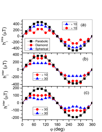
As expected from the symmetry of the term in Eq. (24), the three components of the SOT field have a dependence of the form in the parabolic model ( symbols in Fig. 5). When diamond-lattice spin-orbit coupling is switched on but the spherical approximation is assumed, the interband SOT fields [ symbols in Figs. 5(b) and (c)] deviate from this dependence, while the angular dependence of the intraband term remains unaffected [ symbols in Fig. 5(a)]. Furthermore, the magnitudes of interband and intraband SOT fields strongly decrease. This is a manifestation of the competition between the strain-induced terms in Eq. (24) with the centro-symmetric Luttinger spin-orbit terms in Eq. (23).Kurebayashi
When the spherical approximation is lifted () electronic bands become warped, especially those of the heavy holes. This results into an increase of the interband SOT fields and an additional angular dependence shown by symbols in Fig. 5. Microscopically, the latter effect is caused by the distorted spin textures on the Fermi surface. The influence of the centro-symmetric spin-orbit field on the spin torque in GaMnAs has also been identified by Haney et al.haneyprl in DMS spin-valves.
V Summary and conclusion
We have studied the intraband and interband SOT fields using Kubo formula, in the prototypical case of a ferromagnetic 2DEG with Rashba spin-orbit coupling, as well as in a three-dimensional DMS modelled by a kinetic-exchange Kohn-Luttinger Hamiltonian. For the latter, parameters pertaining to (Ga,Mn)As were used. In the limit of low doping concentration and weak exchange coupling, we find similarities between the two systems, demonstrating that the general trends of the intrinsic and extrinsic SOT fields can be understood analytically using the Rashba 2DEG in the weak scattering limit. Nevertheless, the numerical analysis of the three-dimensional DMS system also unravels the complex interplay between the different types of spin-orbit coupling (centro-symmetric and non-centro-symmetric) involved in realistic systems resulting in complex dependences of the SOT fields on the magnetization direction as well as significant differences from the Rashba 2DEG model. The contribution of interband mixing to the SOT presents an outstanding opportunity to explain the emergence of large anti-damping-like torques that cannot be readily attributed to spin Hall effect, offering an interesting platform to interpret recent puzzling results.jamali ; mellnik
Acknowledgements.
I.G. acknowledges financial support from Canadian NSERC. H.L., X.W., F.D., and A.M. were supported by the King Abdullah University of Science and Technology (KAUST). H.G. and J.S. were supported by the NSF Grant No. DMR-1105512, and the Alexander Von Humboldt Foundation. Work at FZU was supported by the Grant Agency of the Czech Republic Grant No. 14-37427G and K.V. moreover acknowledges sustained support of L., Grant No. 15-13436S and Ministry of Education of the Czech Republic Grant No. LM2011026. We thank J. Železný for his inspirational suggestions and A.H. MacDonald for discussions at initial stages of the project.References
- (1) J. Slonczewski, J. Magn. Magn. Mater. 159, L1 (1996).
- (2) L. Berger, Phys. Rev. B 54, 9353 (1996).
- (3) D. C. Ralph and M. D. Stiles, J. Magn. Magn. Mater. 320, 1190 (2008), and references therein.
- (4) C. Chappert, A. Fert and F. N. Van Dau, Nature Mate. 6, 813 (2007).
- (5) A. Brataas, A. D. Kent and H. Ohno, Nature Mater. 11, 372 (2012).
- (6) B. A. Bernevig and O. Vafek, Phys. Rev. B 72 033203 (2005).
- (7) A. Manchon and S. Zhang, Phys. Rev. B 78, 212405 (2008); Phys. Rev. B 79, 212405 (2009).
- (8) K. Obata and G. Tatara, Phys. Rev. B.77, 214429 (2008).
- (9) J. Železný et al., Phys. Rev. Lett. 113, 157201 (2014).
- (10) I. Garate and A. H. MacDonald, Phys. Rev. B 80, 134403 (2009); A. Matos-Abiague and R. L. Rodriguez-Suarez, Phys. Rev. B 80, 094424 (2009); S. G. Tan, M. B. A. Jalil, and X-J. Liu, ArXiV: 0705.3502v1 (2007).
- (11) D. A. Pesin and A. H. MacDonald, Phys. Rev. B 86 014416 (2012).
- (12) E. van der Bijl and R. A. Duine, Phys. Rev. B 86, 094406 (2012).
- (13) K.-W. Kim, S.-M. Seo, J. Ryu, K.-J. Lee, and H.-W. Lee, Phys. Rev. B 85 180404(R) (2012).
- (14) X. Wang and A. Manchon, Phys. Rev. Lett. 108, 117201 (2012).
- (15) H. Li, X. Wang, F. Dogan, and A. Manchon, Appl. Phys. Lett. 102, 192411 (2013).
- (16) A. Chernyshov, M. Overby, X. Liu, J. K. Furdyna, Y. Lyanda-Geller, and L. P. Rokhinson, Nature Phys. 5, 656 (2009).
- (17) M. Endo, F. Matsukura, and H. Ohno, Appl. Phys. Lett. 97, 222501 (2010).
- (18) D. Fang, H. Kurebayashi, J. Wunderlich, K. Výborný, L. P. Zârbo, R. P. Campion, A. Casiraghi, B. L. Gallagher, T. Jungwirth, and A. J. Ferguson, Nature Nanotech. 6, 413 (2011).
- (19) I. M. Miron et al. Nature Mate. 9, 230 (2010); U. H. Pi et al. Appl. Phys. Lett. 97, 162507 (2010); T. Suzuki, S. Fukami, N. Ishiwata, M. Yamanouchi, S. Ikeda, N. Kasai, and H. Ohno, Appl. Phys. Lett. 98, 142505 (2011).
- (20) I. M. Miron, et al. Nature (London) 476, 189 (2011).
- (21) L. Liu et al. Phys. Rev. Lett. 109, 096602 (2012); L. Liu et al. Science 336, 555 (2012).
- (22) J. Kim, J. Sinha, M. Hayashi, M. Yamanouchi, S. Fukami, T. Suzuki, S. Mitani and H. Ohno, Nat. Mater. 12, 240 (2013).
- (23) K. Garello, I. M. Miron, C. O. Avci, F. Freimuth, Y. Mokrousov, S. Blügel, S. Auffret, O. Boulle, G. Gaudin, and P. Gambardella, Nature Nanotechn. 8, 587 (2013).
- (24) X. Fan, J. Wu, Y. Chen, M. J. Jerry, H. Zhang and J. Q. Xiao, Nat. Comm. 4, 1799 (2013).
- (25) M. Jamali, K. Narayanapillai, X. Qiu, L. M. Loong, A. Manchon, and H. Yang, Phys. Rev. Lett. 111, 246602 (2013).
- (26) A. R. Mellnik, J. S. Lee, A. Richardella, J. L. Grab, P. J. Mintun, M. H. Fischer, A. Vaezi, A. Manchon, E.-A. Kim, N. Samarth, and D. C. Ralph, arXiv:1402.1124 (2014); Y. Fan, P. Upadhyaya, X. Kou, M. Lang, S. Takei, Z. Wang, J. Tang, L. He, L.-T. Chang, M. Montazeri, G. Yu, W. Jiang, T. Nie, R. N. Schwartz, Y. Tserkovnyak and K. L.Wang, Nature Materials 13, 699 (2014).
- (27) Calling an anti-damping-like torque is inspired by the Gilbert-damping term introduced into the Landau-Lifshitz equation. Whether this torque indeed counteracts the damping of magnetization precession, depends on the direction of relative to the external magnetic field and this in turn depends on the details of the system in question. Terminology varies in literature, e.g. Ref. haneyboltz, refer to this kind of torque as to a dampinglike one while the authors of Ref. Kurebayashi, call it anti-damping-like.
- (28) To begin with, it is convenient to use the concept of independent of the magnetization direction . In some systems explored in literature, however, does to some extent depend on and in principle, this dependence does not even have to be weak. The essence of the distinction between field-like and anti-damping-like SOT fields relies on the requirement that is an even function of (see the second reference of [haneydft, ]). Some examples of are discussed in Sec. III below Eq. (25).
- (29) For a review on ISGE, see V.V. Belkov and S. D. Ganichev, Semicond. Sci. Technol. 23, 114003 (2008) or chapter II.D of Ref. Sinova:2014_a, .
- (30) P. M. Haney, H. W. Lee, K. -J. Lee, A. Manchon, and M. D. Stiles, Phys. Rev. B 87, 174411 (2013).
- (31) P. M. Haney, H. W. Lee, K. -J. Lee, A. Manchon, and M. D. Stiles, Phys. Rev. B 88, 214417 (2013); F. Freimuth, S. Blügel, and Y. Mokrousov, Phys. Rev. B 90, 174423 (2014).
- (32) H. Kurebayashi, J. Sinova, D. Fang, A. C. Irvine, J. Wunderlich, V. Novak, R. P. Campion, B. L. Gallagher, E. K. Vehstedt, L. P. Zârbo, K. Vyborny, A. J. Ferguson, and T. Jungwirth, Nature Nanotech. 9, 211 (2014).
- (33) J. Sinova, D. Culcer, Q. Niu, N. A. Sinitsyn, T. Jungwirth, and A. H. MacDonald, Phys. Rev. Lett. 92, 126603 (2004).
- (34) S. Murakami, N. Nagaosa and S.–C. Zhang, Science 301, 1348 (2003).
- (35) T. Jungwirth, J. Sinova, J. Mašek, J. Kučera, A.H. MacDonald, Rev. Mod. Phys. 78, 809 (2006).
- (36) The current-spin response analogy to Eq. (B6) in Ref. Tesarova:2014_a, is the key to the link between Eq. (2) and the sum of Eqs. (II,4,5).
- (37) N. Tesařová et al., Phys. Rev. B 89, 085203 (2014).
- (38) J. Sinova, S.O. Valenzuela, J. Wunderlich, C.H. Back, and T. Jungwirth, arxiv:1411.3249 (2014).
- (39) see e.g. N. Nagaosa, J. Sinova, S. Onoda, A. H. MacDonald, and N. P. Ong, Rev. Mod. Phys. 82, 1539 (2010).
- (40) Y. A. Bychkov and E. I. Rashba, J. Phys. C: Solid State Phys. 17, 6039 (1984).
- (41) S. Onoda, N. Sugimoto, and N. Nagaosa, Phys. Rev. Lett. 97, 126602 (2006).
- (42) T. Jungwirth, M. Abolfath, J. Sinova, J. Kučera, and A. H. MacDonald, Appl. Phys. Lett. 81, 4029 (2002).
- (43) M. Abolfath, T. Jungwirth, J. Brum, and A. H. MacDonald, Phys. Rev. B 63, 054418 (2001).
- (44) J. M. Luttinger, Phys. Rev. 102, 1030 (1956); J. M. Luttinger and W. Kohn, Phys. Rev. 97, 869 (1955).
- (45) G. Dresselhaus, Phys. Rev. 100, 580 (1955).
- (46) R. Winkler, Spin-orbit Coupling Effects in Two-Dimensional Electron and Hole Systems (Springer, 2003).
- (47) G. L. Bir and G. E. Pikus, Symmetry and Strain-Induced Effects in Semiconductors (Wiley, 1974).
- (48) M. Kopecký et al., Phys. Rev. B 83, 235324 (2011).
- (49) J. Zemen, J. Kučera, K. Olejník, and T. Jungwirth, Phys. Rev. B 80, 155203 (2009).
- (50) P. M. Haney and M. D. Stiles, Phys. Rev. Lett. 105, 126602 (2010).