Light scattering in pseudo-passive media with uniformly balanced gain and loss
Abstract
We introduce a class of metamaterials with uniformly balanced gain and loss associated with complex permittivity and permeability constants. The refractive index of such a balanced pseudo-passive metamaterial is real. An unbounded uniform pseudo-passive medium has transport characteristics similar to those of its truly passive and lossless counterpart with the same real refractive index. However, bounded pseudo-passive samples show some unexpected scattering features which can be further emphasized by including such elements in a photonic structure.
pacs:
42.82.Et, 42.25.Bs, 11.30.ErIn the last decade we have witnessed unprecedented advancements in realizing artificial materials which are specifically designed to exhibit features not found in nature. In the electromagnetic domain, such metamaterials are using their structural composition in order to obtain access of all four quadrants in the real plane. Various exotic phenomena ranging from negative refraction to electromagnetic cloaking and super-lensing have been actively pursued Y87 ; JMW95 ; BKR97 ; K03 ; V68 ; P00 ; SSS01 ; SCCYSDK05 . While these opportunities have been extraordinary, optical materials exhibiting exotic values of permittivity and/or permeability are often prohibitively lossy. This is especially true for composite optical meta-materials. A natural solution to the problem is to add a gain component and, thereby, to offset the losses. A pathway to achieve this goal has been recently proposed in Ref. MGCM08 , and subsequently explored in a number of publications GSDMVASC09 ; RMGCSK10 ; CJHYWJLWX14 ; RBMOCP12 ; FWMWZ14 ; KGM08 ; L09 ; L10 ; CGS11 ; LPRS13 ; RMBNOCP13 ; HMHCK14 ; CSGAE13 ; POLMGLFNBY14 ; LFLVEK14 ; NBRMCK14 ; RLKKKV12 ; RCKVK12 ; LREKCC11 . This proposal capitalizes on the notion of Parity-Time () symmetry by utilizing balanced gain and loss elements which are judiciously distributed in space such that the complex index of refraction satisfies the relation . This research line gave many intriguing transport properties like double refraction, unidirectional invisibility, asymmetric transport, CPA/ Lasers etc.
An alternative approach is to compensate the losses with gain while preserving the uniformity of the medium. This can be done simply by doping the lossy medium with active elements (dies), so that the doped material would have a real refractive index The question, however, is whether such a balanced loss/gain medium with real and uniform refractive index will automatically behave as a regular passive lossless medium. This is certainly true if the permeability is real, in which case the negative contribution to from gain will simply offset the positive contribution from absorption gain1 ; gain2 ; gain3 .
In this Letter we will concern with a different scenario where both and are complex i.e. . A typical example is plasmonic metamaterials where the effective permeability is associated with the electric current induced in tiny ring resonators by oscillating magnetic fields. If both and are complex, a real-value refractive index can only be realized if (where is real), which is quite possible in media with gain. In this case and thus one expects that an unbounded medium consisting of such material will support traveling waves as its lossless passive counterpart with the same index of refraction. We will therefore refer to media with real refractive index and complex and as pseudo-passive (PP) media. Surprisingly, once a pseudo-passive medium is confined in space, its scattering properties are completely different than the ones of its passive counterpart. The difference becomes even more striking when a pseudo-passive material is a component of a photonic structure. For example, the Fabry-Perrot resonances of a Bragg grating that contains pseudo-passive composite layers display sub- or super unitary transmittance at the band-edges. Remarkably, under different circumstances, the same pseudo-passive material can act as a perfect absorber, or it can trigger lasing instability.
The scattering properties of a pseudo-passive structure are understood better by considering monochromatic wave propagation in an one-dimensional scattering set-up. In this case, the steady state (TE) electric field is scalar and satisfies the Helmholtz equation
| (1) |
where is the frequency of the field and is the speed of light in vacuum while the spatially dependent index of refraction is considered real for any position . In the case that the pseudo-passive medium is extended over the whole space, Eq. (1) admits wave solutions of the form where is the free space wavevector. These solutions are identical to the ones found at an infinite lossless passive medium with index of refraction .
These similarities between a PP medium and a lossless passive medium cease to exist once we turn to the analysis of the associated scattering problem involving bounded structures. For simplicity we assume that the domain which contains the pseudo-passive structure extends in the interval . We further assume that the scatterer is embedded in a homogeneous medium with uniform index of refraction which, for simplicity, we consider it to be equal to unity i.e. . The solution of Eq. (1) at the left of the scattering sample is while on its right is . We can relate the amplitudes of forward and backward propagating waves on the left of the scattering domain with the amplitudes on its right via the transfer matrix
| (2) |
In case of composite structures the transfer matrix (TM) is a product of transfer matrices associated with each individual composite element i.e. . The individual TM’s are evaluated by imposing the appropriate boundary conditions at the interface between consequent layers and of the structure. For a TE mode we have that the field itself is continuous while its spatial derivative satisfies the relation:
| (3) |
The transmission and reflection amplitudes for left and right incident waves are defined as and . They are written in terms of the TM elements as
| (4) |
Furthermore, we can show that and thus . The associated transmittance and reflectances are and .
An alternative formulation of the scattering process is provided by the scattering matrix which connects incoming and outgoing wave amplitudes i.e.
| (5) |
The scattering matrix can be written in terms of the -matrix elements as
| (6) |
and is useful for the theoretical analysis of lasing instabilities and perfect absorption. Below we provide some examples which illustrate the anomalous scattering properties of a bounded structure that includes a PP-medium.
We start our analysis with the investigation of the transport properties of a single PP-layer. The associated TM that describes the scattering process is
| (7) |
where the matrices and are defined as
| (8) |
Using Eq. (4) we evaluate the transmission and reflection amplitudes of a single PP-layer:
| (9) | |||||
The subindex indicates that we refer to the constituents of the PP-layer and is its complex admittance.
The Fabry-Perrot resonances are defined by the requirements and and occur at frequencies for which . This implies perfect resonant transmission with no losses and no gain, regardless of the value of and despite the fact that the constituents are complex. Let us now calculate the transport characteristics of the PP-layer at . For example, at the middle between two consecutive Fabry-Perrot resonances, i.e. when , we have:
| (10) | |||||
Remarkably, the off-resonance value of is always negative and independent of the slab thickness indicating that its origin is associated with surface scattering rather than bulk scattering precesses. In fact, it is straightforward to show that a PP-layer will result in amplification , for any frequency , irrespective of the sign of .
Next we consider the transport properties of a lossless Bragg grating (BG) with one PP-defect layer. We assume, without loss of generality, that . Before going on with our analysis we recall that a lossless passive defect layer supports a resonant defect mode with a frequency lying inside the photonic band gap of the BG. This resonance mode is localized in the vicinity of the defect layer and decays exponentially away from the defect. Near , the entire composite structure displays a strong resonant transmission with (and thus ) due to the excitation of the localized mode.
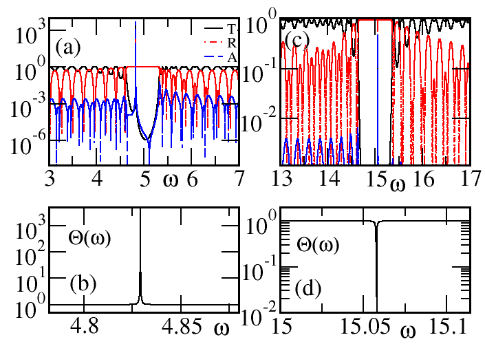
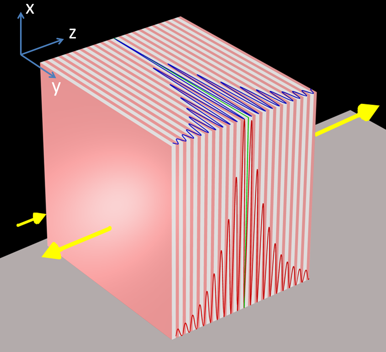
A completely different scenario emerges when the defect layer consists of a PP-medium. We find that the resonance localized mode has transmittance and reflectance values which are larger (smaller) that unity in distinct contrast to the case of lossless defect layers. The super (sub)-unitary transmission/reflection is related with the distribution of the electro-magnetic field around the PP-defect. Let us consider the case for which the electric field takes its maximum value (anti-nodal point) at the position of the defect layer (see Fig. 1). Obviously the associated magnetic field will be having a nodal point at the defect layer. Then, an estimation of the absorbed energy, due to the PP-layer, gives and thus . The transmission and reflection spectrum are shown in Fig. 2a and confirm the previous expectations.
The opposite scenario is observed in the case that the magnetic field has a maximum in the domain around the defect layer. In this case (we recall that ) and thus we have attenuation of the incident light.
The amplification/attenuation mechanism is better investigated by introducing the overall amplification/absorption coefficient defined as the ratio of the total intensity of outgoing to incoming waves:
| (11) |
The above expression can be written in the following form
| (12) |
where we have used the fact that . The case indicates that an overall amplification has been achieved at the system. The opposite limit of corresponds to attenuation. The two extreme cases of and indicate that the system has reached a lasing instability or behaves as a coherent perfect absorber (CPA) respectively. The condition for the former case is which is satisfied for some values and . In fact, the complex zeros of correspond to the poles of the scattering matrix , see Eq. (6). If they lie at the lower part of the complex- plane due to causality. As increases the poles move towards the real axis and at a critical value one of these poles becomes real , thus signifying the transition to a lasing action. We have confirmed in Fig. 2b that the singularity in corresponds to the lasing point as it is calculated from the analysis of the poles of the associated scattering matrix.
The other limiting case of CPA is achieved when the two terms in the numerator of Eq. (12) become simultaneously zero i.e. when and . These two relations are simultaneously satisfied when (recall that ). The CPA frequency is evaluated from the condition (the frequencies for which are excluded since they correspond to lasing action). It should be stressed that a CPA requires coherent incident fields which satisfy an appropriate phase and amplitude relationship . An example of a CPA is shown in Fig. 2d.
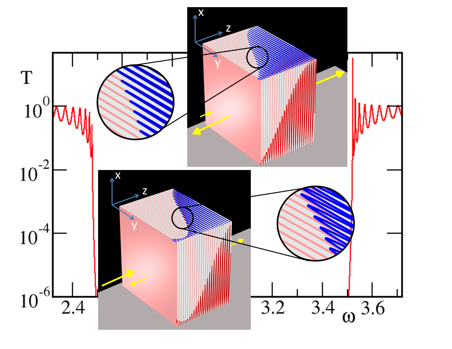
The above super/sub-unitary scattering features become more pronounced when one of the composite layers of the Bragg grating is substituted by a pseudo-passive medium. Specifically, the Fabry-Perrot (FP) resonances which are closer to the band edges will correspond to photons with small group velocities. Therefore each individual photon at this frequency resides in the PP-layers for a long time. This long time interaction with the PP-medium leads to strong amplification/attenuation features. The magnitude of the enhancement/suppression is a growing function of the total thickness of the stack, as opposed to the case of a uniform pseudo -passive slab. In Fig. 3 we show a typical transmission spectrum of such composite structure.
In the particular case of a FP resonance close to a photonic band edge of a BG, consisting of two layers A and B, the field inside the periodic structure is a superposition of the forward and backward Bloch waves with Bloch wave number close to either the middle of the Brillouin zone, or to its boundary. In either case, the middle of each individual layer coincides with the node or the antinode of the respective standing wave inside this particular uniform layer. The nodes (antinodes) of oscillating electric field coincide with the antinodes (nodes) of oscillating magnetic field and vice versa.
At the same time, if the lower edge of a photonic band gap has electric field node (magnetic field antinode) in the middle of each A-layer, then the upper edge of the same photonic band gap has electric field antinode (magnetic field node) in the middle of each A-layer Jbook . As a consequence, Fabry-Perrot resonances close to neighboring photonic band edges will have different dominating components - electric or magnetic - of the oscillating field inside a particular layer.
In our example in Fig. 3 the A-layers consists of a PP-medium with negative and positive , which means that the Fabry-Perrot resonances with the dominant electric field component in the A-layers will be enhanced, while the resonances with dominant magnetic field component in the A-layers will be suppressed. This is exactly what we see in Fig. 3, where the resonant transmission at every other photonic band edge is enhanced (suppressed).
In conclusion, we have introduced a class of pseudo-passive metamaterials for which the losses are balanced by gain in a way that the index of refraction is real and uniform throughout the medium. Although the light propagation in an unbounded pseudo-passive medium has the same characteristics as in a passive lossless medium with the same index of refraction, their scattering properties differ dramatically. When such media are incorporated in a photonic structure, it can lead to super/sub-unity transmittance/reflectance indicating strong absorption and amplification mechanisms for the total structure. In many occasions these effects can turn to a coherent perfect absorption of incident waves or to lasing instabilities. It will be interesting to investigate the realization of these phenomena under vectorial conditions and in higher dimensions.
Acknowledgment - This work was partially supported by an AFOSR MURI grant FA9550-14-1-0037, by a LRIR-09RY04COR, and by a NSF ECCS-1128571 grant.
References
- (1) E. Yablonovitch, Phys. Rev. Lett. 58, 2059 (1987).
- (2) J. D. Joannopoulos, R. D. Meade, and J. N. Winn, Photonic Crystals (Princeton Press, Princeton, NJ, 1995).
- (3) T. A. Birks, J. C. Knight, and P. S. J. Russell, Opt. Lett. 22, 961-963 (1997).
- (4) J. C. Knight, Nature 424, 847 (2003).
- (5) V. G. Veselago, Sov. Phys. Usp. 10, 509 (1968).
- (6) J. B. Pendry, Phys. Rev. Lett. 85, 3966 (2000).
- (7) R. A. Shelby, D. R. Smith, and S. Schultz, Science 292, 77 (2001).
- (8) V. M. Shalaev, W. Cai, U. K. Chettiar, H. Yuan, A. K. Sarychev, V. P. Drachev, and A. V. Kildishev, Opt. Lett. 30, 3356 (2005).
- (9) R. El-Ganainy, K. G. Makris, D. N., Christodoulides, and Z. H. Musslimani, Opt. Lett. 32, 2632 (2007); K. G. Makris, R. El-Ganainy, D. N. Christodoulides, and Z. H. Musslimani, Phys. Rev. Lett. 100, 103904 (2008).
- (10) A. Guo, G. J. Salamo, D. Duchesne, R. Morandotti, M. Volatier-Ravat, V. Aimez, G. A. Siviloglou, and D. N. Christodoulides, Phys. Rev. Lett. 103, 093902 (2009).
- (11) C. E. Rüter, K. G. Makris, R. El-Ganainy, D. N. Christodoulides, M. Segev, and D. Kip, Nat. Phys. 6, 192 (2010).
- (12) L. Chang, X. Jiang, S. Hua, C. Yang, J. Wen, L. Jiang, G. Li, G. Wang, M. Xiao, Nature Photonics 8, 524–529 (2014)
- (13) A. Regensburger, C. Bersch, M.A. Miri, G. Onishchukov, D. N. Christodoulides, and U. Peschel, Nature 488, 167-171 (2012).
- (14) Liang Feng, Zi Jing Wong, Ren-Min Ma, Yuan Wang, Xiang Zhang, Science DOI: 10.1126/science.1258479 (2014)
- (15) S. Klaiman, U. Günther, and N. Moiseyev, Phys. Rev. Lett. 101, 080402 (2008).
- (16) S. Longhi, Phys. Rev. Lett. 103, 123601 (2009); Phys. Rev. B 80, 235102 (2009); S. Longhi, Phys. Rev. Lett. 105, 013903 (2010).
- (17) S. Longhi, Phys. Rev. A 82, 031801 (2010).
- (18) Y. D. Chong, L. Ge, A. D. Stone, Phys. Rev. Lett. 106, 093902 (2011).
- (19) Y. Lumer, Y. Plotnik, M. C. Rechtsman, M. Segev, Phys. Rev. Lett. 111, 263901 (2013).
- (20) A. Regensburger, M-A Miri, C. Bersch, J. Nager, G. Onishchukov, D. N. Christodoulides, U. Peschel Phys. Rev. Lett. 110, 223902 (2013).
- (21) H. Hodaei, M-A Miri, M. Heinrich, D. N. Christodoulides, M. Khajavikhan, Science DOI: 10.1126/science.1258480 (2014).
- (22) G. Castaldi, S. Savoia, V. Galdi, A. Alu, and N. Engheta, Phys. Rev. Lett. 110, 173901 (2013).
- (23) B. Peng, S. K. Ozdemir, F. Lei, F. Monifi, M. Gianfreda, G. Lu Long, S. Fan, F. Nori, C. M. Bender, L. Yang, Nature Physics 10, 394 (2014).
- (24) J. M. Lee, S. Factor, Z. Lin, I. Vitebskiy, F. M. Ellis, T. Kottos, Phys. Rev. Lett. 112, 253902 (2014)
- (25) F. Nazari, N. Bender, H. Ramezani, M. K.Moravvej-Farshi, D. N. Christodoulides, and T. Kottos, Optics Express 22, 9574 (2014); N. Bender, S. Factor, J. D. Bodyfelt, H. Ramezani, D. N. Christodoulides, F. M. Ellis, T. Kottos, Phys. Rev. Lett. 110, 234101 (2013); H. Ramezani, T. Kottos, R. El-Ganainy, D. N. Christodoulides, Phys. Rev. A 82, 043803 (2010)
- (26) H. Ramezani, Z. Lin, S. Kalish, T. Kottos, V. Kovanis, I. Vitebskiy, Optics Express 20, 26200 (2012)
- (27) H. Ramezani, D. N. Christodoulides, V. Kovanis, I. Vitebskiy, and T. Kottos, Phys. Rev. Lett. 109, 033902 (2012)
- (28) Z. Lin, H. Ramezani, T. Eichelkraut, T. Kottos, H. Cao, D. N. Christodoulides, Phys. Rev. Lett. 106, 213901 (2011)
- (29) M. A. Noginov et al., Opt. Lett. 31, 3022 (2006); S. A. Ramakrishna, J. B. Pendry, Phys. Rev. B 67, 201101 (2003); T. A. Klar, A. V. Kildisher, V. P. Drachev, V. M. Shalaev, IEEE J. Sel. Top. Quantum Electron. 12, 1106 (2006); A. K. Sarychev, G. Tartakovsky, Phys. Rev. B 75, 085436 (2007)
- (30) S. Xiao, V. P. Drachev, A. V. Kildishev, X. Ni, U. K. Chettiar, H-K Yuan, V. M. Shalaev, Nature 466, 5 (2010).
- (31) C. M. Soukoulis, M. Wegener, Nature Photonics 5, 523 (2011)
- (32) In this case the super/sub unitary values of transmittance and reflectance can be achieved for even smaller values of since now the photons can interact for larger times with the PP- media which are distributed all over the grating.
- (33) J. Joannopoulos, S. Johnson, J. Winn, and R. Meade ”Photonic Crystals: Molding the Flow of Light”, Princeton University Press (2008).