Gate controlled resonant widths in double-bend waveguides: Bound states in the continuum
Abstract
We consider quantum transmission through double-bend - and -shaped waveguides controlled by the finger gate potential. Using the effective non-Hermitian Hamiltonian approach we explain the resonances in transmission. We show a difference in transmission in the short waveguides that is the result of different chirality in and waveguides. We show that the potential selectively affects the resonant widths resulting in the occurrence of bound states in the continuum.
pacs:
03.65.Nk, 05.60.Gg, 73.23.Ad, 73.21.LaI introduction
The effects of bend discontinuities on the transmission in double-bend quantum waveguides have been in the focus of researches for long time Weisshaar ; Wu ; Vacek ; Wang ; Mekis ; Carini ; Shi ; Ming . A Fano resonance was shown owing to the presence of a single bend Sols ; Shi ; Ming . The resonant picture complicates in the double-bend waveguides with the resonance widths and positions dependent on the distance between bends Goodnick ; Kawamura . We believe that these resonances still are not properly understood. One of the aims of the present paper is to give a comprehensive description of resonant effects in double-bend quantum waveguides using the effective Hamiltonian approach Sokolov ; Ingrid ; Stockmann ; Alhasid ; Pichugin ; SR . The central goal is however to show that the finger gate potential selectively affects resonant widths resulting in the occurrence of zero width resonances. That gives rise to trapping of an electron between the bends or bound state in the continuum (BSC).
The phenomenon of localized state with discrete energy level embedded in the continuum of extended states originally considered in 1929 by von Neumann and Wigner neumann was long time regarded as mathematical curiosity because of certain spatially oscillating central symmetric potentials. That situation cardinally changed when Ostrovsky et al ostrovsky and Friedrich and Wintgen friedrich in framework of generic two-level Fano-Anderson model formulated the BSC as a resonant state whose width tends to zero as, at least, one physical parameter varies continuously. Localization of the resonant states of open system, i.e., the BSC is the result of full destructive interference of two resonance states which occurs for crossing of eigenlevels of the closed system friedrich ; volya ; PRB . That accompanied by avoiding crossing of the resonant states one of which transforms into the trapped state with vanishing width while the second resonant state acquires the maximal resonance width (superradiant state ostrovsky ; volya ). Recently the BSCs were considered in photonics Shipman ; Shabanov ; photonic that stimulated intensive experimental studies in electromagnetic systems Lepetit ; Segev ; Longhi ; Kivshar ; Wei2 ; Lepetit1 . We address the reader to Refs. Wei2 ; Wei to survey the current state of the art in the area of BSCs.
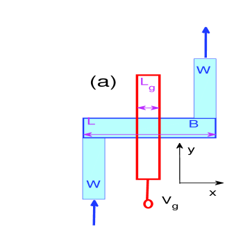
In the present paper we consider wave transmission through two types of the double-bend waveguides, namely - and -shaped quantum waveguides with a finger gate positioned across to the wire as shown in Fig. 1. Each bend of the waveguides has one transmission zero Weisshaar ; Shi ; Ming at some energy for the first channel transmission. Therefore the double-bend wire can be considered as a Fabry-Perot resonator (FPR) at the energy . The FPR can trap an electron if the distance between the bends is tuned to the integer number of half-wave lengths. Such a tuning is however hardly experimentally plausible. We propose to employ the finger gate potential in order to effectively tune the distance between the bends. We will show that multiple BSCs related to integer numbers of half wavelengths between the bends occur for positive potential. For a negative potential we will show the BSCs which are close to those considered by Robnik Robnik . Although in what follows we consider the electron transmission through the quantum double-bend waveguides the consideration is applicable to microwave transmission of TM waves owing to the equivalence between the Schrödinger equation and the Maxwell equations for planar electromagnetic waves. The dielectric slab inserted between the bents of a waveguide could play the role of the finger gate potential.
II Transmission through double-bend waveguides
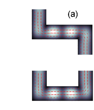
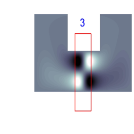
The standard technique to reduce the resonant widths in electron transmission through a quantum dot is to implement quantum point contacts. In the present paper we consider a different approach to selectively control the coupling between the inner states and the propagating states of the waveguides in the layouts shown in Fig. 1 (a) and (b). As shown in Fig. 1 we split each double-bend waveguide into three parts. The inner part outlined by bold blue line in Fig. 1 and denoted by ”B” plays the role of a bridge between two semi-infinite directional waveguides denoted by ”W”. The propagating states with the Fermi energy
| (1) |
in the waveguides are given by
| (2) |
where
| (3) |
Here the Fermi energy is measured in terms of , the coordinates are measured in terms of the width of waveguides and the wave vector is measured in terms of the inverse width of the waveguides. The eigenfunctions of the inner part ”B” are given by the following Schrödinger equation
| (4) |
| (5) |
| (6) |
and are the eigenfunctions and eigenenergies of a quantum particle in an infinitely deep box of width with the finger gate potential symmetrical in the -axis. The exact analytical expression for the potential profile was derived in Ref. Davies . If however the finger gate is close enough to the 2DEG, the potential can be well approximated by a rectangular step-wise function SadSher with height and width equal to the width of the gate.
The conductance of double-bent waveguides could be calculated with the use of the effective non-Hermitian Hamiltonian Sokolov ; Ingrid ; Stockmann ; Alhasid ; Pichugin ; SR
| (7) |
which is the result of projection of the total Hilbert space onto the inner space of the bridge using the Feshbach technique feshbach ; dittes . In this approach the waveguides are coupled to the bridge by the matrix whose elements are the coupling constants of the first channel propagating state (2) with the inner states (5) calculated via overlapping integrals of the form Pichugin ; SR ; Savin
| (8) |
Then the transmission amplitude is given by Sokolov ; Ingrid ; Stockmann ; Alhasid ; SR
| (9) |
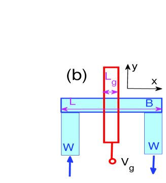
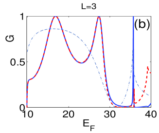
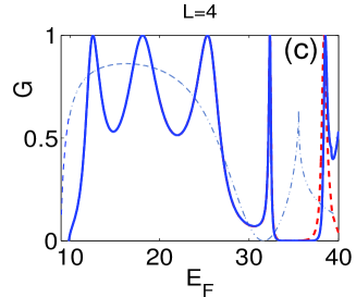
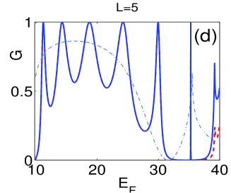
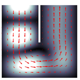
Computationally the method of the effective non-Hermitian Hamiltonian becomes efficient when adapted to a discretized form Datta ; SR equivalent to the finite-difference approach to the Schrödinger equation which is free from issues of poor convergence Pichugin . In Fig. 2 we plot the conductance in the Z-shaped waveguide in comparison to the conductance in the -shaped waveguide for for different lengths . First, one can observe resonant peaks which become narrower with the growth of . That observation was reported in Refs. Weisshaar ; Wu ; Wang ; Mekis however it did not receive a clear explanation. Second, below the threshold of the second channel but we see sharp asymmetric Fano resonances where the transmission can be either zero or unit depending on the type of the waveguide. For comparison we presented in Fig. 2 the conductance of the single bend waveguide by dash-dot line which does not exhibit resonances but has a transmission zero at energy . Third, the conductance in the Z-shaped waveguide differs from the conductance in the - shaped waveguide when the second channel of the bridge participates in the electron transmission. The difference between waveguides tends to zero with the extension of the length of the bridge. The transmission resonances for energies far below the second channel threshold are typical for the transmission through double barrier structure where peaks of the transmission correspond to standing waves between the barriers. Fig. 3 shows the scattering wave function which indeed demonstrate standing waves at the transmission resonances.
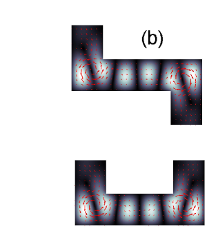
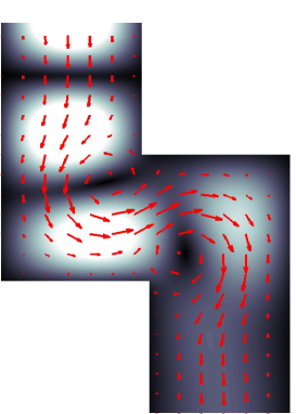
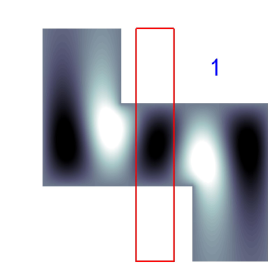
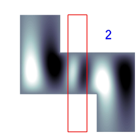
Figs. 3 (a) and 3 (b) show that mainly the eigenfunctions contribute to the scattering wave function for long waveguides with with the Fermi energy far from the second channel band edge. In the other words, the waveguides can be considered as one-dimensional in which there is no difference between the chirality sequence of the bends. The current flows demonstrate laminar regime respectively. When the energy is approaching the second channel edge the contribution of the second channel functions becomes relevant giving rise to vortical motion as it was first observed by Berggren and Ji Karl&Ji for electron transmission through a single bend waveguide. The direction of current circulation at the vortices depends on the chirality of the bend. Therefore the -shaped waveguide with the bends of the same chirality have vortices with the same clockwise or counter-clockwise current circulation while the -shaped waveguide with the bends of opposite chirality has vortices of opposite current circulation as seen from Figs. 3 (c) and 3 (d). As a result the current flows and respectively the transmission depends on the type of the double-bent waveguide. Fig. 4 shows that for the shortest bridge the current flow is vortical even for energies far from the second channel edge which gives rise to a difference in conductance for the whole energy band as seen from Fig. 2 (a). In Fig. 7 we show the first channel conductance for both types of waveguides versus the Fermi energy and the finger gate potential for a long bridge .
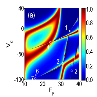
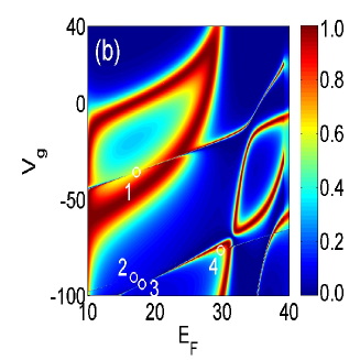
The waveguides show generally very similar conductance although with cardinally different pattern of the avoided crossings. As will be shown below that is reflected in the number and types of the BSC which denoted by open white circles in Fig. 7.
The resonant widths are controlled by the value of the coupling matrix elements (8). Because the longitudinal wave functions are normalized to have in the denominator we obtain that the resonant widths are inversely proportional to according to Eq. (7). That observation explains the tendency of narrowing of resonant peaks with the growth of the bridge length as shown in Fig. 2. Moreover, that opens an opportunity to control the resonant widths by the potential of the finger gate. This point has a key importance for the BSC and will be considered in the next section.
III Bound states in the continuum
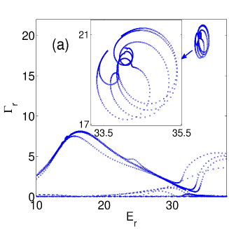
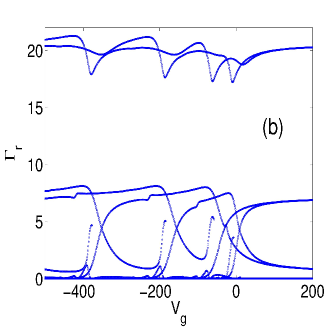
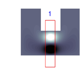
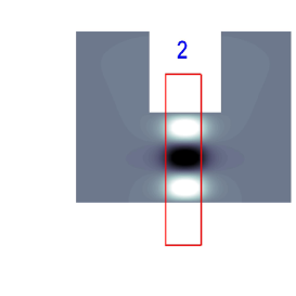
The complex eigenvalues of the effective Hamiltonian have a simple physical meaning Sokolov ; Ingrid ; Savin . Their real parts define the positions of the resonances with the resonance widths given by imaginary parts . In order to find the complex eigenvalues in case of noticeable radiation shifts it is necessary to solve the fix point equations for the resonance positions Ingrid . Resonant widths as functions of the finger gate potential show in Fig. 5 oscillating behavior because the longitudinal wave functions of the bridge tend to accumulate their nodal points on the waveguide-bridge interface as the probability distribution is pushed from the central region of the bridge with the growth of the finger gate potential as shown in Fig. 6 (a). As a result the overlapping integrals
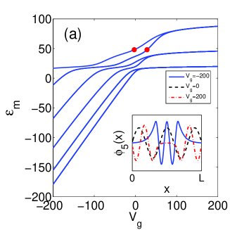
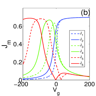
| (10) |
in the coupling matrix elements in Eq. (8) behave non monotonically as shown in Fig. 6 (b). Respectively one can see unusual behavior of the resonances shown in inset of Fig. 5 (a). As shown in Fig. 5 (b) further growth of gives rise to a hierarchical trapping of resonances predicted by Rotter and co-authors Iskra ; Muller as a result of the repulsion of complex eigenvalues of the effective Hamiltonian with the growth of the eigenvalue density. That phenomenon also takes place in -shaped waveguides at a different length .
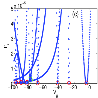
Next, under variation of the the finger gate potential a unique case can occur when the inverse of matrix in Eqs. (9) does not exist, when the determinant . That corresponds to and . These equations define the necessary and sufficient condition for the BSC ring ; PRA and can be combined into a single equation for the BSC point
| (11) |
The corresponding eigenfunction of the effective Hamiltonian is the BSC function, respectively. The solution Fig. 6 (c) demonstrates multiple BSCs denoted by red open circles occurring under variation of . An alternative approach to diagnose the BSC is calculating the poles of the S-matrix and finding the condition under which a complex pole tends to the real axis Pursey ; Ordonez ; Cattapan ; hatano ; Lee&Reichl ; Hein . Clearly, as the imaginary part of a pole or a complex eigenvalue tends to zero both methods yield identical results. The BSCs can be also be found in the conductance vs. the Fermi energy and the potential as the singular points where full reflection () meets the full transmission () PRB ; Lepetit ; Lepetit1 . These points are singular due to the collapse of the Fano resonances kim1 . In Fig. 7 (a) these points are marked by white circles and enumerated to show corresponding BSC functions in Fig. 8. The BSC function 3 is very similar to the BSC function 4 and is not shown in Fig. 8.
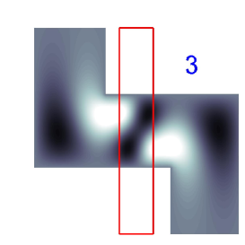
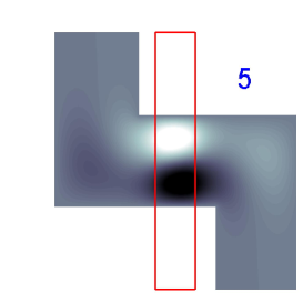
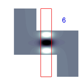
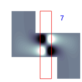
In Fig. 8 one can see two different types of BSCs. The first three 1-3 are due to the FPR mechanism discussed in the Introduction. The other three BSC functions 5-7 are reminiscent to those considered by Robnik Robnik in a directional quantum waveguide with a negative potential shown in Fig. 1 (c). In this case the Schrödinger equation is separable
| (12) |
which gives rise to the effectively one-dimensional transmission through a potential well
| (13) |
where
| (14) |
There are approximately one-dimensional bound states with discrete energies in the potential well with length in terms of the width of the waveguide and depth for Robnik . All bound states with and are below the first channel propagation band and therefore are not BSCs. But the bound states with and energies become BSC because of their orthogonality to the first channel propagation state with .
Turning back to the double-bent waveguides the symmetry arguments by Robnik are not valid because the coupling of some bridge state with the first channel can be cancelled only accidentally. The numerics show that it only occurs for the Fermi energy above the second channel threshold as shown in Fig. 7 (a). The reason is clear and can be readily seen from Eq. (8). For the coupling matrix element (8) to be equal to zero it is necessary that the wave function of the bridge had a nodal point at (see inset Fig. 6). That obviously corresponds to the second channel transmission as shown in Fig. 7 (a) by red closed circles. Therefore the BSC at are realized through the Friedrich-Wintgen interference mechanism. As Figs. 8 and Fig. 9 show the bridge wave function with longitudinal quantum number dominates in BSC functions 5 and 6. For the corresponding finger gate potentials given in the figure caption these function are mostly localized underneath the gate and decay exponentially in the waveguides. Therefore the contributions of the other bridge states to decouple the resonant state from the first propagation channel has to be also exponentially small as seen from Fig. 9 for BSCs 5 and 6.
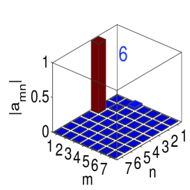
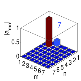
The BSC functions in the -shaped waveguide are shown in Fig. 10.
For and the chosen range of the finger gate potential the -shaped waveguide does not display the FPR type of the BSCs. Nevertheless the FPR type BSCs occur for . Finally in Fig. 11 we show the conductance of the shortest double-bend waveguides with the corresponding BSCs in Fig. 12 for the -shaped waveguide and Fig. 14 for the -shaped waveguide, respectively.
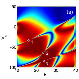
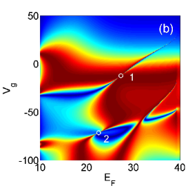
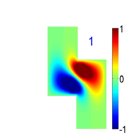
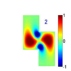
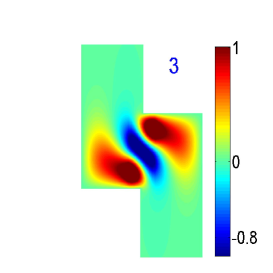
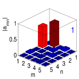
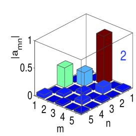
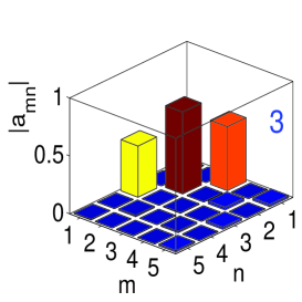
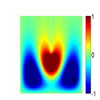
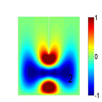
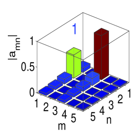
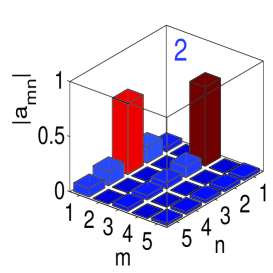
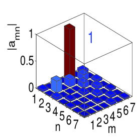
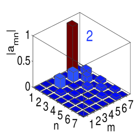
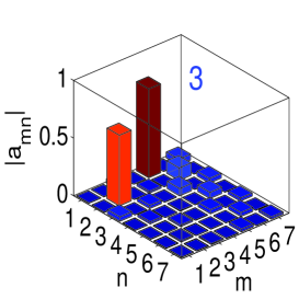
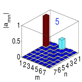
Fig. 13 shows the coefficients of the modal expansion of the BSCs in the waveguide with over the eigenfunctions of the bridge . One can see that only the first BSC can be approximately described by the Friedrich-Wintgen two-level approach. Similar expansions for the BSC in the -shaped waveguide shown in Fig. 15 demonstrate that the two-level approximation is applicable. Moreover one can see that only the eigenfunctions symmetrical in the -axis participate in the BSC which complies the symmetry of the waveguide.
IV Summary
We considered electron transmission in two types of double-bend waveguides, namely
- and -shaped waveguides. The waveguides differ in
the sequence of the chirality of the bends. In the -shaped waveguide the bends have the same chirality
with respect to the direction
of the flow, while in -shaped waveguide the bends have opposite chirality. It is demonstrated that because
of the difference in chirality
the vortices near the bends have different current circulation. That explains the difference
in conductance in those two types of waveguide. Alternatively, the origin of resonant peaks in the double-bend
waveguides is explained through the approach of the effective non-Hermitian Hamiltonian.
It is shown that although the central element (bridge)
in both types of waveguide is identical the difference in conductance arises from the structure of the coupling matrix (8) which
accounts for the coupling between the bridge and attached waveguides. Moreover the effective Hamiltonian approach
with the coupling matrix (8) explains narrowing of resonant peaks with enlarging of the bridge length .
The central result of the paper, however, is the electron localization between the bends thanks to bound states in the continuum (BSC)
with discrete energies embedded in the propagation band of the waveguide.
The BSCs like those in Figs. 8, 10, 12, and 14
are shown to be generic to both - and -shaped waveguides
subject to the static potential of a finger gate. Such double-bend waveguide
could be seen as a transistor with the finger gate voltage controlling the conductance as well as the
resonant widths. It is shown that the finger gate potential can tune the resonant widths
to zero as a result of variation of the coupling constants between the
eigenstates of the bridge and the first channel continuum.
Although it is hardly possible to visualize electron BSCs in microelectronics, they can be
registered as a singularities in the conductance
where the collapse of the Fano resonances occurs as shown in Figs. 7 and
11.
Such features were experimentally observed by
Lepetit et al Lepetit ; Lepetit1 for a dielectric resonator positioned in a
microwave waveguide. We speculate that employing the equivalence between quantum waveguides and
microwave systems with TM electromagnetic modes Stockmann
it could be possible to directly observe the BSCs in microwave double-bend waveguides.
Acknowledgments This work is supported by the Russian Science Foundation through Grant No.14-12-00266.
References
- (1) A. Weisshaar, J. Lary, S.M. Goodnick, and V. K. Tripathi, Appl. Phys. Lett. 55, 2114 (1989).
- (2) J.C. Wu, M.N. Wybourne, W. Yindeepol, A. Weisshaar, and S.M. Goodnick, Appl. Phys. Lett. 59, 102 (1991).
- (3) K. Vacek, A. Okiji, and H. Kasai, Phys. Rev. B47, 3695 (1993).
- (4) Chuan-Kui Wang, K.-F. Berggren, and Zhen-Li Ji, J. Appl. Phys. 77, 2564 (1995).
- (5) A. Mekis, J.C. Chen, I. Kurland, S. Fan, P.R. Villeneuve, and J.D. Joannopoulos, Phys. Rev. Lett. 77, 3787 (1996).
- (6) J.P. Carini, J.T.Londergan, D.P.Murdock, D. Trinkle, and C.S. Yung, Phys. Rev. B55, 9842 (1997).
- (7) Q.W. Shi, J. Zhou, and M.W. Wu, Appl. Phys. Lett. 86, 2547 (2004).
- (8) Yi Ming, Zhexian Wang, and Zejun Ding, Phys. Lett. A305, 302 (2006).
- (9) F. Sols and M. Macucci, Phys. Rev. B41, 11887 (1990).
- (10) Goodnick S. M.et al Quantum waveguide structures and devices //Physics and Computation, 1994. PhysComp’94, Proceedings., Workshop on. IEEE, 1994. . 169-176.
- (11) I. Kawamura and J.P. Lebarton, J. Appl. Phys. 73, 3577 (1993).
- (12) V.V. Sokolov and V.G. Zelevinsky, Nucl. Phys. A504, 562 (1989).
- (13) I. Rotter, Rep. Prog. Phys. 54, 635 (1991).
- (14) H.-J. Stöckmann, Quantum Chaos: An Introduction (Cambridge University Press, Cambridge,U.K.,1999).
- (15) Y. Alhassid, Rev. Mod. Phys. 72, 895 (2000).
- (16) K. Pichugin, H. Schanz, and P. Seba, Phys. Rev. E64, 056227 (2001).
- (17) A.F. Sadreev and I. Rotter, J. Phys. A 36, 11413 (2003).
- (18) J. von Neumann and E. Wigner, Phys. Z. 30, 465 (1929).
- (19) A.Z. Devdariani, V.N. Ostrovsky, and Yu.N. Sebyakin, Sov. Phys. JETP 44, 477 (1976).
- (20) H. Friedrich and D. Wintgen, Phys. Rev. A32, 3231 (1985).
- (21) A. Volya and V. Zelevinsky, Phys. Rev. C67, 054322 (2003).
- (22) A.F. Sadreev, E.N. Bulgakov, and I. Rotter, Phys. Rev. B 73, 235342 (2006).
- (23) S.P. Shipman and S. Venakides, Phys. Rev. E71, 026611 (2005).
- (24) D. C. Marinica, A. G. Borisov, and S.V. Shabanov, Phys. Rev. Lett. 100, 183902 (2008).
- (25) E.N. Bulgakov and A.F. Sadreev, Phys. Rev. B78, 075105 (2008).
- (26) T. Lepetit, E. Akmansoy, J.-P. Ganne, and J.-M. Lourtioz, Phys. Rev. B82, 195307 (2010).
- (27) T. Lepetit and B. Kanté, Phys. Rev. B90 241103 (2014).
- (28) Y. Plotnik, et al, Phys. Rev. Lett. 107, 183901 (2011).
- (29) G. Corrielli, G. Della Valle, A. Crespi, R. Osellame, and S. Longhi, Phys. Rev. Lett. 111, 220403 (2013).
- (30) S. Weimann, et al, Phys. Rev. Lett. 111, 240403 (2013).
- (31) Chia Wei Hsu, et al, Light: Science and Applications 2, 1 (2013).
- (32) Chia Wei Hsu, Bo Zhen, Jeongwon Lee, Song-Liang Chua, ,S.G. Johnson, J.D. Joannopoulos, and M. Soljačić, Nature, 499, 188 (2013).
- (33) M. Robnik, J. Phys. A: MAth Gen. 19, 3845 (1986).
- (34) J.H. Davies, I.A. Larkin, and E.V. Sukhorukov, J. Appl.Phys. 77, 4504 (1995).
- (35) A.F. Sadreev and E.Ya. Sherman, Phys. Rev. B88, 115302 (2013).
- (36) H. Feshbach H, Ann. Phys. (NY) 5, 357 (1958); ibid 19, 287 (1962).
- (37) F.M. Dittes, Phys. Rep. 339, 215 (2000).
- (38) D.V. Savin, V.V. Sokolov, and H.-J. Sommers, Phys. Rev. E67, 026215 (2003).
- (39) S. Datta, Electronic transport in mesoscopic systems, Cambridge University Press (1995).
- (40) K.-F. Berggren and Zhen-Li Ji, Phys.Rev. B47, 6390 (1993).
- (41) W. Iskra, I. Rotter, and F.-M. Dittes, Phys. Rev. C47, 1086 (1993).
- (42) M. Müller, F.-M. Dittes, W. Iskra, and I. Rotter, Phys. Rev. E52, 5961 (1995).
- (43) E.N. Bulgakov, K.N. Pichugin, A.F. Sadreev, and I. Rotter, JETP Lett. 84, 508 (2006).
- (44) E.N. Bulgakov, I. Rotter, and A.F. Sadreev, Phys. Rev. A75, 067401 (2007).
- (45) C.S. Kim, A.M. Satanin, Y. S. Joe, and R. M. Cosby, Phys. Rev. B 60, 10962 (1999).
- (46) D.L. Pursey and T.A. Weber, Phys. Rev. A52, 3932 (1995).
- (47) G. Ordonez, K. Na, and S. Kim, Phys. Rev.A73, 022113 (2006).
- (48) G. Cattapan and P. Lotti, Eur. Phys. J.B60, 51 (2007); ibid 66, 517 (2008).
- (49) H. Nakamura, N. Hatano, S. Garmon, and T. Petrosky, Phys. Rev. Lett. 99, 210404 (2007).
- (50) H. Lee and L.E. Reichl, Phys. Rev. B79, 193305 (2009).
- (51) S. Hein, W. Koch, and L. Nannen, J. Fluid Mech. 692, 257 (2012).