Magnetic detonation structure in crystals of molecular magnets
Abstract
Experimentally detected ultrafast spin-avalanches spreading in crystals of molecular (nano)magnets (Decelle et al., Phys. Rev. Lett. 102, 027203 (2009)), Ref. [Decelle-09, ], have been recently explained in terms of magnetic detonation (Modestov et al., Phys. Rev. Lett. 107, 207208 (2011)), Ref. [Modestov-det, ]. Here magnetic detonation structure is investigated by taking into account transport processes of the crystals such as thermal conduction and volume viscosity. In contrast to the previously suggested model, the transport processes result in smooth profiles of the most important thermodynamical crystal parameters – such as temperature, density and pressure – all over the magnetic detonation front including the leading shock, which is one of the key regions of magnetic detonation. In the case of zero volume viscosity, thermal conduction leads to an isothermal discontinuity instead of the shock, for which temperature is continuous while density and pressure experience jump.
I Introduction
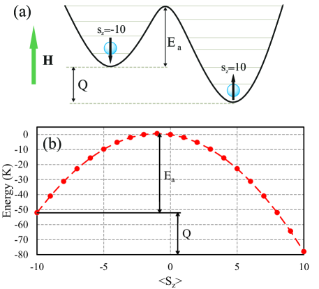
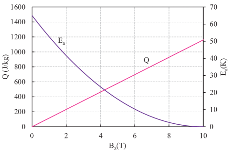
Presently there is much interest in molecular (nano) magnets with unique superparamagnetic properties, which may be used for quantum computing and memory storage. Bogani-Wernsdorfer-2008 ; Sarachik-2013 ; Suzuki-05 ; Hernandez-PRL-05 ; Subedi-2013 A remarkable feature of nanomagnets is that, in contrast to classical magnets, these macromolecules with large effective molecular spin (e.g., for Mn12-acetate) can keep their spin-orientation upon the reversal of the external magnetic field.mag:sessoli93 ; mag:villain94 Because of the strong molecular anisotropy, spin of a nanomagnet is directed preferentially along the so-called easy axis, and it leads to a considerable energy barrier between the spin-up and spin-down states. At low temperatures, in a magnetic field directed along the easy axis, the states with spin along the field and against the field become stable and metastable, respectively. The energy difference between the two states is determined by the Zeeman energy, , as illustrated in Fig. 1, with the energy barrier designated by . The barrier hinders spontaneous quantum tunneling from the metastable to stable state at low temperatures, mag:Friedman96 ; mag:thomas96 ; mag:chudnovsky98 ; mag:wernsdorfer01 ; mag:gatteschi03 so that fast spin-flipping requires help from outside.
For nanomagnets composing a crystal, relatively fast spin-flipping of one particular molecule may be induced by energy supplied by its’ neighbors. When all or most of the molecules of a crystal are initially in the metastable state, then local heating by an external source may trigger local spin-flipping, with Zeeman energy released in the heated region and transported to the next layer of the crystal.Sarachik-2013 ; Suzuki-05 ; Hernandez-PRL-05 ; Subedi-2013 ; Garanin-Chudnovsky-2007 ; Modestov-2011 ; McHugh-09 ; Dion-2013 ; Jukimenko-2014 The heat facilitates spin-flipping in the next layer, and so on, so that the process spreads in a crystal as a thin self-supporting magnetization front – spin-avalanche – well-localized spatially. Usually, energy in spin-avalanches is transported from one crystal layer to another by means of thermal conduction, and hence a spin-avalanche propagates at moderate speed, m/s.Sarachik-2013 ; Suzuki-05 ; Hernandez-PRL-05 ; Subedi-2013 Due to striking similarity of such avalanches to slow combustion flame, deflagration, avalanches of this type are typically called ”magnetic deflagration”.
In contrast to the slow magnetic deflagration studied in the absolute majority of works on the subject,Sarachik-2013 ; Suzuki-05 ; Hernandez-PRL-05 ; Subedi-2013 ; Garanin-Chudnovsky-2007 ; Modestov-2011 ; McHugh-09 ; Dion-2013 ; Jukimenko-2014 recent experiments of Ref. [Decelle-09, ] detected ultrafast spin-avalanches propagating at speed comparable to the sound speed in the crystals, m/s. The theory presented in Ref. [Modestov-det, ] has explained the ultrafast spin-avalanches in terms of ”magnetic detonation” and investigated the key properties of the process. In particular, it has been demonstrated that magnetic detonation belongs to the type of weak detonations and propagates with speed only slightly exceeding the sound speed m/s. Paper [Modestov-det, ] has also studied structure of magnetic detonation within the traditional combustion model of a detonation front consisting of an infinitely thin leading shock and a zone of energy release of finite thickness.Law-book Such a model has been originally developed for gaseous detonations, which are quite strong and propagate with speed exceeding the sound speed in gases by an order of magnitude. However, it is not rigorous applying such a model to magnetic detonation, which is extremely weak by combustion scales (although quite strong when compared to magnetic deflagration). In contrast to strong shocks in gases, which are infinitely thin from the hydrodynamic point of view, a weak shock exhibits a continuous structure controlled by transport processes such as thermal conduction and/or viscosity.LL_VI The same property should be naturally expected for magnetic detonation.
The purpose of the present work is to provide accurate description of magnetic detonation structure in crystals of nanomagnets by taking into account thermal conduction and volume viscosity. Here we show that, in contrast to the previously suggested model of Ref. [Modestov-det, ], the transport processes result in smooth profiles of the most important thermodynamical crystal parameters – such as temperature, density and pressure – all over the magnetic detonation front including the leading weak shock, which is one of the key regions of magnetic detonation. In the case of zero volume viscosity, however, thermal conduction leads to an isothermal discontinuity instead of the shock, for which temperature is continuous while density and pressure experience jump.
The present paper is organized as follows. In Sec. II we overview basic features of gaseous combustion detonation needed for proper understanding of magnetic detonation in crystals of nanomagnets. In Sec. III we present basic equations describing magnetic detonation, develop the analytical theory for the most important detonation parameters and study magnetic detonation structure controlled by thermal conduction only assuming zero volume viscosity – such a structure involves isothermal discontinuity instead of a shock employed in Ref. [Modestov-det, ]. In Sec. IV we demonstrate dramatic modifications of the magnetic detonation structure due to volume viscosity.
II Basic features of gaseous combustion detonation
In this section we remind briefly the most important features and the methods of investigation of traditional gaseous combustion detonations, in order to highlight the similarity and difference between the combustion and magnetic detonations. By definition, detonation is a fast supersonic combustion regime, for which preheating of the cold fuel mixture happens due to the leading shock, see Fig. 2. In turn, shock propagation without decay in combustion detonation is supported by energy release in chemical reactions in the active reaction zone. Typically for combustion, the activation energy of the reactions is quite high, so that reactions develop relatively slow just after the leading shock in the so-called induction zone (still, much faster than in the fuel mixture). It requires certain (induction) time for self-acceleration of chemical reactions in a gas parcel after passing the shock, after which the chemical reactions become fast and convert the fuel mixture into the burning products with release of a large amount of energy and strong expansion of the burning gas.
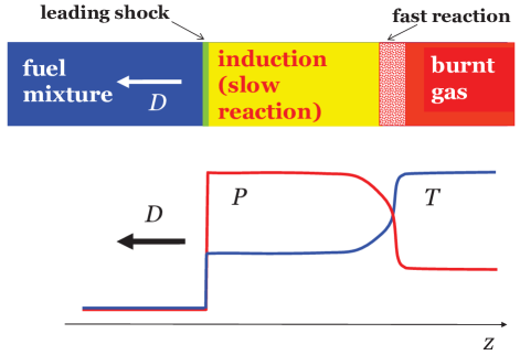
Here we are interested in a planar stationary one-dimensional detonation propagating with constant supersonic speed in a uniform gaseous mixture; we take the detonation front propagating along the z-axis in the negative direction. By adopting the reference frame of the stationary detonation front, we obtain the fuel mixture moving with velocity towards the leading shock of zero thickness; the initial density, pressure and temperature are designated by , and . The fuel mixture is compressed in the shock (label ””) with strong increase of density, pressure and temperature to , , , and with drop of the gas velocity to a new subsonic value . Temperature increase initiates combustion reactions with release of chemical energy, hence leading to even stronger temperature increase until it reaches the final maximal value in the detonation products (label ””), . At the same time, pressure and density decrease in the reaction region, , , as illustrated schematically on Fig. 2.
Modifications of the gas parameters in a detonation front are described by the hydrodynamic laws of mass, momentum and energy conservation expressed in terms of fluxesLL_VI
| (1) |
| (2) |
| (3) |
where is the gas enthalpy
| (4) |
is the adiabatic exponent, is the chemical energy stored per unit mass, is fraction of the unburned fuel mixture, which changes from in the fresh and shocked gas to in the detonation products. The hydrodynamic equations Eqs. (1)-(3) are complemented by the equation of state, which is taken for gaseous detonations in the form of the ideal gas law
| (5) |
where is the ideal gas constant and is the molar mass of the gas (for simplicity we assume here that the molar mass does not change in the combustion process). Traditionally, the theory of shock waves and detonations employs volume per unit mass for analyzing the process.LL_VI
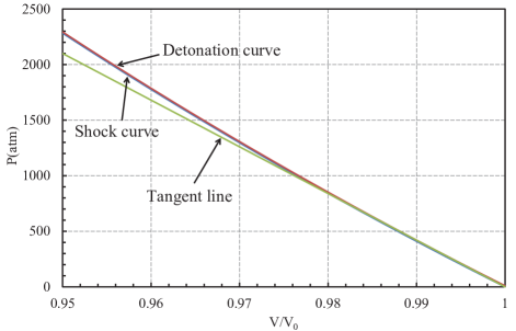
Modifications of the gas parameters in a leading shock are described by Eqs. (1)-(3) with zero energy release in the reaction within the discontinuous shock, . Then Eqs. (1)-(3) may be reduced to the so-called Hugoniot equation, which specifies all possible finite states of the shocked gas for a fixed initial state ; the result is demonstrated by the blue solid curve in Fig. 3 for the initial state corresponding to the ideal gas at initial volume per unit mass and pressure Pa. For any particular final state at the shock, equations (1), (2) relate the slope of the green straight line () in Fig. 3 to the front propagation speed asLL_VI
| (6) |
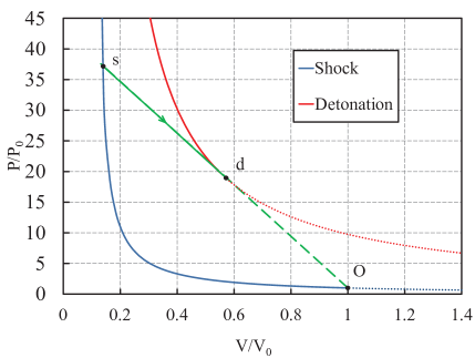
In order to obtain the final state of the detonation products we solve Eqs. (1)-(3) for the case of complete burning ; the result is plotted by the solid red curve in Fig. 3 for the scaled energy release corresponding to the acetylene-air combustion.Ott-2003 The red curve (for detonation) corresponds to higher pressure for the same volume than the blue curve (for a shock) due to the energy release in a detonation front. Still, unlike a shock, detonation speed is not a free parameter, but it is determined by particular boundary conditions. For example, the case of a freely propagating detonation corresponds to the so-called Chapman-Jouguet (CJ) detonation regime, with the detonation products moving away from the front at local sound speed.LL_VI The CJ detonation propagates with the smallest speed possible for detonations for a fixed energy release, and indicated by the green tangent line in Fig. 3. Thus, on the pressure-volume diagram, the CJ detonation structure corresponds first to the jump from the point (the initial state) to the point at the shock, and then the reaction development behind the shock along the green straight line from the point to the point (detonation products). It may be shown that the CJ detonation speed is determined by the energy release in the combustion process.LL_VI
The internal structure of the reaction zone in the detonation front (transition from the point to the point in Fig. 3) is specified by reaction kinetics of a particular fuel mixture. Here we illustrate the detonation structure for the simplified model of acetylene-air combustion described by a single one-step Arrhenius reactionOtt-2003
| (7) |
where is a pre-exponential factor, is the scaled activation energy. Then the stationary detonation structure is determined by Eq. (7) rewritten in the reference frame of the front as
| (8) |
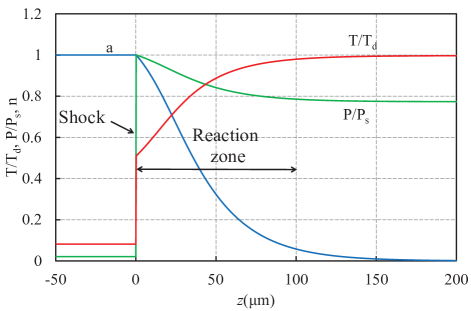
By solving Eq. (8) together with Eqs. (1)-(3) we find the detonation front structure as shown in Fig. 4. For obtaining the plots we have used the scaled energy release , with the initial gas pressure and temperature . Then by using the conservation laws Eqs. (1)-(3) one can find the maximal pressure in the detonation front achieved at the shock as and maximal temperature achieved in the detonation products ; these two values have been used for scaling in Fig. 4. As we can see, Fig. 4 presents the detonation structure similar to the qualitative sketch of Fig. 2, although the induction length is exhibited not so strongly by the acetylene-air detonations.
III Magnetic detonation structure due to heat transfer
III.1 Basic equations
The theory of combustion detonation summarized briefly in the previous section provides the clue for describing the magnetic detonation in crystals of nanomagnets; conceptually the same model has been employed for the analysis of magnetic detonation in Ref. [Modestov-det, ]. Still, here we stress important difference in some combustion and magnetic detonation properties, which is taken into account below. First, magnetic detonation in crystals of nanomagnets is extremely weak, so that it propagates with speed only slightly exceeding the sound speed in the crystal, . For that reason, in stark contrast to combustion detonations, the leading shock in magnetic detonation is not a discontinuity, but a smooth transition region with structure determined by transport processes, namely, thermal conduction and volume viscosity , which requires proper modifications of the conservation laws Eqs. (1)-(3) at the detonation front.
So far the theoretical models of spin-avalanches in crystals of nanomagnets have taken into account only thermal conduction and neglected volume viscosity;Garanin-Chudnovsky-2007 ; Modestov-2011 ; McHugh-09 ; Dion-2013 in the present section we use the same approach and consider the influence of thermal conduction only. Volume viscosity will be taken into account in the next section. Although we deal with solid state, propagation of shocks and detonations in crystals of nanomagnets is also described by the hydrodynamic conservation laws of mass, momentum and energy similar to Eqs. (1)-(3), see Refs. [Zeldovich-02, ; Modestov-det, ]
| (9) |
| (10) |
| (11) |
where is the thermal energy per molecule, stands for Zeeman energy and is the fraction of molecules in the metastable state. Zeeman energy , together with the activation energy , are determined by the applied magnetic field, and can be obtained by using Hamiltonian for Mn12-acetate molecule mag:delbarco05
| (12) |
where is the magnetic field, is the gyromagnetic factor, is the Bohr magneton, and is the magnetic anisotropy constant. We assume that the field is applied along the easy axis (z-axis). Zeeman energy is found as the energy difference between the stable, , and metastable, , states of the nanomagnet as illustrated in Fig. 1
| (13) |
Zeeman energy increases linearly with the magnetic field. Activation energy is determined by the energy barrier between stable and metastable states, see Fig. 1, and for nanomagnets it may be found as
| (14) |
the activation energy is provided in temperature units. Dependence of Zeeman and activation energies on the applied magnetic field is presented in Fig. 5 for Mn12-acetate. As we can see, the activation energy decreases with the magnetic field and turns to zero at ; at higher fields the potential barrier disappears and the transition from the state to the state is not hindered any more.
It is convenient to define new dimensionless value , which represents possible compression of the crystal in the process of magnetic detonation. Weak shock and detonation cause only elastic deformations, and the equation of state for the crystals of nanomagnets may be written as a combination of elastic and thermal components asZeldovich-02 ; Modestov-det
| (15) |
where is the molecular mass with g/mol for Mn12-acetate, see Ref. [Sarachik-2013, ]. Similar to Ref. [Modestov-det, ] we take , the Gruneisen coefficient , the problem dimension , and the Debye temperature K. The coefficient corresponds to the Debye crystal lattice, and is sound speed in the crystal. Thermodynamic energy per one molecule of the crystal is given byZeldovich-02 ; Modestov-det
| (16) |
Equations (9)-(III.1) provide a complete system for describing magnetic detonation parameters in crystals of nanomagnets with thermal conduction taken into account.
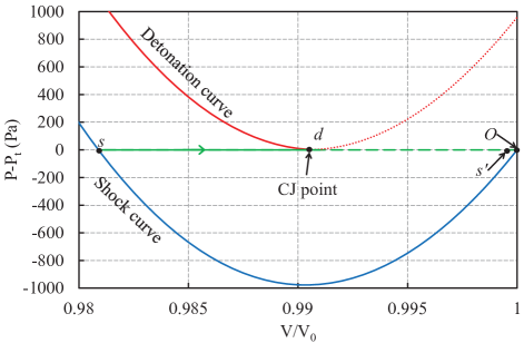
Solution to Eqs. (9)-(III.1) is presented in Fig. 6 in terms of the pressure-volume diagram for the magnetic detonation structure similar to Fig. 3. We can see immediately that, since magnetic detonation is extremely weak, the shock curve (blue) and the detonation curve (red) almost coincide; similar to Fig. 3, the tangent line from the initial state to the CJ detonation regime is shown by green. In the case of zero viscosity, pressure at the tangent line (label ””) follows from Eqs. (9), (10) as
| (17) |
In order to make difference between the shock and detonation visible, we modify the pressure-volume diagram by extracting pressure at the tangent line, Eq. (17), i.e. plotting versus , see Fig. 7. Within such a representation, the tangent line (by definition) becomes simply the zero-line, while the shock and the detonation states may be well-distinguished and represented by two curves resembling parabola pieces.
III.2 The analytical theory for the key magnetic detonation parameters
As we can see in Fig. 7, the limit of weak compression holds with a very good accuracy for magnetic detonations, and hence allows developing the analytical theory of the process. The system Eqs. (9)-(III.1) may be reduced to a single equation, which is equivalent to the Hugoniot relationLL_VI with thermal conduction taken into account
| (18) |
By combining the equations of state for the crystals of nanomagnets, Eqs. (15), (16), we get rid of the thermal terms and obtain the expression for thermodynamic energy as function of and only
| (19) |
Then substituting Eq. (III.2) into the Hugonoit relation Eq. (18) we obtain pressure as
| (20) |
In a similar way, by substituting Eqs. (15), (16) into Eq. (18) we find temperature
| (21) |
Now we take into account that density variations in the magnetic detonation are small by introducing a small value . We can also neglect initial thermodynamic energy since . First, we analyze the detonation products, , for which the transformation process is completed, . Expanding Eq. (III.2) in powers of and taking we obtain pressure in the detonation products as
| (22) |
The scaled density deviation corresponding to the CJ point of the detonation products on Fig. 7 is unknown so far and we have to find it. At the CJ point the tangent line touches the detonation curve, which implies
| (23) |
| (24) |
For small compression case we rewrite Eq. (17) as
| (25) |
Substituting Eqs.(III.2) and (25) into Eq.(23), (24), we find
| (26) |
| (27) |
Then, eliminating from Eqs. (III.2), (III.2), and keeping terms as small as we obtain
| (28) | ||||
We may also use the condition justified below to simplify Eq. (III.2) and find the density deviations in the detonation products as
| (29) |
As an example, for the external magnetic field of we obtain the density deviations from the initial value as small as . Temperature of the detonation products may be calculated with the accuracy of the first order terms in as
| (30) |
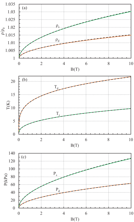
Figure 8 shows density, temperature and pressure of the detonation products versus the applied magnetic field as found in the numerical solution and predicted by the analytical formulas Eq. (III.2), (29), (III.2); we observe excellent agreement of the theory with the numerical solution. We also point out that the magnetic detonation speed may be obtained from Eq. (III.2) up to the leading terms in as:
| (31) |
Keeping the leading terms we can rewrite Eq.(III.2) as:
| (32) |
Substituting Eq. (29) in Eq. (32) and taking into account we find the magnetic detonation speed
| (33) |
Thus, in agreement with Ref. [Modestov-det, ], the magnetic detonation speed only slightly exceeds the sound speed in the crystals.
It is also useful finding thermodynamic parameters of the crystal just behind the shock, , neglecting thermal conduction, i.e. treating the shock as a discontinuity similar to Ref. [Modestov-det, ]. We will show in the next subsection, that the same values for temperature, pressure and density hold at the isothermal discontinuity taking into account thermal conduction. So, we are looking for the density deviations corresponding to the crystal just behind an infinitely thin shock. Equation (III.2) yields up to the second order terms in
| (34) |
The tangent line intersects the shock curve at the point , which implies or
| (35) |
Taking into account the result for the magnetic detonation speed, Eq. (III.2), we obtain the equation for
| (36) |
which may be solved with the accuracy of as
| (37) |
It is noted that density deviation just behind the discontinuous shock is about twice larger than in the detonation products, which may be seen already in Fig. 7. Then we find temperature on the shock similar to Eq. (III.2)
| (38) |
Density, temperature and pressure at the leading shock in magnetic detonation are shown in Fig. 8; we again observe a very good agreement of the analytical theory and the numerical solution.
III.3 Isothermal discontinuity in magnetic detonation
In this subsection we obtain the magnetic detonation structure in presence of thermal conduction. By using Eqs. (15), (17) we find temperature as a function of scaled density inside the magnetic detonation front
| (39) |
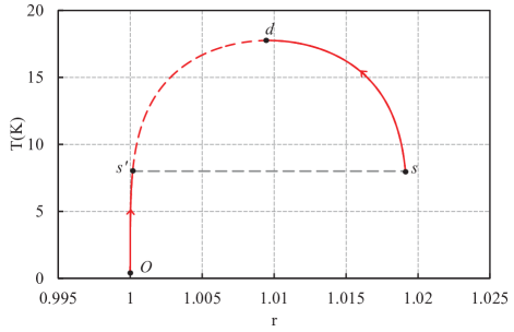
By plotting temperature according to Eq. (39) from the initial point to the shock point , we observe non-monotonic temperature variations, see Fig. 9, with the maximum value attained at the detonation point . In that case, assuming hypothetic temperature variations along the red curve (solid and dashed) in Fig. 9 from to in the whole detonation front, one moves first from to , then passes to the shock point , and then returns back from to the final state . Along such a pass we obtain the region with temperature decrease on the way from to the shock point . However, the left hand-side of Eq. (18) turns to only at the boundaries of the detonation wave , i.e. it has to be either positive or negative in the transition zone from to , see Refs. [Zeldovich-02, ; LL_VI, ]. Since detonation definitely leads to temperature increase as compared to the initial state, then we have the condition satisfied everywhere in the magnetic detonation front, so that the hypothetic region with is not physical and should be avoided. Then, variations of all values in magnetic detonation in Fig. 9 have to correspond to continuous movement from the initial point to the point , which is followed by jump to the shock point with subsequent continuous evolution to the final detonation point . At the same time, because of thermal conduction in Eqs. (9) - (III.1), temperature has to be continuous in magnetic detonation including the shock wave. For that reason, instead of a traditional shock, we obtain isothermal discontinuity in magnetic detonation in the case of negligible volume viscosity when the shock structure is supported by thermal conduction only. An important point is that compression of the crystal in the point is quite small, , so that the isothermal discontinuity resembles a shock for density and pressure. The visual difference is found only for temperature variations.
The internal structure of magnetic detonation can be obtained by integrating the equation for kinetics of spin-relaxation,Garanin-Chudnovsky-2007 which resembles strongly the Arrhenius law of chemical kinetics Eq. (7),
| (40) |
By adopting the reference frame of the stationary magnetic detonation front, Eq. (40) can be written as
| (41) |
By using Eq. (39), we solve Eq.(41) numerically starting from the initial point to the point of isothermal discontinuity . After that new values for density and pressure at the point are calculated according to the jump conditions, with temperature and fraction of metastable molecules kept constant. Then numerical calculation is performed from the point to the final detonation state . The result of the numerical solution is presented in Fig. 10 for the Mn12-acetate crystals with the characteristic thickness of the detonation front employed as the length scale.
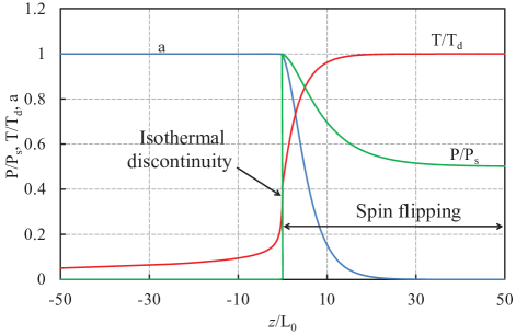
In Fig. 10 for illustrative purposes we plot the numerical solution for the thermal conduction coefficient , which is about five times larger than the commonly accepted value , e.g. see Refs. [Garanin-Chudnovsky-2007, ; Dion-2013, ]. Still, even in that case thickness of the heating region is much smaller than the region of spin-flipping, and fraction of the molecules in the metastable state is close to unity at the isothermal discontinuity, .
Thus, as an intermediate conclusion, thermal conduction influences only the temperature profile in magnetic detonation, with a minor effect on density and pressure, and with negligible modifications of the total front thickness. Much more dramatic modifications of the magnetic detonation structure are expected because of volume viscosity as shown in the next section.
IV Detonation front with viscosity
By taking into account volume viscosity, , we re-write the equations of mass, momentum and energy conservation for magnetic detonation as
| (42) |
| (43) |
| (44) |
We point out that, unlike commonly known shear viscosity arising due to relative motion of gas or fluid layers, volume viscosity describes momentum and energy dissipations due to compression of a medium. While shear viscosity is not typical for solid state processes such as magnetic detonation in crystals of nanomagnets, volume viscosity has to be considered. It is convenient characterizing the role of viscosity by the dimensionless parameter
| (45) |
This dimensionless viscosity plays a role conceptually similar to that of the inverse Reynolds number in fluid mechanics.LL_VI In particular, the parameter values employed below correspond to the domain of the Reynolds numbers . At such values of the Reynolds number gas and fluid flows are typically laminar; negligible role of viscosity is qualitatively indicated by transition to turbulence, which happens usually at larger values, and above. To the best of our knowledge, there have been no works, either experimental or theoretical, investigating volume viscosity in crystals of nanomagnets, and therefore we will take as a free parameter.
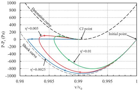
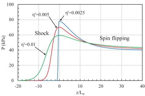
We stress that even small values of volume viscosity lead to considerable changes in the magnetic detonation structure as shown in Figs. 11 - 14. Even on the pressure-volume diagram, Fig. 11, (plotted, as before, for by extracting the CJ-tangent line for illustrative purposes) we observe that all discontinuous jumps of the previous modelModestov-det are replaced by continuous transition lines from the initial point to the CJ detonation products. For very small viscosity, , the transition line (blue), although continuous, goes pretty close to the Hugoniot curve for the shock and then to the tangent line for the spin-flipping process. In a similar way, in Fig. 13 the plot for demonstrates quite abrupt initial pressure increase – almost jump, which resembles strongly a discontinuous shock wave; this pressure increase is followed by pressure relaxation to a smaller value in the process of spin-flipping with Zeeman energy release. As we take larger values of volume viscosity, , deviation of the pressure-volume plots from the discontinuous shock model becomes much more pronounced, Fig. 11, and we find pressure and density in the shock wave decreasing as compared to the discontinuous case, Fig. 13. In fact, the very definition of a shock as a part of magnetic detonation front becomes ambiguous when volume viscosity is taken into account. To avoid the ambiguity, we notice that within the model of a discontinuous shock, pressure maximum is attained at the shock front, and then pressure goes down as the spin-flipping starts. In the same way it seems natural treating the point of maximal pressure in Figs. 12, 13 as the back-side of the shock region. In Fig. 13 we placed all three plots by choosing as the position of the pressure maximum and hence the back side of the shocks. Then the regions corresponding to belong to the shocks smoothed by viscosity, while the domain of may be treated roughly as the regions of spin-flipping with Zeeman energy release.
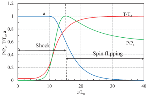
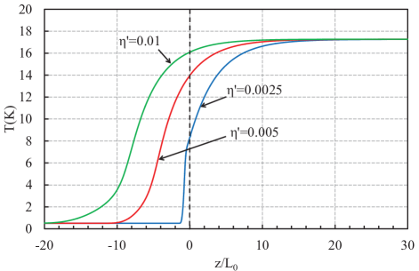
Of course, such separation is rather qualitative than quantitative, because in presence of considerable volume viscosity spin-flipping starts already in the shock, see Fig. 12 corresponding to , . In Fig. 12 the fraction of nanomagnets in the metastable state is about at the point of pressure maximum. Figure 14 compares temperature profiles for the scaled viscosity with the respective pressure maxima still placed at . As we can see, larger volume viscosity increases strongly temperature at the shock; in the case of temperature at is only 5% smaller than the final detonation temperature, i.e. it is about . Temperature increase reduces strongly the size of the ”pure” spin-flipping region, still, as we can see from Fig. 14, it is accompanied by strong increase of the width of the shock wave, so that total width of magnetic detonation front does not change much, being about for all three cases, i.e. about mm in dimensional units.
We point out that the experimentally employed sample sizes for the crystals of nanomagnets are also about 2 mm, e.g. see Refs. [Decelle-09, ; Subedi-2013, ]. As a result, it is rather difficult to observe steady well-developed magnetic detonation in the commonly experimental conditions. Instead, we suggest that most of the experimental points reported in Ref. [Decelle-09, ] for ultra-fast magnetic avalanches correspond to magnetic detonation in the process of development, which is also indicated by the average avalanche speed in the samples noticeably below the sound speed. Another important feature of the experimental observations of Ref. [Decelle-09, ] is that the ultra-fast avalanches were obtained for the magnetic field close to the quantum resonance values of the nanomagnets. Quantum resonances lead to strong decrease of the factor in the kinetic equation of spin-flipping, Eq. (40), and hence of the characteristic width of the magnetic detonation front , which may allow experimental observation of magnetic detonation in samples of conventionally employed sizes.
V Summary
In the present paper we have investigated the internal structure of magnetic detonation in crystals of nanomagnets. Magnetic detonation is weak and propagates with speed only slightly exceeding the sound speed in the crystals. For that reason, in stark contrast to usual combustion detonations, transport processes – thermal conduction and volume viscosity – play an important role in forming the magnetic detonation structure. We show that, in the case of negligible volume viscosity, thermal conduction produces isothermal discontinuity instead of the leading shock in magnetic detonation. In the isothermal discontinuity temperature of the crystal is continuous, while density and pressure experience jump.
Volume viscosity leads to much more dramatic changes of the magnetic detonation structure as compared to the model of Ref. [Modestov-det, ] with neglected transport processes. In that case all important thermodynamic parameters of the crystals acquire smooth profiles all over the magnetic detonation front including the leading shock. In addition, the very concept of the leading shock requires unambiguous definition – here we suggest to specify the back side of the shock as the position of the pressure maximum. As the relative role of volume viscosity increases, the leading shock becomes wider and may exceed considerably the zone of spin-flipping by size. Still, total size of a magnetic detonation front does not change much with variations of volume viscosity since decrease of the spin-flipping region is compensated by increase of the shock width.
Acknowledgements
This work has been supported by the Swedish Research Council (VR).
References
- (1) W. Decelle, J. Vanacken, V. V. Moshchalkov, J. Tejada, J. M. Hernández, and F. Macià, Phys. Rev. Lett. 102, 027203 (2009).
- (2) M. Modestov, V. Bychkov, and M. Marklund, Phys. Rev. Lett. 107, 207208 (2011).
- (3) L. Bogani, W. Wernsdorfer, Nature Mater. 7, 179 (2008).
- (4) Myriam P. Sarachik, Magnetic avalanches in molecular magnets, 2013, arXiv:1302.5100.
- (5) Y. Suzuki, M. P. Sarachik, E. M. Chudnovsky, S. McHugh, R. Gonzalez-Rubio, N. Avraham, Y. Myasoedov, E. Zeldov, H. Shtrikman, N. E. Chakov, and G. Christou, Phys. Rev. Lett. 95, 147201 (2005).
- (6) A. Hernández-Mínguez, J. M. Hernandez, F. Macià, A. García-Santiago, J. Tejada, and P. V. Santos, Phys. Rev. Lett. 95, 217205 (2005).
- (7) P. Subedi, S. Vélez, F. Macià, S. Li, M. P. Sarachik, J. Tejada, S. Mukherjee, G. Christou, and A. D. Kent, Phys. Rev. Lett. 110, 207203 (2013).
- (8) R. Sessoli, D. Gatteschi, A. Caneschi, and M. A. Novak, Nature 365, 141 (1993).
- (9) J. Villain, F. Hartman-Boutron, R. Sessoli, and A. Rettori, Europhys. Lett. 27, 159 (1994).
- (10) J. R. Friedman, M. P. Sarachik, J. Tejada and R. Ziolo, Phys. Rev. Lett. 76, 3830 (1996).
- (11) L. Thomas, F. Lionti, R. Ballou, D. Gatteschi, R. Sessoli, and B. Barbara, Nature 383, 145 (1996).
- (12) E. M. Chudnovsky and J. Tejada, Macroscopic Quantum Tunneling of the Magnetic Moment (Cambridge University Press, Cambridge, 1998).
- (13) W. Wernsdorfer, Adv. Chem. Phys. 118, 99 (2001).
- (14) D. Gatteschi and R. Sessoli, Angew. Chem. Int. Ed. 42, 268 (2003).
- (15) D. A. Garanin and E. M. Chudnovsky, Phys. Rev. B. 76, 054410 (2007).
- (16) M. Modestov, V. Bychkov, and M. Marklund, Phys. Rev. B 83 214417 (2011).
- (17) S. McHugh, B. Wen, X. Ma, M. P. Sarachik, Y. Myasoedov, E. Zeldov, R. Bagai, and G. Christou, Phys. Rev. B 79, 174413 (2009).
- (18) C. M. Dion, O. Jukimenko, M. Modestov, M. Marklund, and V. Bychkov, Phys. Rev. B 87 014409 (2013).
- (19) O. Jukimenko, C. Dion, M. Marklund, and V. Bychkov, Phys. Rev. Lett 113 217206 (2014).
- (20) C. K. Law, Combustion Physics (Cambridge University Press, Cambridge, 2006).
- (21) L. Landau, E. lifshitz, Fluid Mechanics, Pergamon Press, Oxford (1989).
- (22) James D.Ott, Elaine S. Oran and Jhon D. Anderson Jr., AIAA Journal, 41, 1391 (2003).
- (23) Ya. B. Zeldovich and Yu. P. Raizer, Physics of shock waves and high-temperature hydrodynamic phenomena (Dover Publications, Inc., Mineola, NY, 2002).
- (24) E. del Barco, A. D. Kent, S. Hill, J. M. North, N. S. Dalal, E. M. Rumberger, D. N. Hendrickson, N. Chakov, and G. Christou, J. Low Temp. Phys. 140, 119 (2005).