Massive MIMO testbed - Implementation and Initial Results in System Model Validation
Abstract
This paper presents the design and implementation of a novel SDR based massive MIMO testbed with up to 70 nodes built at Tennessee Technological University. The deployment can reach a antenna MIMO scheme. With this testbed, we are able to measure the channel matrix and compute the achievable rate of the massive MIMO system using experimental data. The measured channel capacity is linearly increasing with the number of antennas of the base station. We also demonstrate the channel reciprocity including the circuits impact from the transmitter and receiver. We show that the Vandermonde channel model is more realistic to describe the massive MIMO architecture than the widely used Gaussian channel model, in terms of capacity. By adjusting the range for angle of arrival and the base station antenna distance during the simulation, we find out the Vandermonde model agrees with our measured capacity at a certain for each selected and the is very close to that of the experiment deployment. It is the first time that the feasibility of Vandermonde channel model is demonstrated by the experiment for massive MIMO.
Index Terms:
Massive MIMO, Software Defined Radio, testbed, Channel ModelI introduction
Massive MIMO, as an candidate for one of the disruptive technologies of the next generation (5G) communications system, promises significant gains in wireless data rates and link reliability [1] [2]. By using large numbers of antennas at the base station, massive MIMO helps to focus the radiated energy toward the intended direction while minimizing the intra and intercell interference.
While promising, the research challenges of massive MIMO also emerge with the dramatically increased number of antennas at the base station. Obtaining channel state information is an essential operation for communications but the pilot contamination could occur due to the limited pilots for massive MIMO.
Most of the current theoretical analysis on large MIMO assume a Gaussian Channel matrix [3] [4]. However, Gaussian channel could be not accurate in real environment. The channel could be correlated due to spatial impact. Specially, in the sectorized celluar network outdoors, signals from the mobile users in a sector could be distributed within a narrow angle ]. The Vandermonde matrix can be used to depict the channel model of the outdoor LOS propagation path for the large antennas system [5] [6] [7]. Most of the current research on massive-MIMO is limited to theory based on the analytical and simulation results, and lacks of the experimental support. Thus our experimental research is motivated to verify the theoretical results and to find the effect of massive MIMO in real propagation environment. We built a prototype of massive MIMO of testbed with the commercial SDR platfrom - USRP N210. With high performance computer and SDR nodes, we developed a massive MIMO experiment testbed supporting up to scheme. We also developed the software to support the distributed data collection and computing architecture. Our preliminary experimental work based on this testbed include
-
•
Implement of the TDMA protocol to ensure the orthogonality in channel measurement;
-
•
Compute the massive MIMO capacity based on the measured channel matrix, pre-coding is also considered;
Our experimental results show the linearity of the capacity with the increasing number of antennas by assuming it is the same with the number of mobile users. Further, more importantly, we found out that our measured capacity agrees with the simulated capacity under Vandermonde channel model. It is the first time that the feasibility of Vandermonde channel model is demonstrated by experimental result.
tntech
II Theoretical Model
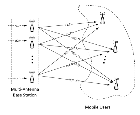
Considering a point-to-point MIMO system in which there are transmit antennas and receive antennas. For the narrow band channel, assuming the transmitters transmit the data simultaneously, the mathematical description of the signal model is as below:
| (1) |
where is the transmitted vector satisfying the , is the common SNR(signal-to-noise-ratio) at each receive antenna and is a vector of complex Guassian noise complying to zero mean and unit-variance i.i.d(independent and identical distribution), is the channel response matrix.
II-A Capacity and achievable rates
Under the assumption that the receiver has perfect knowledge of channel matrix , the capacity of the MIMO channel is computed by
| (2) |
where is the identity matrix and the means hermitian transposition.
II-B Vandermonde Channel Model
In [5] [6] [7] the Vandermonde random matrix
| (3) |
is introduced to describe the channel model for a base station receiver with antennas and mobiles, where is the antenna spacing and is the wavelength. As in fig. 1, the angles of arrival are supposed to be uniformed distributed within . The elements of the Vandermonde matrix can also have phases with uniform distribution for comparison. The received signal at the base station is given by
| (4) |
where , , are respectively the received vector, the transmit vector, and the additive noise, is the Vandermonde channel matrix, is the power gain matrix which can be set as identity matrix in simulation.
The Vandermonde model, compared with Gaussian channel model, is close to the real massive MIMO system from the architecture point of view.
III System design and experiment setup
III-A Channel Measurement
The channel matrix is key to compute the MIMO system capacity. Denote as the frequency response for the link between the transmit antenna and receive antenna . Assuming the narrowband channel, the channel can be measured by the PN sequence correlation [8].
At the transmitter, a PN sequence with length of 512, , is transmitted. The auto-correlation function of the PN sequence is
| (5) |
At the receiver, the correlation between the received sequence, and the known transmitted PN sequence, is
| (6) |
Thus the is computed based on eq. 6.
In the real channel measurement, the TDD(Time division duplex) is introduced to measure the channel matrix by ensuring the orthogonality of the channel sounding signal.
III-B Experiment Deployment and System Architecture
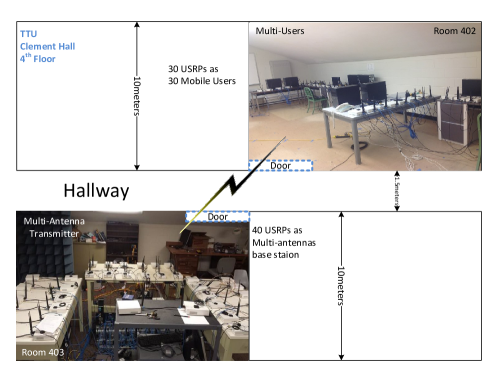
In the wireless networking systems lab (WNSL) of Tennessee Tech university (TTU), we built a massive MIMO testbed based the general SDR platform - USRP. Seventy USRPs controlled by thirty high performance PCs are deployed on the 4th floor of Clement Hall on the campus of TTU. As shown in Fig. 2, two groups of USRPs are placed in two separate rooms. Forty USRPs are deployed in the WNSL to emulate multi-antenna base station, while the rest of the USRPs are randomly arranged in another room acting as mobile users with single antenna.
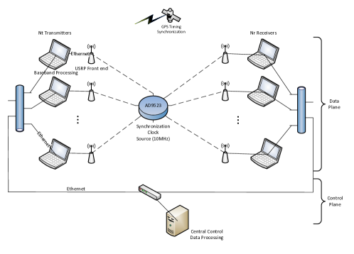
The massive MIMO system is composed of data plane and control plane, as depicted by Fig. 3. The data plane is responsible for the channel measurement and waveform data processing. On the data plane, 30 PCs are configured as baseband processing units. Every baseband processing unit is connected to arbitrary number of USRP front-ends acting as either transmitter or receiver, through Ethernet. On the control plane, one central control PC is connected with all the baseband processing units to control the procedures of the experiment including the start and stop of measurement, parameters configuration, etc. The communications between the baseband processing unit and control unit is also over Ethernet and the socket/TCP programming.
III-C Massive MIMO testbed over time division protocol
The channel matrix measurement is a challenging task that is achieved by our massive MIMO testbed. Firstly, we want to measure the data within the time frame that the channel can be regarded as static. Secondly, there are so many links () to be measured within this time frame. The orthogonality needs to be ensured that the measured result for each link is not interfered by all the rest of the links. We choose the time division method to separate the channel measurements for all the links. Under the time division strategy, our massive MIMO testbed is equivalent to a TDMA network. transmitters only send the PN sequence within their own time slots, while the mobile users can be set as receive only mode.
During the experiment, suppose the number of the transmitters is the same with the number of mobile users, so we actually deployed a MIMO system which is regarded as a massive MIMO testbed as the scale is much bigger than the current commercial MIMO system.
III-D Synchronization
The timing synchronization for all the TDMA nodes is achieved by the GPS signal as shown in Fig. 3. The timing precision provided by the GPS signal reaches nano-second, which is sufficient for the time slot scheduling. Every USRP is equipped with a dedicated GPS antenna that can feed the timing information to the front end. The baseband samples sent from the PC to the USRP can be arranged within the specified time frame for transmitting by adding the time tag information at the start of sample series.
We also provide the clock synchronization for all the USRP front-ends by the clock distributing board AD9523 as in figure. 3. The common clock between the transmitters and receivers helps to remove the carrier frequent offset(CFO) that is introduced by different clock sources.
IV Experiment results
This massive MIMO testbed can be scaled to at most . The measured channel matrix is used to calculate the real MIMO system capacity.
In the experiment, if we set the time slot duration to , we can get a round of TDMA data by for MIMO system. configuration costs to get a round of data. Basically the channel can be regarded as static within several seconds for our current static deployment because there no other impact during the experiment.
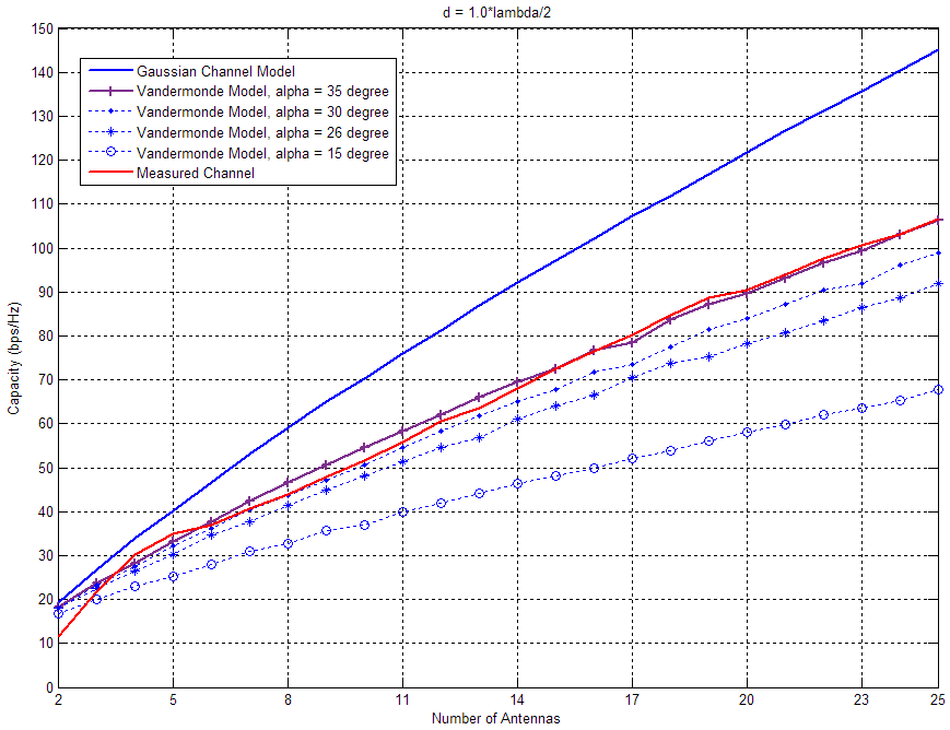
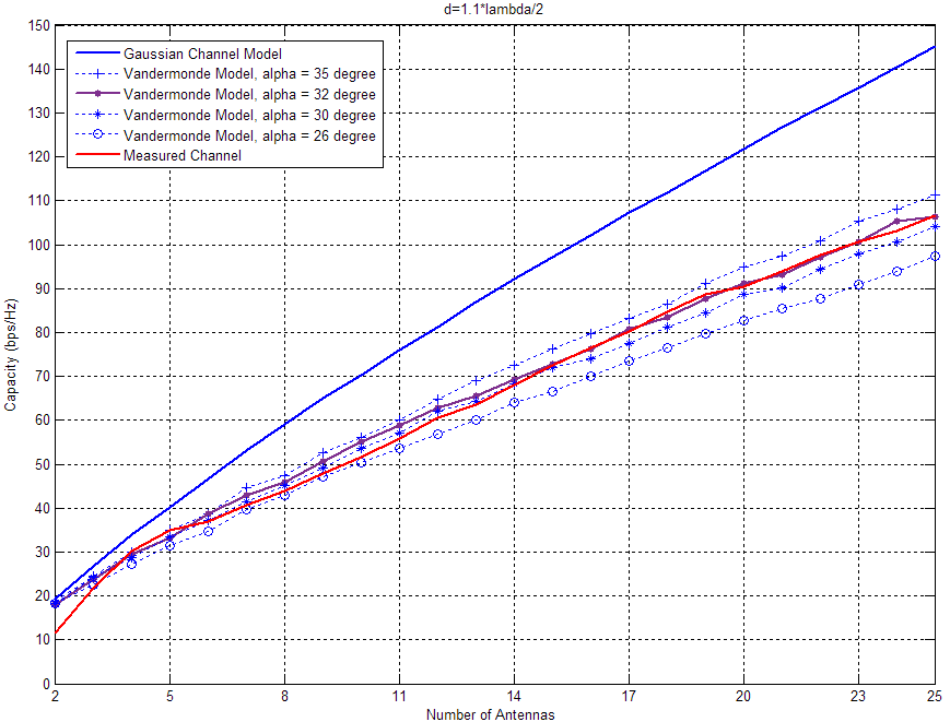
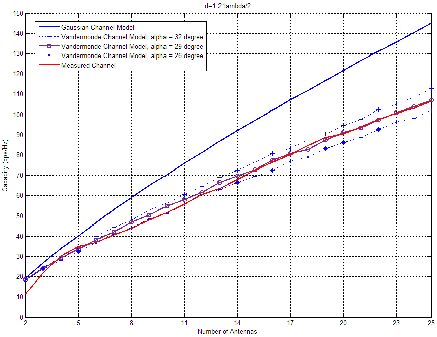
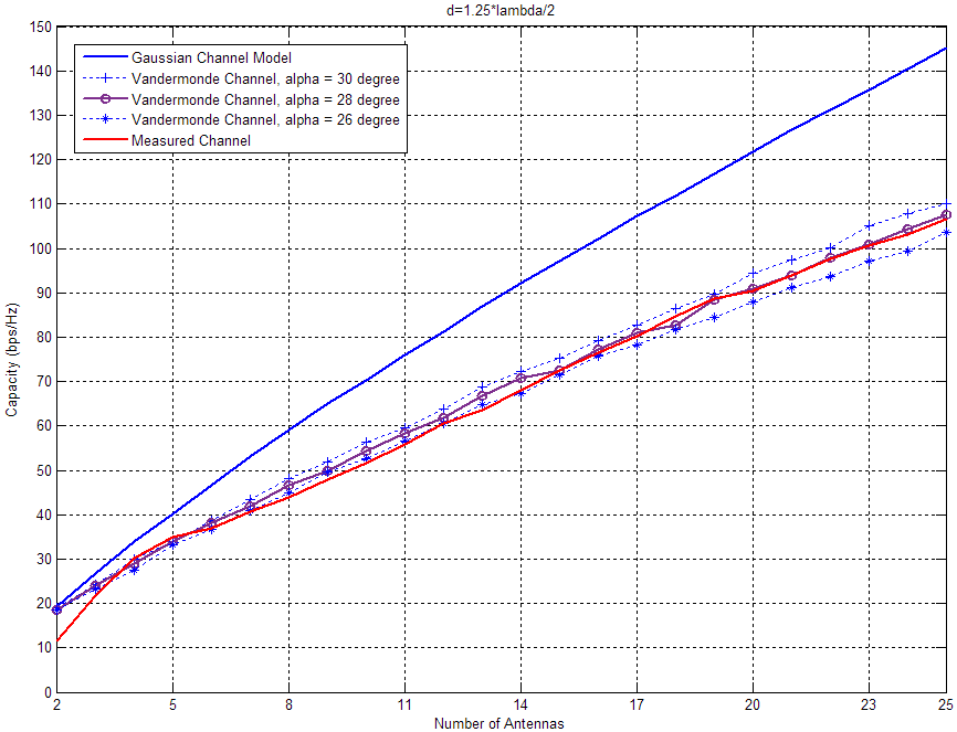
We did the simulations for the capacity under the Vandermonde channel model, by adjusting two parameters and based on section II-B. Fig. 4 shows the experimental results compared with the simulations. The experimental frequency is 926MHz, the corresponding wavelength is . The average distance between the adjacent nodes for base station is about . We selected the parameter in and did the simulation for Vandermonde model by adjusting for each fixed .
Firstly, we demonstrate the linearity of the capacity with the number of antennas by the measured channel capacity in Fig. 4. The capacity of the system increases linearly with the number of antennas, for both the simulated Gaussian channels, Vandermonde channels and the measured channels.
Secondly, we found the feasibility to fit the massive MIMO channel model to the Vandermonde channel model, by the comparison of capacities between the real channel measurement and the Vandermonde channel model. Fig. 4 shows observations including :
-
•
The capacity of Vandermonde channel decreases when is getting smaller for fixed .
-
•
The capacity of Vandermonde channel increases when is bigger for fixed .
-
•
For every fixed , we can find an to fit the Vandermonde model to measured channel in capacity with minimum mean error (MME). Table. I shows the MME value for different under each fixed . Bold represents the optimal for each .
We get insight from above that the Vandermonde channel model is more realistic than the Gaussian channel model in depicting the massive MIMO system. The Gaussian model does not reflect the topology of the real MIMO system while the Vandermonde model is more illustrative as the parameter and are contained. Also, the Gaussian model always has the ideal capacity which is hard to be achieved in the real system. We can always find an equivalent Vandermonde model for the measured massive MIMO channel by our real experimental data, when their capacities are very close under optimal pair of and .
In Table. I, the parameters pair (, ) with values of (, degree) gives the minimum MME value. This optimal parameters pair are very close to that in the real deployment (, degree).
| MME- | MME- | MME- | MME- | ||||
| 35 | 40.7338 | 35 | 86.2465 | 30 | 52.0346 | 30 | 77.9740 |
| 30 | 98.9845 | 32 | 39.7652 | 29 | 39.7046 | 28 | 37.9838 |
| 26 | 189.545 | 30 | 51.8876 | 26 | 66.8592 | 26 | 50.9662 |
V conclusion
This paper presents the design and implementation of a novel SDR based massive MIMO testbed using TDMA protocol. The MIMO channel matrix is measured through the experiment with the prototype of the testbed. The system capacity is computed from the measured channel matrix. The testbed is validated by the linearity of capacity with the increasing number of antennas. We also found that the measured channel capacity agrees with that of the Vandermonde channel model with the optimal parameters: the range of the arrival angles and the base station antenna distance which are very close to those in experimental deployment. It is the first time the feasibility of the Vandermonde channel model is shown in the real experimental result. Based on our work, we recommend the Vandermonde channel model to be used in future theorectical research, as it is more realistic than the current widely used Gaussian model.
References
- [1] F. Rusek, D. Persson, B. K. Lau, E. G. Larsson, T. L. Marzetta, O. Edfors, and F. Tufvesson, “Scaling up mimo: Opportunities and challenges with very large arrays,” Signal Processing Magazine, IEEE, vol. 30, no. 1, pp. 40–60, 2013.
- [2] F. Boccardi, R. W. Heath Jr, A. Lozano, T. L. Marzetta, and P. Popovski, “Five disruptive technology directions for 5g,” arXiv preprint arXiv:1312.0229, 2013.
- [3] S. Wagner, R. Couillet, M. Debbah, and D. T. Slock, “Large system analysis of linear precoding in correlated miso broadcast channels under limited feedback,” Information Theory, IEEE Transactions on, vol. 58, no. 7, pp. 4509–4537, 2012.
- [4] R. Couillet, M. Debbah, and J. W. Silverstein, “A deterministic equivalent for the analysis of correlated mimo multiple access channels,” Information Theory, IEEE Transactions on, vol. 57, no. 6, pp. 3493–3514, 2011.
- [5] O. Ryan and M. Debbah, “Random vandermonde matrices-part i: Fundamental results, ,” IEEE Transactions on Information Theory, 2008.
- [6] M. Debbah et al., “Random vandermonde matrices-part ii: Applications,” tech. rep., 2008.
- [7] G. H. Tucci and P. A. Whiting, “Eigenvalue results for large scale random vandermonde matrices with unit complex entries,” Information Theory, IEEE Transactions on, vol. 57, no. 6, pp. 3938–3954, 2011.
- [8] M. N. Islam, B.-J. J. Kim, P. Henry, and E. Rozner, “A wireless channel sounding system for rapid propagation measurements,” in Communications (ICC), 2013 IEEE International Conference on, pp. 5720–5725, IEEE, 2013.