Squeezout phenomena and boundary layer formation of a model ionic liquid under confinement and charging
Abstract
Electrical charging of parallel plates confining a model ionic liquid down to nanoscale distances yields a variety of charge-induced changes in the structural features of the confined film. That includes even-odd switching of the structural layering and charging-induced solidification and melting, with important changes of local ordering between and within layers, and of squeezout behavior. By means of molecular dynamics simulations, we explore this variety of phenomena in the simplest charged Lennard-Jones coarse-grained model including or excluding the effect a neutral tail giving an anisotropic shape to one of the model ions. Using these models and open conditions permitting the flow of ions in and out of the interplate gap, we simulate the liquid squeezout to obtain the distance dependent structure and forces between the plates during their adiabatic appraoch under load. Simulations at fixed applied force illustrate an effective electrical pumping of the ionic liquid, from a thick nearly solid film that withstands the interplate pressure for high plate charge to complete squeezout following melting near zero charge. Effective enthalpy curves obtained by integration of interplate forces versus distance show the local minima that correspond to layering, and predict the switching between one minimum and another under squeezing and charging.
pacs:
61.20.Ja,61.20.Qg,68.15.+e,68.08.-p,68.08.Bc,68.18.FgI Introduction
Ionic liquids (ILs), ionic salts based on organic molecules whose large size, amphiphilicity and anion-cation asymmetry generally yield melting below room temperature, encompass an enormous chemical variety Zhang et al. (2006), interesting physical properties Greaves et al. (2006), and numerous applications Plechkova and Seddon (2008). The structural and electrical properties of ILs near solid interfaces have been investigated experimentally Mezger et al. (2008); Hayes et al. (2011) and theoretically Bazant et al. (2011); Kornyshev (2007). Data show that under force-induced boundary confinement, the liquid undergoes strong layering Atkin and Warr (2007); Sweeney et al. (2012); Smith et al. (2013a); Li et al. (2014). Squeezout takes place for increasing force in bilayer steps, so that ions of opposite sign exit together, keeping overall neutrality. The electrical charge of the lubricant molecules and their layering under confinement naturally suggest the possibility to influence the layering, and the squeezout behavior, by means of plate charging or by otherwise applied fields. The charging of a gold surface in an IL filled narrow AFM gap indeed showed important frictional changes as a function of the applied voltage Sweeney et al. (2012). Different effects of charging have been reported in other experiments with different ILs Li et al. (2014). That confirms on one hand that charging is indeed an important parameter influencing structure, squeezout and friction, and on the other hand that the details of these charging effects generally depend upon the specific nature of the IL and of plates. It seems at this point important from a more general viewpoint to conduct a wider theoretical and simulation inquiry, exploring possible charging induced phenomena based on less specific, more generic, reasonably simple models. These models of course do not replace the much more specific systems currently being simulated to describe specific ILs and their confineb behavior Mendonca̧ et al. (2013); Canova et al. (2014). Simplicity of the model on the other hand is essential to allow a wide-angle view of some among the possible squeezout effects and scenarios provided by charging, either static or time-dependent, of the confining surfaces.
Within this broad exploratory program, and without aiming at modeling a specific case,
we investigate first of all the scenario of ILs confined between two neutral
or nearly neutral, then charged, solid plates. This study encompasses a variety of charging-related static phenomena,
preparatory to the dynamical study of frictional behaviour which will be considered in subsequent work.
As in the early approach of Fedorov and Kornyshev we begin with a simple charged Lennard-Jones system,
but then we extend it by the minimal addition of a neutral “tail” making one of the ions considerably
asymmetric, as is common in many real IL ions.
Using an open geometry, where ions can escape or re-enter the interplate gap during slow, adiabatic
changes of the interplate gap width , we observe in the simulation the formation of partly ordered layers
under squeezing. In analogy to experiments Hayes et al. (2011); Smith et al. (2013a) squeezout is found to take place by successive transitions
through plateaus at well defined interplate distances, through force-induced gap changes corresponding
to one IL bilayer, clearly the neutral entity here. This transverse layering structure is accompanied by some degree of lateral,
planar ordering inside each IL molecular layer. Planar order, even if probably overemphasized by our simple
models relative to much more complex real ILs (where in-plane spatial order is so far unaccessible experimentally)
is nonetheless a relevant feature that helps understanding both structure and dynamical behavior. We characterize
planar ordering of our confined IL by means of a k-space resolved structure factor, analogous to a two-dimensional,
z-resolved diffraction scattering amplitude.
Some level of frustrated plate- and confinement-induced 3D crystallization is also found, whose detailsare, as we show,
model-dependent. We extract by means of force-distance integration a very instructive effective interplate interaction
free energy, where the different plateaus appear as local minima, so that the squeezout transitions between
them is described and in fact predicted by a Maxwell construction.
The effect of charging is subsequently shown to cause structural changes
which can in turn be related to changes of the interplate equilibrium free energy
characteristics.
II Model and simulation geometry
ILs are molten salts usually made up of large-size anions and cations Zhang et al. (2006), generally organic,
and with asymmetric irregular shapes often including long alkyl chains. The irregularity is
important as it gives the molecule a larger gyration ratio in the liquid state, while effectively
preventing low temperature order and crystallization by replacing it with a glassy state.
Dropping most of these complications we restrict to a much simpler model, crudely including just
the rough features of a generic IL. We will therefore build on the basic model already exploited
in previous studies Fedorov and Kornyshev (2008), namely a charged Lennard-Jones (LJ) system where aniona and cations have different radii.
We compare this model with its extension, obtained by attaching a neutral ”tail” to the cation. In the extended model
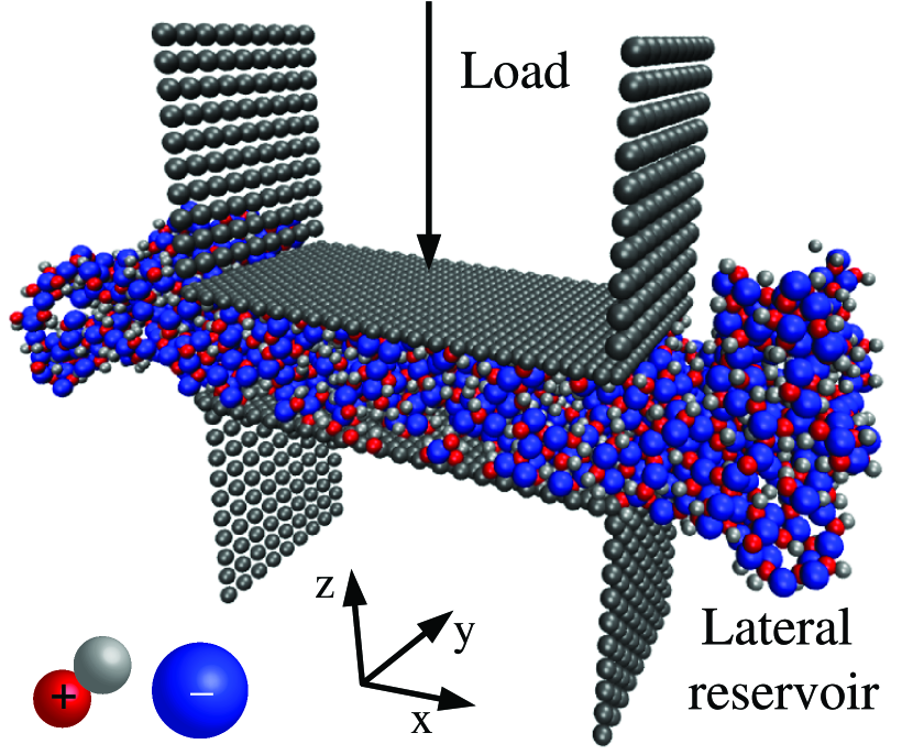
the anion consists of a negatively charged, large-sized spherical LJ classical particle, the cation of a dimer
made of a positively charged, small-sized LJ head, rigidly bound to an equal size, neutral particle, the tail
(see Fig. 1). The tail simultaneously achieves several goals. First, it enhances the liquid gyration
diameter, the solid-liquid density jump, and the general tendency to form a glass rather than a crystal at low temperatures.
Second, it improves the plate wetting behavior, which without tails is unrealistically strong, while the wetting
by real IL of surfaces such as mica is only partial Wang and Priest (2013). Partial wetting is plausibly
associated, at least in some cases, with a first monolayer of cations whose outward pointing tails may provide
a “phobic” gap against further layer-by-layer film growth. That is realized in
our “tailed” model (TM) but not in the simpler charged LJ ”salt-like” (SM) model. Finally
the tail also introduces rotational entropy effects that must be present in real systems,
but are missing in simple SMs Fedorov and Kornyshev (2008); Fumi and Tosi (1964); González-Melchor et al. (2005).
Building on the work of Fedorov et al. Fedorov and Kornyshev (2008), we thus assume the anion (A), the positive head of the cation (C) and plate ”atoms” (P) to interact electrostatically and via a LJ potential
| (1) |
with . The tails (T) interact with all other species through a repulsive potential
| (2) |
with . The full list of parameters is reported in Table 1. We adopt the LJ potential strengths as our energy unit and take ion-plate radii slightly smaller than those between ions in order to provide a reasonable wetting habit of the plates. The SM consists of the same model liquid simply without the tail, as used in Fedorov and Kornyshev (2008). To account for the dielectric screening of real systems, the two ionic species of charge + and - ( the electron charge) are immersed in a uniform average dielectric with .
| AA | 1 | 1.3 |
| CC | 0.5 | 1.3 |
| AC | 0.75 | 1.3 |
| AP | 0.7 | 13 |
| CP | 0.35 | 13 |
| TT | 0.5 | 1.3 |
| TA | 0.75 | 1.3 |
| TC | 0.5 | 1.3 |
| TP | 0.35 | 13 |
The liquid is confined between two negatively charged plates with a modest surface charge density , unless
differently specified, chosen to break the charge symmetry. The plates (somewhat similar to mica surfaces used in SFA experiments)
are made of LJ sites arranged in a rigid close-packed triangular lattice with spacing 0.52 nm.
All
molecular dynamics (MD) simulations were performed using the LAMMPS code Plimpton (1995).
Canonical ensemble configurations were sampled by means of a Langevin thermostat
directly applied to the lubricant molecules. The plates were treated as rigid bodies,
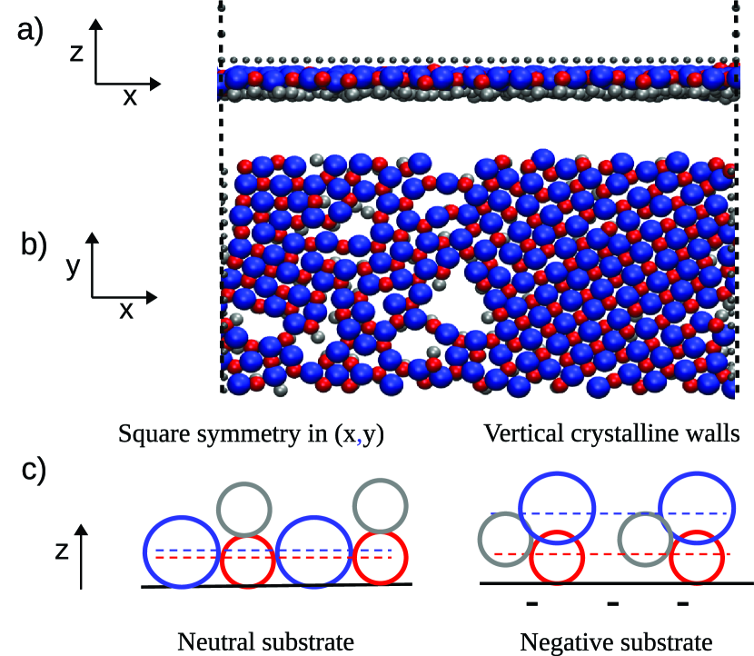
the lower one fixed and the upper one either subjected to a z-directed force (the load) as
shown in Fig. 1, or else driven along , inwards or outwards, at some very small constant velocity.
While the total number of simulated ions is constant, the finite plate width along ending with free vacuum on both sides
in the simulation cell geometry (Fig. 1), permits, unlike other IL simulations, otherwise
very realistic, Canova et al. (2014); Mendonca̧ et al. (2013) particle squeezout with formation of two lateral ionic liquid
drops. The drops serve as liquid reservoirs so that the number of ions effectively confined inside
the gap can dynamically change depending on the loading conditions, realizing an effectively grand-canonical situation.
III Bulk melting and solidification
A basic property of an IL is its melting habit. We
investigate and compare the bulk melting temperature of the TM and SM models by performing
a slow-varying temperature loop MD simulation of both models with ions and full 3D periodic
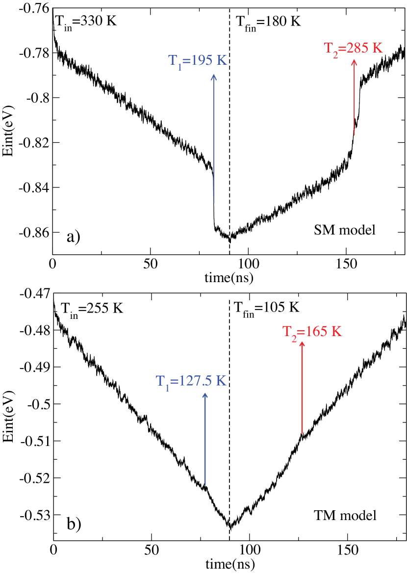
boundary conditions. Starting from a high temperature , where both SM and TM
are in the liquid state, we
first decrease the temperature to
a much lower with a rate of , producing solidification; then increase it again back
to , to produce melting .
Fig.2a shows the internal energy, of the SM inthe temperature loop.
On cooling, linearly decreases
until a sharp drop at corresponding to a liquid-solid transition.
On heating back the solid a sharp rise of is found at , corresponding
to the reverse solid-liquid transformation. The large magnitude of jumps reflects strong crystalline order
in the SM solid. The equilibrium melting temperature is to be foumd between those of internal energy drop
and rise, whose difference reflects the hysteresis normally encountered in the absence of nucleation centers, such as surfaces.
The TM behaves similarly, but displays smoother transitions, reflecting a much poorer ordering in the solid,
and lower transition temperatures
and , as shown in Fig. 2b.
In both SM and TM these transitions are
accompanied by correspondingly strong changes of diffusion coefficient (not shown). If we assume arbitrarily that
the melting temperature is the average between and , we obtain
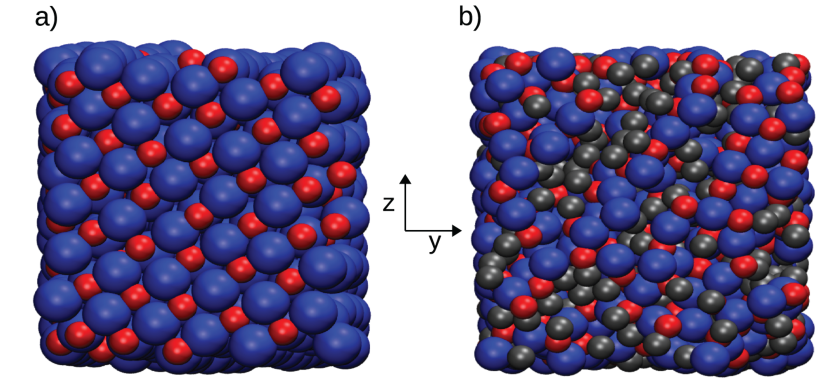
for TM and for SM respectively. The decreased density
of TM relative to SM reduces the cohesive energy and thus the melting temperature. The tails in TM also
prevent crystallization in the rocksalt structure typical of SM as shown in Fig.3.
Unless otherwise specified, all simulations reported in the following were done at
temperature and for the TM and SM respectively, safely above
but not too far above the bulk melting temperatures, as in real experimental cases. In our simulations
therefore both ILs are in a fully liquid state as long as the gap width between the two plates is sufficiently large.
Both ILs may solidify, as we will show, when the confining gap between plates is reduced down to the
molecular thicknesses typical of boundary lubrication conditions.
IV Wetting properties
The wetting of plate surfaces such as mica is known to be partial by at least some
ILs Beattie et al. (2013); Wang and Priest (2013). Squeezout phenomena and layering necessarily involve
intimate features of the liquid-solid plate interface,
not disconnected with those determining the plate wettability. Thus it is important to monitor the plate wetting habit of our IL models.
To do that, we simulate for both models the behaviour of a liquid droplet
consisting of ions
deposited on a neutral and then on a lightly charged plate. The adhesion parameters of
the liquids should be chosen in a reasonable way and in order to reproduce qualitatively
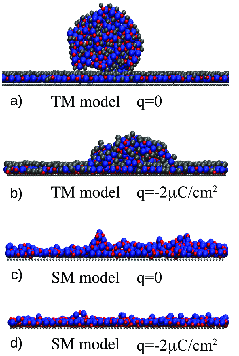
the wetting properties. We find (Fig.4) that the TM wetting of the neutral plate is poor, forming a wetting angle .
On the contrary, the SM completely wets the substrate. Only in the TM the cations provide
outwards pointing tails, which give rise to a ”phobic” gap, responsible for the incomplete wetting, see Fig.4a.
Upon charging of the plates, one expects wetting to be generally enhanced Welters and Fokkink (1998); Paneru et al. (2010)
for either sign of charge, over the neutral case.
For moderately negative charging we find that the TM liquid indeed
wets better than in the neutral case, yielding a smaller wetting angle .
The charging evidently reduces the effect of tails, and their effective screening of electrostatic forces.
For a moderatly positive charge on the other hand, the TM wetting angle is slightly
larger than negatively charged substrate. This asymmetry is due to the different size and shape of ions.
These TM results – monolayer coating, partial wetting by the drop – are in qualitative agreement
with experimental data Beattie et al. (2013); Wang and Priest (2013) for 1-butyl-3-methyl-imidazolium bis-(trifluoromethylsulfonyl)imide,
[BMIM] [TFSI], on mica,
which show a precursor layer forming ahead of a macroscopic drop with .
This partial wetting scenario is absent, and replaced by complete wetting in the SM.
Thus, in such simplified modeling, the introduction of neutral repulsive tails,
mimicking, e.g., alkyl chains in real IL systems, turns to be important for the correct wetting properties of the IL.
It is highly reasonable to presume that this important element of realism will be important in future
studies of sliding friction.
V Squeezout simulations and layering
Liquids close to hard surfaces display, both experimentally
and theoretically, spatial structuring phenomena with respect to their uniform bulk density. When a liquid film is confined
in a planar gap between hard plates a few molecular diameters wide,
it develops quite generally a layered density profile Israelachvili (2011), with increasing solid-like properties that eventually
enable it to resist squeezout and to support static friction. The squeezout of these layers one at a time
under increasing load is well studied theoretically Persson and Tosatti (1994); Gao et al. (1997); Tartaglino et al. (2002, 2006)
and experimentally Mugele and Salmeron (2000); Zilberman et al. (2001).
Similar to common liquids, ILs generally give rise to partially ordered molecular-size layers and
enhanced viscosity at interfaces with solid surfaces such as mica, silica, and gold Ueno et al. (2010); Smith et al. (2013b); Atkin and Warr (2007); Atkin et al. (2009).
For reasons of charge neutrality and compatibly with ion asymmetry, ILs organize themselves in alternating positive and negative layers
not too far from the plates.
The squeezout between approaching plates occurs in this case by neutral entities, that is by pairs of layers,
as seen in all experiments, as also described by a recent theoretical model Hoth et al. (2014).
Depending on the specific IL, its melting temperature and its relationship to
the confining surfaces, experimental
squeezouts by sharp AFM tips may require relatively large applied forces from some nN
to several tens of nN Hayes et al. (2011) which, for an area in the order of 1-10 nm2
gives an indication of the strength of interactions involved.
The available simulations of confined ILs are carried out under unrealistic sealed conditions, via periodic boundary constraints Mendonca̧ et al. (2013); Canova et al. (2014), which do not permit squeezout. Experimental SFA and AFM setups constitute eminently open geometries, allowing dynamical liquid squeezout and suck-in. For our simulations we therefore adopt an open geometry, albeit a very simple and schematic one. As shown in Fig.1 it consists of two rigid plates that are infinite along , but finite along , with the IL filling the gap between them. When the plates are moved closer to one another, the liquid is squeezed out of the gap, flowing sideways to form two side drops that constitute IL reservoirs. A simulation geometry similar to ours was used by Landman’s group Gao et al. (1997) whereas a different open geometry allowing for squeezout was adopted by Tartaglino et al. Tartaglino et al. (2006). Open simulations were also recently used to investigate squeezout and phase transition of an argon film between two solid surfaces Yongsheng Leng and Rao (2013). In our initial protocol the plates were very slowly approached, and the resulting average force on the top plate, , was monitored as a function of the diminishing inter-plate distance . Beginning for example with a TM bulk liquid confined between plates and closing gradually the gap width , remains initially zero while the liquid is readily expelled, until a critical distance is reached between plates, , amounting to a few bilayers, where the force-distance curve departs significantly from zero and begins to grow. The growing force between the plates shows layering oscillations as in Fig.5. Each force dip corresponds to the complete squeezeout of a pair of layers, one positive and one negative, as in experiment Hayes et al. (2011); Smith et al. (2013a). If the plate motion is inverted, now increasing the gap width with time, the squeezout is replaced by ”suck-in” of the IL. The black and the blue force curves of squeezout and suck-in are not identical at a given distance, and form a narrow hysteresis loop. The area enclosed in the force-displacement loop measures the dissipation work implied by our plate to-and-from motion, exerted at small but not infinitesimal speed. Were the plate speed to tend to zero (quasi-static limit), dissipation would vanish, and the two force-distance curves would collapse onto a single adiabatic force at all finite temperatures. In these conditions the adiabatic work provides an accurate measure of the interaction free energy between the plates. Layering oscillations of this distance-dependent free energy was earlier demonstrated in simulations of simple liquids Gao et al. (1997).
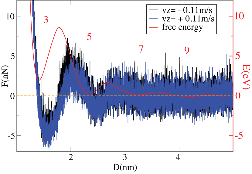
Changing from fixed distance to fixed force, where a normal load, , is applied to the top plate,
and the interplate distance is observed to vary as a consequence, these free energy curves establish a relation between
and the consequent number of confined layers. For example,
when only two metastable states with 3 or 5 layers are allowed, while at all states are allowed.
That concept was recently underlined by Hoth et al. Hoth et al. (2014).
The number of confined layers between identical plates is odd, as is demanded by symmetry.
Confinement of ILs between mica plates offers a direct example of odd layering Smith et al. (2013a)
due to the symmetrically slightly negative charge of both plates, each of which attracts a similar coating
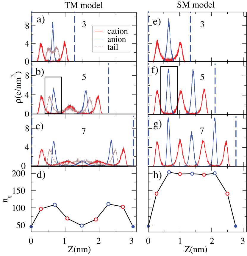
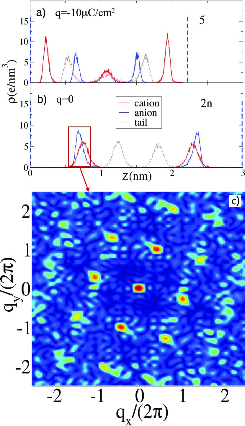
of cations. The ”transverse” density profile measured along the vertical, plate-to-plate z axis shows a clear
oscillatory order with cations and anions populating different, well separated layers. In the TM in addition, the
light brown line represents the density of tails (Fig.6a,b,c). The positions of cation and anion peaks closest
to the plates (vertical blue dashed lines), are geometrically related to their radii. As the number of layers increase,
all oscillations broaden and weaken, more so in the TM due to the disordering effect of tails.
The SM liquid presents a qualitatively similar picture, where the absence of tails and related disorder
allows much more pronounced layering order, occurring at a larger distance between the plates.
The force needed to squeeze out a pair of SM layers is much larger, and the peaks of density
profile along vertical axis more pronounced, as shown in Fig.6e,f,g.
The bottom panels in Fig.6d,h display, in the case of seven layers, the number of charges per layer, , with total charge per layer and electron charge. The total amount of charge, including the plates and the confined liquid, preserves electroneutrality. The TM shows a clear overscreening, with the charge of layers in contact with plates substantially larger than far away. Due to confinement, the SM liquid shows a much readier tendency to solidify. The charge plateau in Fig.6h indicates precisely a crystalline region where a well defined number of ions per layer is required for a rocksalt structure with (111) planes parallel to the plates.
VI Layer-resolved planar structure, 2D structure factors; 3D structures, crystallization phenomena
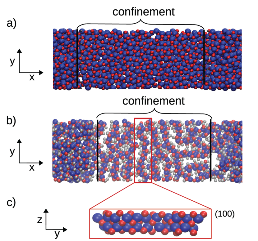
The simulation temperatures, substantially but not excessively above the bulk melting temperature, ( and for TM and SM respectively) preserve a reasonably large amount of short range order in the IL. That short range order naturally emerges near hard plates, and yields both transverse and planar static order in the layered structure of the liquid confined between the plates. That order is associated with some partial solidification, and indeed when the gap width decreases below a distance corresponding to 10 molecular diameters, both SM and TM layered ILs increasingly resist squeezout. Accompanying the layering, there must be some amount of planar ordering. Contrary to layering, well known and clearly reflected by squeezout experiments, the planar order is so far experimentally undetected. Fig.7a and 7b show top views of SM and TM liquids for corresponding to five confined layers, revealing the nature and extent of planar order. The SM liquid has ordinary molten salt short-range order, eventually tending to (111) rocksalt planes parallel to the plates. The effect of tails on planar order is quite strong. Unlike the SM, the TM liquid forms wall-like structures, which transversely straddle the gap between the plates. Ions of opposite charge arrange in charge-ordered planes parallel to z, with wide gaps between them occupied by the tails, randomly protruding on either sides. While keeping reasonably parallel at short range, these walls are rarely straight, and generally tend to meander as the figure shows. Similar wall-like (sometimes described as worm-like) patterns of unspecified heigth were reported in AFM pictures of ILs on gold Atkin et al. (2009); Borisenko et al. (2006); Lin et al. (2003) and mica Segura et al. (2013).
For a more precise characterization of planar order, we calculated the z-resolved structure factor per layer, defined as
| (3) |
where is the position of particles with coordinate in a window close to , is the number of particles in that window, and indicates time average. The z-resolved of the window enclosed in the black rectangle in Fig.6f shows that anions approximately form a 2D triangular lattice, indicating that the SM liquid crystallizes in a rocksalt structure with a (111) plane in contact with the plate (see Fig.8a).
The confined TM film behaves in this respect quite differently from SM. The layer structure factor of the TM anion layer enclosed in the square of 6b, displays a liquid-like structure factor, caused by random orientation of wall-like structures (see Fig.8b).
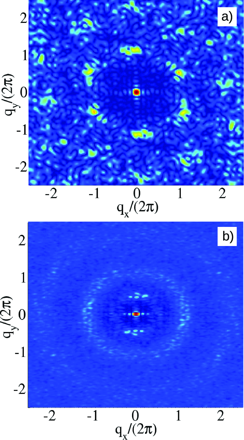
Away from the plates the layering is less pronounced, and there the TM liquid
shows a tendency to appear organized with a 2D triangular lattice symmetry.
Fig.7c shows a side view of the single vertical wall
indicated by the red square in Fig.7b, where tails have been
removed from the picture for clarity. The (100) plane of rocksalt is easily recognized.
Because of the random orientation of tails, the liquid cannot solidify in a complete three-dimensional
crystal, but it manages to arrange in vertical neutral rocksalt walls with tails segregated
in the spaces between adjacent walls and oriented parallel to the plates.
These two examples suggest some more general understanding, that may be valid beyond the two specific cases. First, plate-induced layering and charge neutrality are universal, as was to be expected. Second, the detailed nature of planar and of three-dimensional ordering, ranging from nearly crystalline to glassy, is variable and much more dependent upon the specific nature of the IL consituents.
VII Symmetric plate charging
The properties of plate-confined ILs described so far for neutral or nearly neutral plates are strongly
disturbed once the plates are electrically charged. We study first the
structural and squeeezout
behavior under symmetrically charged plates, that is both plates with same charge density .
In order to preserve the overall system neutrality in simulation, we simultaneously remove from the liquid a number of ions
amounting to the compensating charge . Upon increasing negative on both plates, the confined IL
acquired a more solid-like structure, which is mechanically stronger and can bear higher loads before being squeezed out.
Fig.9a shows a force-distance curve for the TM liquid, with a charge density
of on both plates. The force-distance curve show much higher peaks than for neutral plates as in
in Fig.5, signaling the larger force needed for squeezout from to layers.
The SM has a very similar behavior, with even higher peaks in the force-distance curve (not shown).
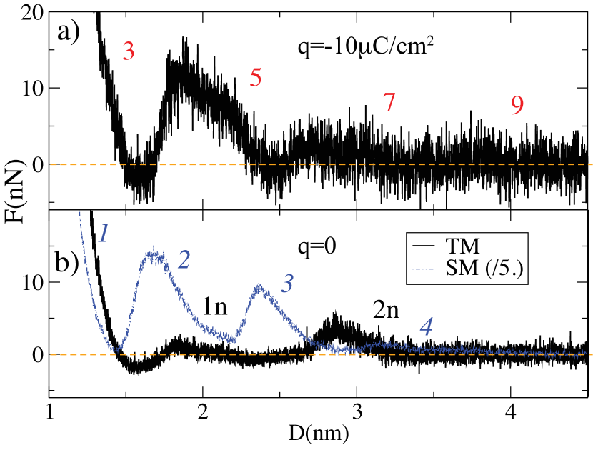
Fig.10a shows the density profile along the z direction for five TM confined layers between negative plates. Cations crowd up near the negatively charged plates, their tail protruding away from the plates.
For totally neutral plates however, in presence of the sole adhesion forces between
ions and plates, the structure of the two model liquids differs rather drastically.
The force-distance curve for the more realistic TM liquid displays just two peaks and no
evidence for extended layering (see Fig.9b). With neutral plates
the IL cannot support the 1 nN load down to a gap width of .
A qualitatively similar picture also emerged in recent experimental investigations showing how surface charges affect the molecular
structure and flow properties of ILs Bou-Malham and Bureau (2010).
The transverse density profile for and
is shown in Fig.10b with formation of just two
neutral layers (which we denote as 2n) where both anions and cations coexist in
a single monolayer, which is bound to the plate by short-range adhesion.
The cation tails point outward from the plate giving rise to a weakly repulsive coating,
which hinders further layering, as suggested by a side view in Fig.11a.
By further increase of vertical load, one of the two neutral monolayers is further squeezed out
leaving a single one (indicated with 1n) residually confined between the plates.
The planar structure of these layers is interesting. Fig.11b presents a top view of a single layer for the state 2n.
In contrast to the case of charged plates, where the IL crystallized with wall-like z-oriented planes,
neutral plates induce ions to form neutral layers with square symmetry as shown by Fig.10c.
Such charging-induced structural transitions may indeed generally arise from a competition between electrostatic and adhesive forces.
In our case, the sole adhesion to neutral plates binds both cations and anions to the plate, so that they arrange in a rocksalt (100)
monolayer with tails pointing outward. A negative plate instead selectively binds
cations but not anions, giving rise to an alternation of positive and negative layers with tails parallel
to the plates. A pictorial representation of these charge induced structural
transitions is given in Fig.11c.
The SM IL also undergoes a charge induced structural transition, from a triangular to a square arrangement in presence of neutral plates. Much more ordered than the TM, it displays extended layering, as show by blue dotted line in Fig.9b. Essentially, it solidifies in a rocksalt crystal with the (100) surface in contact with the neutral plate. Each peak of the blue curve in Fig.9b, corresponds to the squeezout of a single neutral (100) layer.
Noteworthy as they may be, these planar structure features seem presently unaccessible to experiments, and the development of techniques that could allow their study would be very interesting. In ordinary electrolytes, voltage-controlled phase transitions at electrode-electrolyte interfaces have been proven and studied in past years Kornyshev and Qiao (2014).
VIII Antisymmetric, time-dependent plate charging
In this section we finally study how the order in the TM liquid is affected by opposite charging of the two plates. The charging is given a slow sinusoidal variation with time, such as would be caused by externally driven plate charging with a sufficiently low AC frequency to ensure that all the ionic motion caused inside the interplate gap occurs on a much faster time scale. In this respect, we have checked there is enough adiabaticity to ensure that the effects of charge transport and heat dissipation are safely taken care of. Still, as we shall see, some notable non-adiabatic effects persist, connected with charge-induced solidification. By keeping the load constant at , the charging period and magnitude we simulate the spontaneous evolution of the confined IL and obtain the results shown in Fig.12.

Symmetry demands that the equilibrium layering structure for antisymmetric plate charging should occur
with an even number of players, whereas with symmetric charging the layer number was odd.
The simulation begins with a charge density of on plates and the IL structured
in six layers, which is the stable configuration under the fixed applied load force .
As the plate charge slowly drops in
time, the IL structure gradually changes and softens. Eventually, the IL becomes soft enough and squeezout
suddenly takes place, despite the constant load. The interplate distance drops, the IL film structure reaching a single,
charge neutral two-component layer branded , (see inset of Fig.12a and Fig.13c)
when =0. That structure is a history dependent state that forms asymmetrically depending upon the initial sign of the charge.
As the charging grows again now with inverted sign, the IL is sucked back in and both the gap width and the number of confined
partcles in the gap, , grow back to four layers with reversed charge order.
Although four layers is not, as we shall show later, the lowest free enthalpy state, which is instead six layers,
the metastable four layer state is nearly solid. In that state the kinetics becomes very slow,
so that the time needed to suck back in another bilayer becomes much longer than the simulation time.
As shown in Fig.12a,b the charging driven inter-plate breathing cycles
continue periodically, and so does the effective electro-pumping of ions in and out of the gap.
This kind of charging dependent phenomena based on spontaneous sucking in of the liquid, solidification
at large charge with buildup of a solid-like resistance to squeezout, followed by sudden squeezout
associated with melting of the confined layers upon charge reversal is very likely a more general
feature that could occur in a larger class of ILs beyond our simple model.
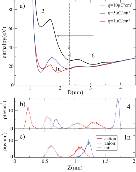
The charging induced transitions just observed in simulation can actually be predicted by the free enthalpy
of the system, , where is calculated the same way as earlier by integrating the interplate force
from infinity to the gap width . Fig. 13a shows the free enthalpy curves so obtained
as a function of for three values of the plate charge density , starting with six layers
which is the lowest free enthalpy configuration at a charge density .
Calculated curves show that upon decreasing the energy barriers between states at
different number of layers decrease gradually, eventually pushing the metastable six-layer state
leftward to a much smaller distance between plates. A dramatic squeezout event takes place
near (see Fig.12a), with a jump to the single layer state .
The successive reversal and increase of plate charge provokes the opposite transition at
where, as described in the previous section, the IL is sucked in, and structures up into four layers. As the charge
rises again to , the IL never returns to the equilibrium six layer state, indicating that
the thermal fluctuations and the simulation time are not sufficient to negotiate the four-to-six-layer
free enthalpy barrier (see Fig.13a black curve).
The nearly solid four layer state effectively resists the insertion of the last bilayer, and blocks the system in a metastable
state which is very long-lived, at least on our simulation time scale. The six-layer equilibrium state should of course be recovered
in a sufficiently slow charge dynamics.
Similarly to the TM, the SM IL shows even more dramatic charge induced squeezouts, followed by successive relayerings. The occurrence of dramatic electro-squeezout occurring under constant load due to the charge-induced boundary solidification of the IL and its sudden melting when the charge is removed, is quite likely a general characteristics that should be explored in real ILs.
IX Voltage behavior between plates
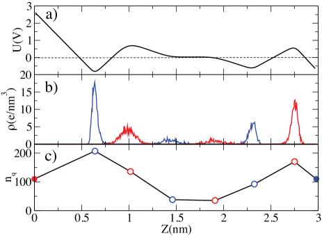
The plate-confined IL also has interesting capacitive properties. The antisymmetric plate charging described in the previous section corresponds to the application of a voltage between the plates. Assuming a uniform charge density in the plane, and integrating Poisson’s equation along the vertical axis we obtain an analytical expression for the voltage as a function of the coordinate between the plates:
| (4) |
where is the dielectric permeability of vacuum, is the density along vertical axis , and the second term is the contribution from surface charge density, , on the plates. Numerical values of calculated from the simulation are integrated to obtain the voltage profile, . Fig.14a shows the variation of voltage for a charge density and six IL layers confined, in full thermodynamic equilibrium, between the plates. We find that while the potential drop in vacuum would be , while in the presence of TM liquid . Moreover, remains nearly constant near the center of the film, showing that the TM liquid effectively screens the plate charge at short distance, as expected from the short Debye screening length of the bulk TM. Fig.14b is the density profile along vertical axis, while panel 14c displays the average total charge per layer. The color of circles refers to cations (red) and anions (blue), while the full circles indicate the plate charge in terms of electron charge , with area of plate. The total amount of charge, including the plates and confined liquid, is zero, preserving neutrality. The behavior vs shows a clear overscreening, a phenomenon well known in electrowetting Fedorov and Kornyshev (2008) with the charge of layers in contact with plates about twice larger than that on the plates.
X Discussion and conclusions
We have undertaken a detailed simulation study of the behavior of simple model ionic liquids confined between plates that are being pressed together producing squeezout. We studied that without and with electrical charging of the plates, showing that charging influences both the structure of the liquid and its squeezout behavior. Odd-number layering and near solidification is found between equally charged plates, from where squeezout occurs by successive expulsion of neutral bilayers, as is commonly observed in experiments. The intimate structure of the confined film is analysed, showing interesting types of planar order besides the known transverse layering order. To investigate the effect of plate charging with opposite sign, where the layering switches from odd to even, we carried out slow dynamics simulations where the distance between oppositely charged plates is very slowly and periodically varied as a function of time. Electrically driven squeezout and suck-in transitions are found and shown to give rise to a peculiarly fast electro-pumping, which works at constant applied load force, and is simply caused by the charging-induced solidification and melting of the IL. These phenomena are fully explained thermodynamically in terms of transitions between free enthalpy minima, which as shown by explicit calculations based on force integration are directly charging-dependent.
Although the simplicity of the models permits only a limited connection with existing data, the present study demonstrates a variety of phenomena that can and will take place when real ionic liquids are confined under charged plates. The striking effectiveness of the charging induced solidification-melting process with consequent ”electroequeezing” discovered in simulation might have practical applications.
Finally, the strong control exerted on the IL nanostructure by the charging of plates suggests that the lubrication of plate sliding sliding should be equally affected. That will be the subject of our forthcoming study.
XI Acknowledgments
The authors are grateful to D. Passerone and C. Pignedoli of EMPA (Dübendorf, CH) for the computational resources and the technical assistance provided, and to A. Kornyshev for helpful discussions. Work in Trieste was sponsored by ERC Advanced Grant 320796 - MODPHYSFRICT, and in part by Sinergia Contract CRSII2136287/1 and by COST Action MP1303.
References
- Zhang et al. (2006) S. Zhang, N. Sun, X. He, X. Lu, and X. Zhang, J. Phys. Chem. Ref. Data 35, 1475 (2006).
- Greaves et al. (2006) T. L. Greaves, A. Weerawardena, C. Fong, I. Krodkiewska, and C. J. Drummond, J. Phys. Chem. B 110, 22479 (2006).
- Plechkova and Seddon (2008) N. V. Plechkova and K. R. Seddon, Chem. Soc. Rev. 37, 123 (2008).
- Mezger et al. (2008) M. Mezger, H. Schröder, H. Reichert, S. Schramm, J. S. Okasinski, S. Schöder, V. Honkimäki, M. Deutsch, B. M. Ocko, J. Ralston, M. Rohwerder, M. Stratmann, and H. Dosch, Science 322, 424 (2008).
- Hayes et al. (2011) R. Hayes, N. Borisenko, M. K. Tam, P. C. Howlett, F. Endres, and R. Atkin, J. Phys. Chem. C 115, 6855 (2011).
- Bazant et al. (2011) M. Bazant, B. Storey, and A. Kornyshev, Phys. Rev. Lett. 106, 046102 (2011).
- Kornyshev (2007) A. A. Kornyshev, J. Phys. Chem. B 111, 5545 (2007).
- Atkin and Warr (2007) R. Atkin and G. G. Warr, J. Phys. Chem. C 111, 5162 (2007).
- Sweeney et al. (2012) J. Sweeney, F. Hausen, R. Hayes, G. B. Webber, F. Endres, M. W. Rutland, R. Bennewitz, and R. Atkin, Phys. Rev. Lett. 109, 155502 (2012).
- Smith et al. (2013a) A. Smith, K. Lovelock, N. Gosvami, T. Welton, and S. Perkin, Phys. Chem. Chem. Phys. 15, 15317 (2013a).
- Li et al. (2014) H. Li, R. J. Wood, M. W. Rutland, and R. Atkin, Chem. Commun. 50, 4368 (2014).
- Mendonca̧ et al. (2013) A. Mendonca̧, A. Pàdua, and P. Malfreyt, J. Chem. Theory Comput. 9, 1600 (2013).
- Canova et al. (2014) F. F. Canova, H. Matsubara, M. Mizukami, K. Kurihara, and A. L. Shluger, Phys. Chem. Chem. Phys. 16, 8247 (2014).
- Fedorov and Kornyshev (2008) M. Fedorov and A. Kornyshev, J. Phys. Chem. B 112, 11868 (2008).
- Wang and Priest (2013) Z. Wang and C. Priest, Langmuir 29, 11344 (2013).
- Fumi and Tosi (1964) F. G. Fumi and M. P. Tosi, J. Phys. Chem. Solids 25, 31 (1964).
- González-Melchor et al. (2005) M. González-Melchor, F. Bresme, and J. Alejandre, J. Chem. Phys. 122, 104710 (2005).
- Plimpton (1995) S. Plimpton, J. Comp. Phys. 117, 1 (1995).
- Beattie et al. (2013) D. A. Beattie, R. M. Espinosa-Marzal, M. N. P. Tracey T. M. Ho, J. Ralston, C. J. E. Richard, P. M. F. Sellapperumage, and M. Krasowska, J. Phys. Chem. C 117, 23676 (2013).
- Welters and Fokkink (1998) W. J. J. Welters and L. G. J. Fokkink, Langmuir 14, 1535 (1998).
- Paneru et al. (2010) M. Paneru, C. Priest, R. Sedev, and J. Ralston, J. Am. Chem. Soc. 132, 8301 (2010).
- Israelachvili (2011) J. N. Israelachvili, Intermolecular and surface forces, 3rd ed. (Academic Press, San Diego, CA, 2011).
- Persson and Tosatti (1994) B. N. J. Persson and E. Tosatti, Phys. Rev. B 50, 5590 (1994).
- Gao et al. (1997) J. P. Gao, W. D. Luedtke, and U. Landman, J. Chem. Phys. 106, 4309 (1997).
- Tartaglino et al. (2002) U. Tartaglino, B. N. J. Persson, A. I. Volokitin, and E. Tosatti, Phys. Rev. B 66, 214207 (2002).
- Tartaglino et al. (2006) U. Tartaglino, I. M. Sivebaek, B. N. J. Persson, and E. Tosatti, J. Chem. Phys. 125, 014704 (2006).
- Mugele and Salmeron (2000) F. Mugele and M. Salmeron, Phys. Rev. Lett. 84, 5796 (2000).
- Zilberman et al. (2001) S. Zilberman, B. N. J. Persson, A. Nitzan, F. Mugele, and M. Salmeron, Phys. Rev. E 63, 055103(R) (2001).
- Ueno et al. (2010) K. Ueno, M. Kasuya, M. Watanabe, M. Mizukami, and K. Kurihara, Phys. Chem. Chem. Phys. 12, 4066 (2010).
- Smith et al. (2013b) A. M. Smith, K. R. J. Lovelock, N. N. Gosvami, P. Licence, A. Dolan, T. Welton, and S. Perkin, J. Phys. Chem. Lett. 4, 378 (2013b).
- Atkin et al. (2009) R. Atkin, S. Z. E. Abedin, R. Hayes, L. H. S. Gasparotto, N. Borisenko, and F. Endres, J. Phys. Chem. C 113, 13266 (2009).
- Hoth et al. (2014) J. Hoth, F. Hausen, M. H. Müser, and R. Bennewitz, J. Phys.: Condens. Matter 26, 284110 (2014).
- Yongsheng Leng and Rao (2013) Y. L. Yongsheng Leng, Yuan Xiang and Q. Rao, J. Chem. Phys. 139, 074704 (2013).
- Borisenko et al. (2006) N. Borisenko, S. Z. E. Abedin, and F. Endres, J. Phys. Chem. B 110, 6250 (2006).
- Lin et al. (2003) L. Lin, J. Y. Y. Wang, Y. Yuan, J. Xiang, and B. Mao, Electrochemistry Communications 5, 995 (2003).
- Segura et al. (2013) J. J. Segura, A. Elbourne, E. J. Wanless, G. G. Warr, K. Voïchovsky, and R. Atkin, Phys. Chem. Chem. Phys. 15, 3320 (2013).
- Bou-Malham and Bureau (2010) I. Bou-Malham and L. Bureau, Soft Matter 6, 4062 (2010).
- Kornyshev and Qiao (2014) A. A. Kornyshev and R. Qiao, J. Phys. Chem. C 118, 18285 (2014).