Downramp-assisted underdense photocathode electron bunch generation
in plasma wakefield accelerators
Abstract
It is shown that the requirements for high quality electron bunch generation and trapping from an underdense photocathode in plasma wakefield accelerators can be substantially relaxed through localizing it on a plasma density downramp. This depresses the phase velocity of the accelerating electric field until the generated electrons are in phase, allowing for trapping in shallow trapping potentials. As a consequence the underdense photocathode technique is applicable by a much larger number of accelerator facilities. Furthermore, dark current generation is effectively suppressed.
Plasma wakefield acceleration utilizes the collective electric field arising from transient separation of electrons and ions in plasma (Akhiezer and Fainberg, 2008; Fainberg, 1956; Veksler, 1956; Budker, 1956), which using the classical wave-breaking limit Dawson (1959); Akhiezer and Polovin (1956) can be approximated as Esarey et al. (1996). Thus electron densities of can yield electric fields of GV/m. The highest electron energies produced in linear accelerators have been achieved using electron beam driven plasma wakefield acceleration (PWFA) at SLAC Blumenfeld et al. (2007); Litos et al. (2014). In addition to the orders of magnitude higher energy gains in plasma accelerators, compared with classical radio frequency driven metallic cavities, the plasma blowout cavities are also an order of magnitude smaller, with longitudinal sizes being approximately equal to the plasma wavelength , which depends on the plasma frequency , where and are the electron charge and rest mass, respectively, and is the vacuum permeability. Electron bunches generated and/or accelerated within such plasma blowouts are also intrinsically ultrashort, which is another advantageous feature of plasma accelerators. However, the obtainable electron beam quality in terms of emittance, brightness, energy spread, and the controllability and tunability of PWFA systems have until recently been considered to be somewhat limited.
A novel approach known as Trojan Horse underdense photocathode PWFA, where an electron beam drives the plasma blowout in a low-ionization threshold (LIT) medium plasma, and independently electrons are released inside this plasma blowout by local ionization of an underdense high ionization threshold (HIT) medium with a strongly focused and synchronized laser pulse Hidding et al. (2011, 2012a, 2012b); Xi et al. (2013); Li et al. (2013); Xu et al. (2014), promises to exceed in many ways the electron bunch quality and tunability of even the best traditional photocathode-based accelerator systems. PWFA using electron bunches as plasma wave drivers Chen et al. (1985); Rosenzweig et al. (1988) is attractive because of the much longer possible acceleration lengths when compared with laser-plasma wakefield acceleration (LWFA) Tajima and Dawson (1979); Pukhov and Meyer-ter Vehn (2002): the effects of dephasing and transverse drive beam expansion are much smaller because of the high Lorentz factor associated with the electron driver beam of energy in PWFA. In contrast, in LWFA the plasma wave phase velocity , which is equal to the laser pulse group velocity , depends on the plasma frequency and the laser frequency because . Thus for typical plasma densities is much lower than the usual drive bunch used in PWFA. While the higher and the rather elliptic blowout shapes in PWFA result in reduction of unwanted self injection and dark current compared with LWFA and its more spherical bubble shapes Kostyukov et al. (2009), on the other hand the desired high-quality witness bunch generation and trapping is more difficult in the first place. One has to produce multi-kA drive beam currents required to excite an electrostatic wake potential that exceeds the trapping thresholdKirby et al. (2009) – which is challenging even if electrons can be released in the center of the plasma wave at the minimum trapping potential via the underdense photocathode mechanism. Therefore, to date, only one facility has the prerequisites to experimentally demonstrate underdense photocathodes – FACET at SLAC with its driver beam current , approaching the Alfvén current . To make the scheme widely accessible, it is either necessary to increase the peak currents of other state-of-the-art electron accelerators, e.g. by advanced bunch generation and compression schemes, or by searching for alternative techniques to facilitate trapping.
In this Letter, it is shown that the requirements of the driving electron beam are substantially reduced by using an underdense photocathode situated on a plasma density downramp (Downramp Trojan Horse, DTH), which makes the generation of tunable electron witness bunches with ultrahigh brightness accessible to a wider range of accelerators, including beams from LWFAs. Density downramps are well-known in LWFA Bulanov et al. (1998); Geddes et al. (2008); Schmid et al. (2010); Gonsalves et al. (2011), and have early been proposed for PWFA Suk et al. (2001). Here, we explore a transitional regime, where in the first plasma wave bucket neither density downramp self-injection occurs (which would produce unwanted dark current) nor photocathode-released electrons would be trapped in absence of the downramp – but laser-released electrons are trapped in presence of a downramp.
As a concrete example, we consider a pC, (i.e. ) electron driver bunch with a peak current of , Gaussian shape with length of rms and transverse size of rms, and an energy spread of . Electron bunches with these characteristics are available from a range of accelerators, including laser-plasma-accelerators Wiggins et al. (2010); Lundh et al. (2011). 3D particle-in-cell (PIC) simulations using VSim/VORPAL Nieter and Cary (2004) show that such a bunch effectively drives a blowout cavity in preionized hydrogen (the LIT component) of electron density , corresponding to a plasma wavelength of . The HIT component is helium, which has the same density. In contrast to related laser-driven schemes Umstadter et al. (1995, 1996); Chen et al. (2006), when electron beams are used as drivers, they offer the significant advantage that the plasma blowout cavity is produced by the repulsive force of the unipolar electric field of the electron beam instead of the gradient of the laser intensity . Although only producing a peak electric self field of (confirmed by the PIC simulations), the drive beam does excite the H-plasma blowout, but He remains neutral because the fields are well below the tunnel ionization threshold. The synchronized underdense photocathode laser pulse is set to a normalized amplitude of the laser vector potential , corresponding to a peak electric field of , which is high enough to ionize He at the focus, but without imparting significant residual transverse momentum to the He electrons which would alter their trajectories and spoil their emittance. The laser pulse of rms duration strongly focuses to a beam waist of as it co-propagates with the electron beam driver, which reduces the phase space volume of the generated bunch.
The laser pulse is implemented as a TEM00 Gaussian beam and defined in envelope approximation, i.e. where is the beam waist at longitudinal position and is the Rayleigh length. The laser pulse releases electrons at behind the center of the electron beam, which is around the minimum of the wake potential, i.e. at the zero-crossing where the longitudinal plasma wakefields are minimal. Such a laser pulse electric field superimposed on the blowout electric plasma field (taken from the simulation) is estimated to yield a total helium electron charge of , by numerically integrating over the ADK tunnelling ionization rates as described in Bruhwiler et al. (2003). In this scenario, the dimensionless beam charge , relating the total number of bunch electrons to the plasma electron number inside a spherical volume with radius of the skin depth , indicates that the blowout is not strongly nonlinear Barov et al. (2004), which corresponds to a moderately intense electron bunch driver. Trapping of laser-released electrons in the blowout region is not possible in this case, which is confirmed by PIC-simulations that are discussed later.
A density downramp in the plasma density increases the plasma wavelength and therefore the blowout length accordingly. The density transition has to be chosen sufficiently sharp to enable trapping of electrons released in the blowout center by the underdense photocathode laser, while avoiding traditional downramp injection at the end of the blowout cavity. According to Suk et al. (2001), the latter type of (here unwanted) trapping is suppressed if the downramp length is longer than the plasma skin depth . As the blowout region expands longitudinally, its phase velocity retards to Fubiani et al. (2006) at position relative to the center of the driving electron beam in the co-moving frame, where is the electron density at the longitudinal position in the laboratory frame. Because is decreased on the downramp, electrons released inside the blowout can catch up with the driver beam’s velocity more easily, which facilitates trapping.
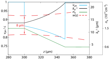
Figure 1 illustrates the scenario by plotting the longitudinal profile of the relevant parameters: electron density (green line), the corresponding (black), and (blue) at m behind the bunch driver center. The laser transverse width is also shown (using the axis scale, dashed line), with its focal plane located at , where also the downramp starts. This way the trapping facilitation effect is maximized for the majority of the released electrons. The plasma density ramp length fulfills the condition everywhere, to avoid density transition injection Suk et al. (2001), while the initial density decreases linearly to the final density . Experimental realization of such a downramp is possible taking into account that similarly sharp downramps have been experimentally demonstrated Schmid et al. (2010); Buck et al. (2013). At the co-moving laser pulse position behind the driver electrons, i.e. the birth place of He electrons, as increases from to , the phase velocity decreases to a minimum phase velocity of at the end of the ramp, then bounces back to when the flat top is reached.
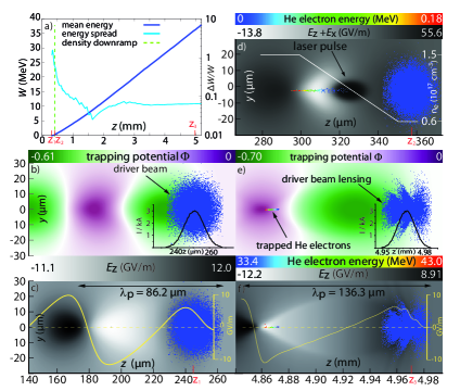
The addition of the described downramp enables trapping despite of the moderate drive beam current. PIC simulations show in figure 2 a), how the released He electrons are trapped and gain energy linearly in the co-propagating blowout, reaching after (left -axis) of acceleration, corresponding to a mean gradient of . The green dashed vertical line indicates the position of the downramp, and the positions to mark the situation before the downramp (figure 2 b) and c), on the downramp (figure 2 d) and after (figure 2 e) and f). The energy spread saturates at after of acceleration (right -axis), which is due to partial He electron loss as discussed below. Figure 2 b) shows the trapping potential around position just before the downramp, calculated by numerically integrating the longitudinal electrostatic wake potential from the electric field derived from the PIC simulations. The electron bunch drive beam is shown in a 2D projection of the drive beam macro-particles with a longitudinal line-out of the drive beam current, peaking at . A trapping potential of indicates that an electron released at rest at this position can be trapped in the blowout region Pak et al. (2010). Here, the minimum trapping potential is only for and for . Therefore, no trapping is expected without a downramp, which is confirmed by separate simulations with flat plasma density profiles (see figure 3 a). In figure 2 c), the longitudinal electric field corresponding to the potential is represented by a color plot and an on-axis line-out. The field maximum is . Figure 2 d) shows the underdense photocathode in action: As the laser pulse reaches its focus at it releases He electrons, which begin to gain energy. To visualize the laser pulse, which is polarized in the figure plane, the sum of the longitudinal and transverse fields is shown.
Experimentally, positioning the laser pulse focus at the start of the plasma density downramp is straightforward, as -level spatial adjustment is routinely achievable in state-of-the-art experiments. After the downramp and the reduction of H-plasma density, the plasma wavelength is , and figure 2 e) and f) show the trapping potential and the longitudinal -field, respectively, after of acceleration at this density level. The drive beam shows an increase in the normalized emittance from to and a strong signature of underdense plasma lensing and betatron oscillations with the betatron function defined as . While the longitudinal drive bunch current is unaffected (compare lineouts in 2 b) and e), these effects have a significant impact on the local drive bunch density and consequently also on . The increase of is an explanation for the slightly deeper trapping potential in figure 2 e) when compared to figure 2 b), despite the downramp which leads to a further decreased wave number-drive bunch length product away from its optimal value of . This advantageous effect is confirmed by separate simulation runs where the drive beam energy is set to a very high value to preclude plasma lensing and to increase the betatron length. In this case simply decreases from before the ramp to after the ramp, and both the worse and the decreased lead to reduced and reduced electric longitudinal field , compared to and in case of the plasma lensing and scalloping, as shown in snapshots 2 e) and f), respectively.
This analysis demonstrates vividly the effect of stalling the plasma wave phase velocity and the possibility of inducing trapping even in unoptimized underdense photocathode cases. At the same time, in the blowout cavity behind the driver bunch no LIT electrons are injected by downramp injection, and shallow trapping potentials suppress LIT electron trapping outside of the density downramp region. Both effects combined allow for a clean underdense photocathode process and ultrahigh witness beam quality, unspoiled by dark current.
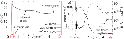
Figure 3 a) confirms that no trapping occurs when no downramp is present, based on simulation runs at high (, red plot) and low (, orange plot) densities, corresponding to the densities before and after the ramp. A total He electron charge of is generated, which is in very good agreement with a numero-analytical estimate of the charge yield based on Gaussian laser beam propagation and tunnel ionization. However, none of these electrons are trapped, but quickly slip out of the blowout and the co-propagating simulation box and are lost. In the DTH case (black plot), in contrast, most of the released charge is sufficiently accelerated due to the downramp, and while even in this case substantial charge is subsequently lost, eventually are fully trapped. Figure 3 b) shows the evolution of the witness bunch normalized emittance (left -axis, dashed line) and the corresponding brightness (right -axis, solid line). All electrons are counted, including those that are ultimately not trapped, which, in addition to mixing processes Xi et al. (2013); Xu et al. (2014), is responsible for the characteristic shape of the plots. The relatively sudden decrease of brightness and increase of emittance, respectively, at result from the last untrapped electrons leaving the simulation box as the simulation progresses. The final values are and , which is comparable to results from straightforward underdense photocathode simulations Xi et al. (2013). The final witness bunch length is somewhat increased compared to normal Trojan Horse because of plasma blowout lengthening, in this case to , leading to a peak witness current of . This bunch stretching in DTH and the effective suppression of dark current are advantages for FEL applications in the context of the radiation slippage, cooperation length and slice energy spread.
In summary, the analysis of the DTH scheme shows that the implementation of experimentally viable downramps, such as used in LWFA experiments, can dramatically increase the number of accelerator systems that qualify for implementing underdense photocathodes, for example aiming at driver-witness type emittance/brightness/luminosity transformer systems. Here, a complementary approach when compared to increasing the driver bunch current is used, namely shaping the plasma properties to stall the phase velocity to facilitate trapping. It is shown that trapping is possible already with driver currents of , thus reducing the otherwise required peak driver current by a factor of more than 2. This explicitly also makes this scheme accessible to double-hybrid schemes where the electron drive beam is generated via LWFA, as proposed for extending the energy gain in Hidding et al. (2010). Recent experiments indicate that LWFA accelerated electron bunches are able to drive a PWFA blowout Masson-Laborde et al. (2014). Such all-optical systems offer advantages of compactness, and an inherent optimal synchronization between the underdense photocathode laser and the electron bunch driver, and further for seeding in the context of FEL, for other light sources and for pump-probe type investigations in general.
Acknowledgements.
This work was supported by DFG, STFC 4070022104, DOE DE-SC0009533, DE-FG02-07ER46272, DE-FG03-92ER40693, by ONR N00014-06-1-0925 and Helmholtz VH-VI-503. We acknowledge the assistance of the VSim development team. This research used computational resources of the National Energy Research Scientific Computing Center, which is supported by DOE DE-AC02-05CH11231, and of JUROPA, and of HLRN. D.A.J. acknowledges support of the UK EPSRC (EP/J018171/1) and the EC’s 7th Framework Programme (LASERLAB-EUROPE no. 284464, EUCARD-2 project no. 312453) and the Extreme Light Infrastructure (ELI).References
- Akhiezer and Fainberg (2008) A. Akhiezer and Y. B. Fainberg, Ukr. J. Phys. 53 Special Issue, 87 (2008).
- Fainberg (1956) Y. B. Fainberg (AIP, Geneva, 1956) p. 84.
- Veksler (1956) V. Veksler (AIP, Geneva, 1956) p. 80.
- Budker (1956) G. Budker (AIP, Geneva, 1956) p. 68.
- Dawson (1959) J. M. Dawson, Phys. Rev. 113, 383 (1959).
- Akhiezer and Polovin (1956) A. I. Akhiezer and R. V. Polovin, JETP 3, 696 (1956).
- Esarey et al. (1996) E. Esarey, P. Sprangle, J. Krall, and A. Ting, IEEE Transactions on Plasma Science 24, 252 (1996).
- Blumenfeld et al. (2007) I. Blumenfeld et al., Nature 445, 741 (2007).
- Litos et al. (2014) M. Litos et al., Nature 515, 92 (2014).
- Hidding et al. (2011) B. Hidding et al., “Method for generating electron beams in a hybrid plasma accelerator,” (2011), german Patent DE 10 2011 104 858.1, US/PCT patent Ser. No. PCT/US12/043002.
- Hidding et al. (2012a) B. Hidding et al., Phys. Rev. Lett. 108, 035001 (2012a).
- Hidding et al. (2012b) B. Hidding et al., AIP Conference Proceedings 1507, 570 (2012b).
- Xi et al. (2013) Y. Xi et al., Phys. Rev. ST Accel. Beams 16, 031303 (2013).
- Li et al. (2013) F. Li et al., Phys. Rev. Lett. 111, 015003 (2013).
- Xu et al. (2014) X. L. Xu et al., Phys. Rev. Lett. 112, 035003 (2014).
- Chen et al. (1985) P. Chen et al., Phys. Rev. Lett. 54, 693 (1985).
- Rosenzweig et al. (1988) J. B. Rosenzweig et al., Phys. Rev. Lett. 61, 98 (1988).
- Tajima and Dawson (1979) T. Tajima and J. M. Dawson, Physical Review Letters 43, 267 (1979).
- Pukhov and Meyer-ter Vehn (2002) A. Pukhov and J. Meyer-ter Vehn, Applied Physics B-Lasers and Optics 74, 355 (2002).
- Kostyukov et al. (2009) I. Kostyukov et al., Phys. Rev. Lett. 103, 175003 (2009).
- Kirby et al. (2009) Kirby et al., Phys. Rev. ST Accel. Beams 12, 051302 (2009).
- Bulanov et al. (1998) S. Bulanov et al., Phys. Rev. E 58, R5257 (1998).
- Geddes et al. (2008) C. G. R. Geddes et al., Phys. Rev. Lett. 100, 215004 (2008).
- Schmid et al. (2010) K. Schmid et al., Phys. Rev. ST Accel. Beams 13, 091301 (2010).
- Gonsalves et al. (2011) Gonsalves et al., Nat Phys 7, (2011).
- Suk et al. (2001) H. Suk et al., Phys. Rev. Lett. 86, 1011 (2001).
- Wiggins et al. (2010) S. M. Wiggins et al., Plasma Physics and Controlled Fusion 52, 124032 (2010).
- Lundh et al. (2011) O. Lundh et al., Nat Phys 7, 219 (2011).
- Nieter and Cary (2004) C. Nieter and J. R. Cary, Journal of Computational Physics 196, 448 (2004).
- Umstadter et al. (1995) D. Umstadter, J.-K. Kim, and E. Dodd, “Method and apparatus for generating and accelerating ultrashort electron pulses,” (1995), US patent Ser. No. 5,789,876.
- Umstadter et al. (1996) D. Umstadter, J. K. Kim, and E. Dodd, Phys. Rev. Lett. 76, 2073 (1996).
- Chen et al. (2006) M. Chen et al., Journal of Applied Physics 99, 056109 (2006).
- Bruhwiler et al. (2003) D. L. Bruhwiler et al., Physics of Plasmas 10, 2022 (2003).
- Barov et al. (2004) N. Barov et al., Phys. Rev. ST Accel. Beams 7, 061301 (2004).
- Fubiani et al. (2006) G. Fubiani et al., Phys. Rev. E 73, 026402 (2006).
- Buck et al. (2013) A. Buck et al., Phys. Rev. Lett. 110, 185006 (2013).
- Pak et al. (2010) A. Pak et al., Phys. Rev. Lett. 104, 025003 (2010).
- Hidding et al. (2010) B. Hidding et al., Phys. Rev. Lett. 104, 195002 (2010).
- Masson-Laborde et al. (2014) P. E. Masson-Laborde et al., ArXiv e-prints (2014), arXiv:1408.2494 [physics.plasm-ph] .