Cosmic Ray Test of Mini-drift Thick Gas Electron Multiplier Chamber for Transition Radiation Detector
Abstract
A thick gas electron multiplier (THGEM) chamber with an effective readout area of 1010 cm2 and a 11.3 mm ionization gap has been tested along with two regular gas electron multiplier (GEM) chambers in a cosmic ray test system. The thick ionization gap makes the THGEM chamber a mini-drift chamber. This kind mini-drift THGEM chamber is proposed as part of a transition radiation detector (TRD) for identifying electrons at an Electron Ion Collider (EIC) experiment. Through this cosmic ray test, an efficiency larger than 94 and a spatial resolution 220 m are achieved for the THGEM chamber at -3.65 kV. Thanks to its outstanding spatial resolution and thick ionization gap, the THGEM chamber shows excellent track reconstruction capability. The gain uniformity and stability of the THGEM chamber are also presented.
keywords:
EIC, eSTAR, TRD, mini-drift THGEM, cosmic ray testPACS:
25.75.Cj, 29.40.Cs1 Introduction
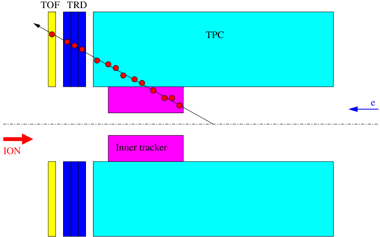
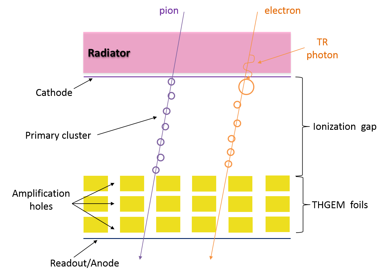
An Electron Ion Collider (EIC) is being considered as the next generation QCD facility to understand how the visible universe is built up [2]. More specifically, the EIC will probe with unprecedented precision the low Bjorken-x domain where gluons and sea quarks dominate for both nucleons and nuclei. A possible realization of the accelerator facility based on the (currently operating) Relativistic Heavy Ion Collider (RHIC), called eRHIC, has been proposed [3]. The Solenoidal Tracker at RHIC (STAR) detector, one of the two major experiments at RHIC, has been planned to evolve into eSTAR with a suite of upgrades optimized for the EIC physics program. The eSTAR detector performance and a broad range of flagship measurements, which have been identified as part of the EIC science case, have been studied through simulation. eSTAR has been found to be well suitable for an initial stage of eRHIC [4]. However, one of the major experimental challenges is to cleanly identify the scattered electron and to provide precise kinematics of the interaction. We have proposed a compact transition radiation detector (TRD) followed by an endcap time-of-flight (eTOF) detector with an additional converter [5]. Figure 1 illustrates a schematic view of the detector configuration relevant to this proposal. The low-material time projection chamber (TPC) (and a possible inner tracker) in a solenoidal field in front of TRD, provides tracking, momentum, and photon rejection. The combination of eTOF and TPC provides electron identification at electron momentum less than a few GeV/ [6]. Furthermore, eTOF provides hadron identification in the case that both hadrons and the scattered electrons strike the eTOF, as well as the collision time reference. The proposed TRD is similar to the ALICE TRD [7], providing measurement in addition to the transition radiation (TR) signal and tracklet reconstruction capability, but with a readout stage based on thick gas electron multiplier (THGEM) chamber rather than the multiple wire proportional chamber (MWPC). The operation principle and design of the THGEM based TRD chamber is depicted by Fig. 2. The TRD serves two functions. Firstly, it provides additional measurement with a Xe rich gas mixture at the entire momentum range. This is essential for small angle scattering, where only a small section of the particle trajectory falls within the tracking detector acceptance, resulting in few hits in the tracking detector and worse resolution (1/ rule). Through the simulation [5], TRD with 300 m spatial resolution is enough for tracking due to the thick TRD radiator and material in the TPC endcap. Secondly, it adds necessary TR signal to particles at high momentum. The TR threshold is around 10002000. From a practical standpoint, only electrons provide such radiation into the ionization chamber in the TRD, boosting the effective electron to even higher values from the existing relativistic rise.
Comparing with the gas electron multiplier (GEM) chamber first introduced in 1996 at CERN [8], the THGEM chamber is one of the most recently developed micropattern gas detectors [9]. The THGEM is a robust, high-gain gaseous electron multiplier, and has a hole-structure similar to the GEM [10]. It is manufactured economically by mechanically drilling sub-millimeter diameter holes in a thin printed-circuit board (PCB), followed by Cu-etching of the hole’s rim.
Due to lack of Xe in laboratory, we used the Ar mixture instead of Xe mixture as the working gas of the THGEM chamber. Some experiments were carried out for comparing the THGEM or GEM chamber performance in large variety of gases [11, 12, 13, 14]. The maximum gain measured with THGEM chamber operating in Xe is similar to that measured with THGEM chamber operating in Ar at atmospheric pressure [11]. Meanwhile, the maximum GEM chamber gains measured in Ar/CO2 and Xe/CO2 are comparable at atmospheric pressure [13]. Moreover, the results in [11] show the best energy resolution of the specified THGEM chamber reached in Ar with 5.9 keV x-rays is 30 FWHM while that reached in Xe is 27 FWHM. These previous experiment results illustrate the results measured with the THGEM chamber operating in Ar mixture are able to provide a valid reference for that operating in Xe mixture.
In this paper, we focus on THGEM chamber’s performance in various aspects such as detection efficiency, spatial resolution, gain uniformity and stability, especially the track reconstruction capability. The paper is organized as follows. Section 2 describes the THGEM chamber. The cosmic ray test system setup is presented in Section 3. Section 4 describes the performance of the THGEM chamber. Section 5 provides a concluding summary.
2 The THGEM chamber
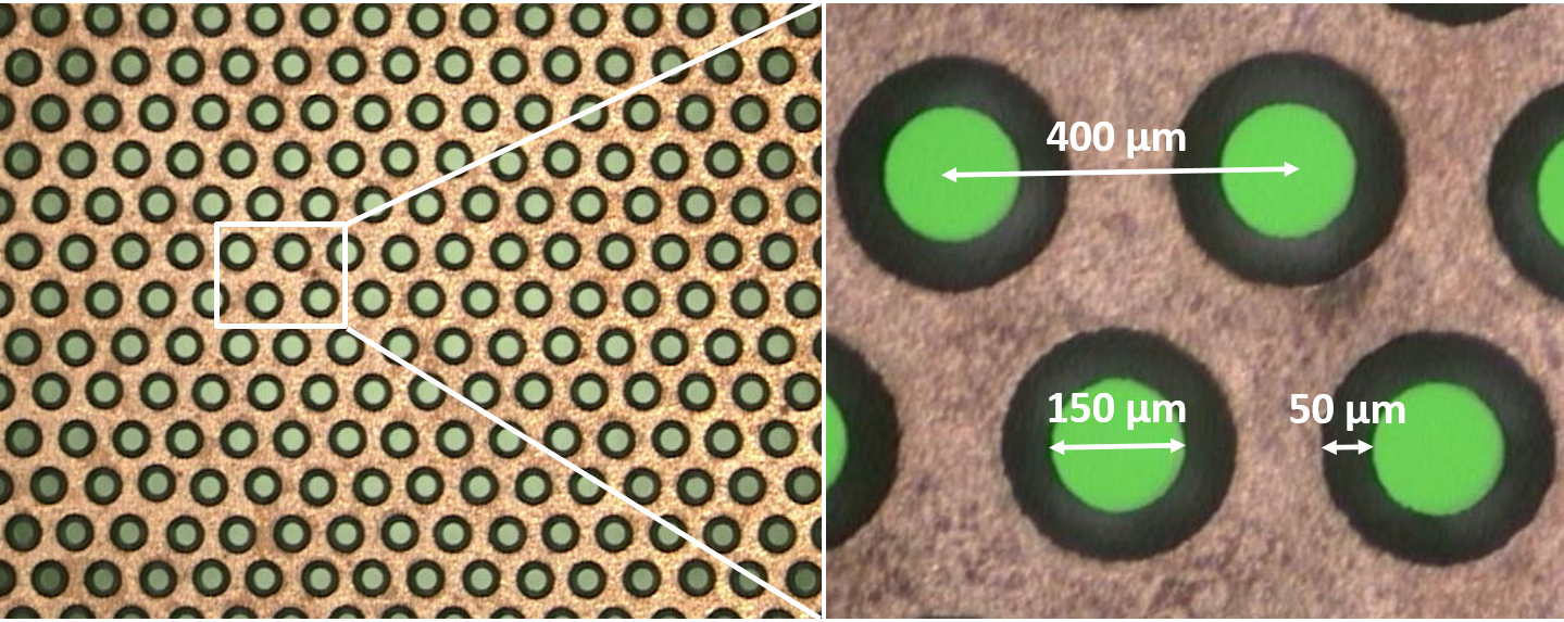
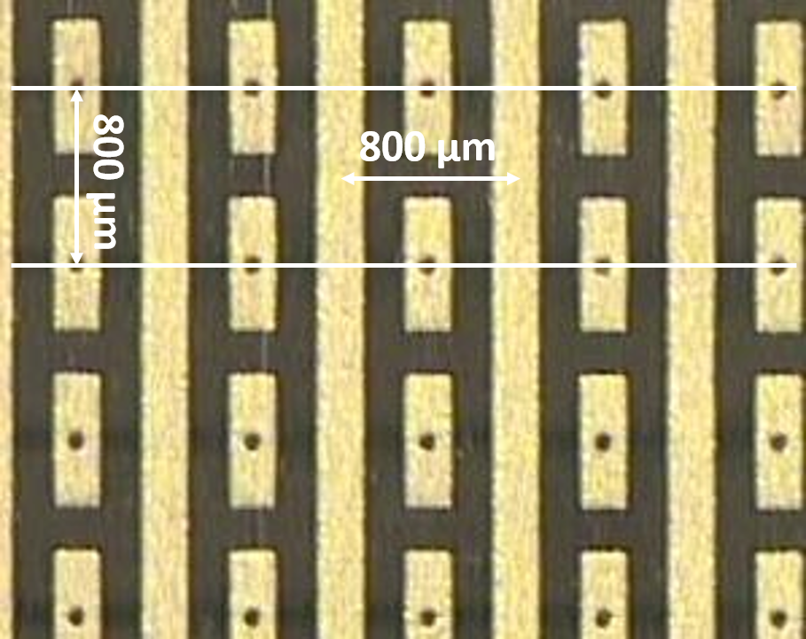
The THGEM chamber in this study uses three THGEM foils in cascade. These foils are provided by the Institute of High Energy Physics (IHEP), China. The foil structure is shown in Fig. 3. The major parameters include foil thickness 300 m, hole diameter 150 m, and hole pitch 400 m. The rim clearance region around the hole is 50 m. The effective readout area given by the foil is 1010 cm2. Figure 4 depicts the readout board structure of the THGEM chamber. The readout unit, with a pitch of 800 m, is strip-style in direction while pad-style (inter-connected beneath) in direction. The thickness of the THGEM chamber ionization gap is 11.3 mm. The THGEM chamber is placed in a gas-tight aluminum box with a gas mixture (90 Ar + 10 CO2) at atmospheric pressure.

3 Cosmic ray test system setup
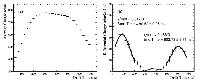
Two different setups of the cosmic ray test system are shown in Fig. 5. Three scintillators read out by photomultipliers, providing trigger for this system, are placed upstream and downstream of the three GEM chambers. The effective trigger area is around 1212 cm2. The system consists of two regular GEM chambers (GEM0, GEM2) and one THGEM chamber (GEM1) in between. The vertical ( direction) distance between the THGEM chamber and the regular GEM chamber is 10.5 cm. The readout boards of the two regular GEM chambers, with 3.8 mm ionization gap width, are identical to that of the THGEM chamber. These two GEM chambers are used to calibrate the THGEM chamber. They can also be used to measure the cosmic ray tracklet slope to study the track reconstruction capability of the THGEM chamber. The left setup in Fig. 5 with all the detectors aligned vertically is used to measure the detection efficiency of the THGEM chamber while the right setup with 4.1 cm horizontal offset between the THGEM chamber and the regular GEM chamber along direction is used to study other performance of the THGEM chamber, such as spatial resolution, track reconstruction capability, gain uniformity and stability. The front end electronics (FEE) of these three GEM chambers are all based on the APV25-S1 chip [15], and the readout system is almost the same as that of the forward GEM tracker (FGT) at the STAR experiment [16]. The only difference is that the front end card has only 2 APV chips rather than 5 used for the FGT. Each readout unit is sampled in 27 time bins (26.7 ns bin width) along electron drift direction ( direction). The typical average charge as a function of drift time for the mini-drift THGEM chamber at operating voltage measured by this readout system is shown in Fig. 6(a), and its width is the drift time in the ionization gap. The drift time in the ionization gap can be calculated through the differential spectrum of the average charge vs. drift time, shown in Fig. 6(b). Thus, the electron drift velocity can be derived and the value is 2.19 cm/s (1.13/(0.603-0.087) cm/s). Because we used 3 THGEM foils in cascade, the effective drift length should be a little larger than the ionization gap width. So the drift velocity measured by this method is a little smaller than the real velocity value.
4 The performance of the THGEM chamber
4.1 The efficiency plateau of the THGEM chamber
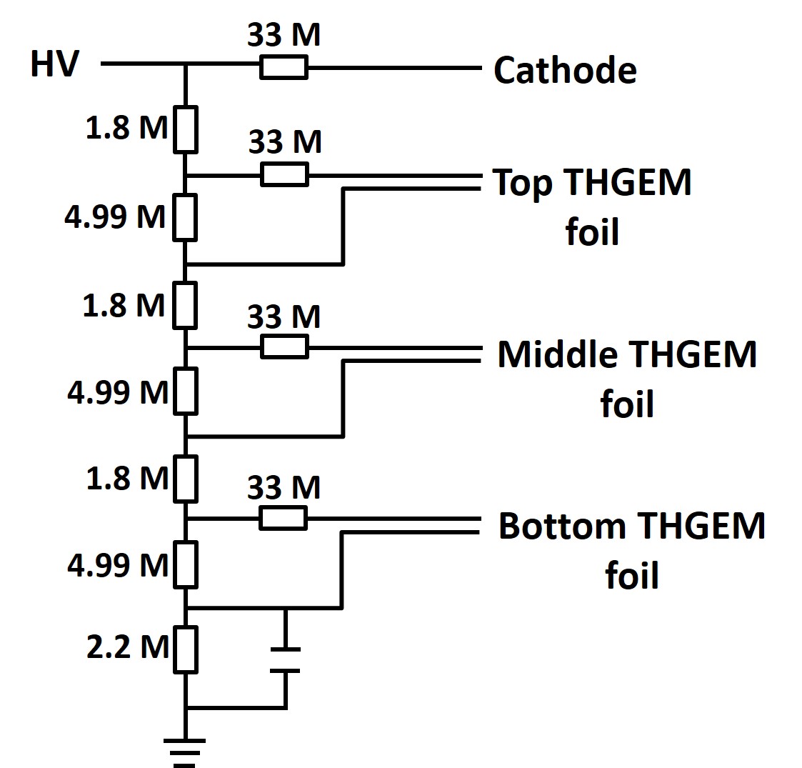
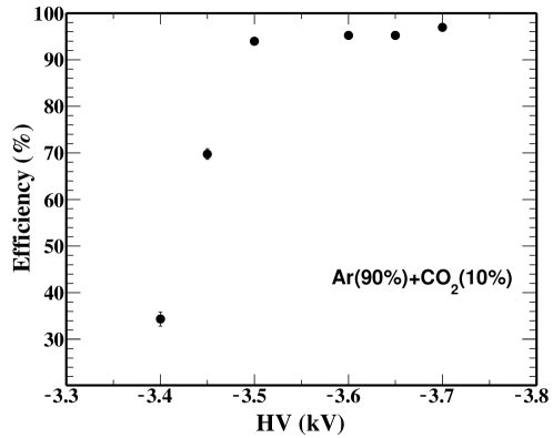
In order to find the optimum operating voltage of the THGEM chamber, the detection efficiency is scanned as a function of HV with the cosmic ray test system. A schematic view of the THGEM chamber HV divider is shown in Fig. 7. The efficiency plateau of the THGEM chamber is shown in Fig. 8. The detection efficiency goes above 90 when the applied HV is higher than -3.5 kV. -3.65 kV is selected as the operating HV for the THGEM chamber at which the efficiency is greater than 94.
4.2 The spatial resolution of the THGEM chamber
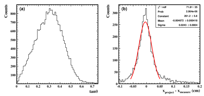
The two regular GEM chambers’ performance was tested elsewhere before this cosmic ray test. Their spatial resolutions are found to be better than 150 m [17]. The zenith angle () distribution of cosmic ray recorded by this system is shown in Fig. 9(a). The zenith angle is calculated by the cosmic ray hit positions on the two regular GEM chambers using the following expression tan, where , are the , positions measured by GEM0 using the center of gravity method while , are provided by GEM2. , are the positions of GEM0 and GEM2 along direction. The vertically incident cosmic ray tracks are selected (tan 0.1) to measure the spatial resolution of the THGEM chamber. Figure 9(b) shows the residual distribution in the direction, , where is the cosmic ray trajectory position at the THGEM chamber projected from the two regular GEM chambers and is the hit position measured by the THGEM chamber. The residual distribution in direction is very similar. The 1-D spatial resolution of the THGEM chamber is 220 m after subtracting the contribution from the two regular GEM chambers.
4.3 Electron drift velocity measured by the THGEM chamber
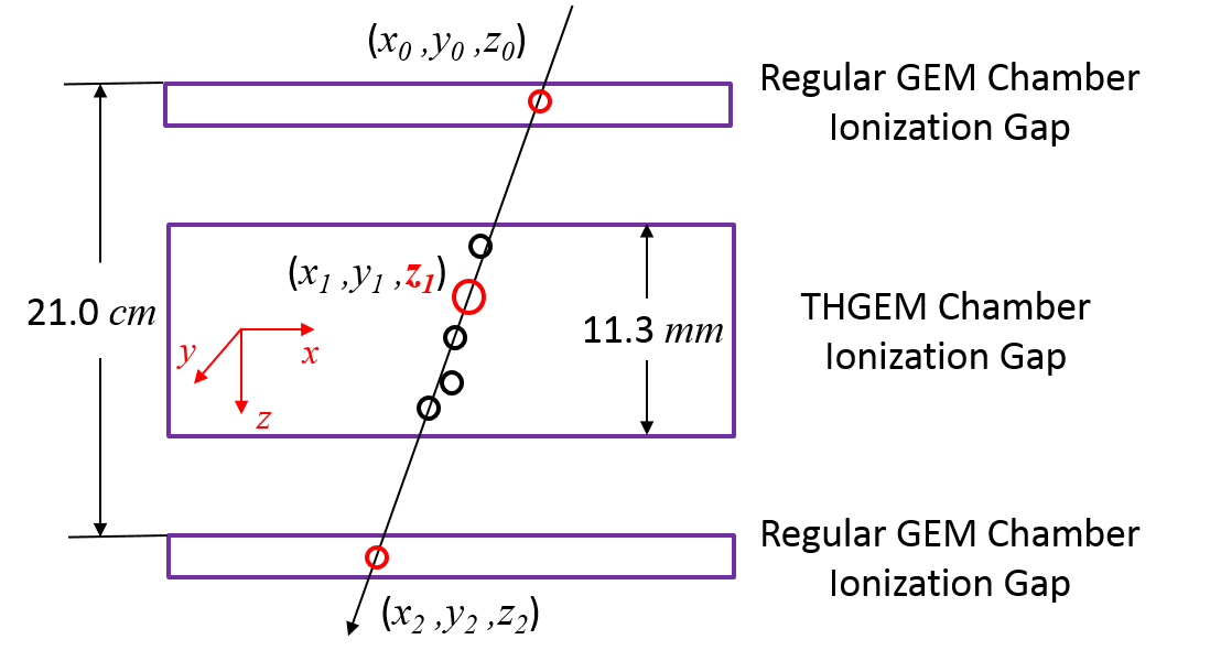
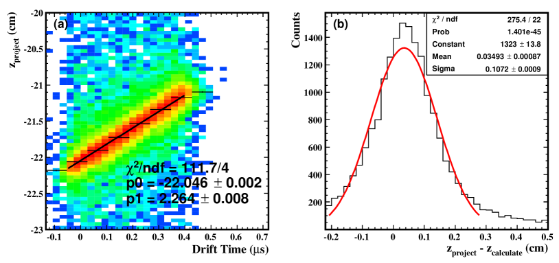
The electron drift velocity in the gas mixture can be obtained through correlating the hit point’s position with its corresponding drift time in the THGEM chamber. The hit point with maximum energy deposit of a large zenith angle track is selected firstly. The , positions (, ) of this point are calculated by the center of gravity method. The position () of this point is then derived through the equation , where , , , , , have been defined in the previous section. This process is depicted in Fig. 10. The correlation between position and its corresponding drift time is shown in Fig. 11(a). The electron drift velocity can then be extracted from a linear fit to the correlation. The electron drift velocity (at drift E 0.26 kV/cm) obtained using this method is 2.26 cm/s, consistent with the data commonly used in the literature [18]. The spatial resolution of the THGEM chamber in direction can be derived by plotting the difference of position projected by two regular GEM chambers and the position calculated from the drift velocity and drift time. The overall spatial resolution in direction is 1.1 mm, as Fig. 11(b) depicts, including the uncertainty from the trigger clock distribution (TCD) (0.2 mm) and the uncertainty from the THGEM and the regular GEM chamber spatial resolutions in , direction (0.8 mm, , this formula is derived under the assumption that the THGEM (GEM) chamber has the same spatial resolution in , direction. = 0.15 mm is the regular GEM chamber spatial resolution in direction while = 0.22 mm is the THGEM chamber spatial resolution in direction, and tan = 0.32 is the average value from Fig. 9(a)). With these contributions subtracted, the intrinsic spatial resolution in direction of the THGEM chamber is 0.7 mm.
4.4 Track reconstruction capability of the THGEM chamber
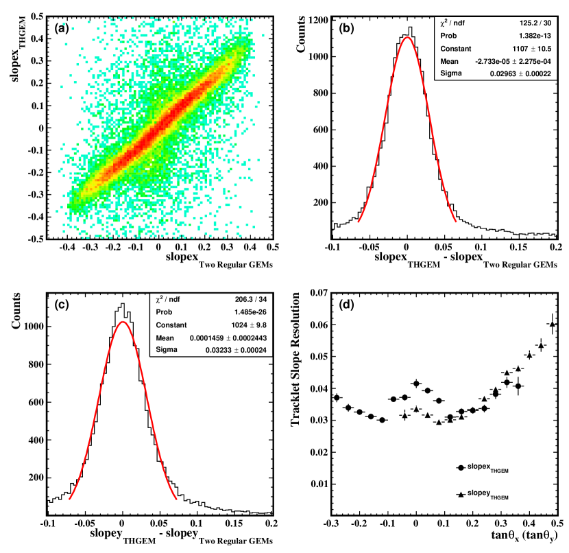
The cosmic ray can be reconstructed just by the THGEM chamber. Firstly, searching for a hit point for each time bucket. If found, the , positions of this point are calculated using the center of gravity method. Secondly, all these hit points are fitted by a linear function to obtain the cosmic ray tracklet slope (tan) if the number of points is more than two. Thus, the correlation between (measured by the THGEM chamber itself) and (the slope of the same cosmic ray track measured by the two regular GEM chambers) can be used to study the tracklet slope resolution of the THGEM chamber, which characterizes the track reconstruction capability. The resolution of tracklet slope obtained by the two regular GEM chambers is since the distance between the two regular GEMs along direction is 21.0 cm and the regular GEM’s spatial resolution in or direction is 150 m. Figure 12 shows the correlation between tracklet slope measured by the THGEM chamber and that measured by the two regular GEM chambers in direction, the tracklet slope resolution of the THGEM chamber in and direction and the THGEM chamber tracklet slope resolution as a function of cosmic ray incident angle. The tracklet slope resolution in () direction is 0.03. Moreover, the results shown in Fig. 12(d) indicate that the tracklet slope resolution deteriorates with increasing incident angle as previously observed in similar studies [19].
4.5 Gain uniformity and stability of the THGEM chamber
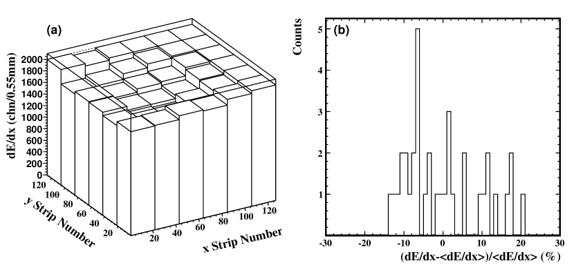
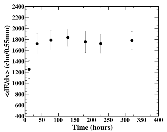
The readout board of the THGEM chamber is artificially divided into 66 identical sub-regions. The non-uniformity is described using , where is the average recorded charge for all tracks passing the given region while is the average of over all regions. The measured of different sub-regions is shown in Fig. 13(a). The non-uniformity for most of the sub-regions (32 out of 36) is less than 15 as Fig. 13(b) depicts. The as a function of operating time for the THGEM can be found in Fig. 14. The THGEM shows an increase of gain in the first 24 hours and remains stable afterwards.
5 Conclusions
A mini-drift THGEM chamber has been tested in laboratory using cosmic rays. The results of the cosmic ray test reveal the excellent performance of the THGEM chamber. The detection efficiency of the THGEM chamber is greater than 94 and the 1-D spatial resolution is 220 m. Moreover, the THGEM chamber shows good spatial resolution (0.7 mm) along electron drift direction and good tracklet slope resolution (0.03) in , direction, which are important for the small incident angle track reconstruction. In addition to these, the THGEM chamber shows good uniformity and stability during a long run. Such work offers an important reference for the proposed TRD design.
6 Acknowledgments
This work was supported in part by (BNL EIC RD funding) the Nuclear Physics Division within the U.S. DOE Office of Science. This work is supported in part by the National Natural Science Foundation of China under Grant nos. 11375180, 11275196. We express our gratitude to the STAR Collaboration and the RHIC Computing Facility at Brookhaven National Laboratory for their support.
References
- [1]
- [2] A. Accardi et al. arXiv:1212.1701 (2012)
- [3] E.C. Aschenauer et al. arXiv:1409.1633 (2014)
-
[4]
The STAR Collaboration,
https://drupal.star.bnl.gov/STAR/files/eSTAR-LoIv300.pdf. -
[5]
STAR Transition Radiation Detector Proposal:
https://wiki.bnl.gov/conferences/images/3/3d/TRDEICRDproposalFY2012v3.pdf. - [6] M. Shao et al., Nucl. Instr. Meth. A 558, (2006) 419
- [7] ALICE Transition Radiation Detector Proposal: CERN/LHCC 99-13, LHCC/P3-Addendum 2, 7 May 1999.
- [8] F. Sauli, Nucl. Instr. Meth. A 386, (1997) 531.
- [9] R. Chechik et al., Nucl. Instr. Meth. A 535, (2004) 303.
- [10] A. Breskin et al., Nucl. Instr. Meth. A 598, (2009) 107.
- [11] R. Alon et al., 2008 JINST 3 P01005.
- [12] J. Miyamoto et al., 2010 JINST 5 P05008
- [13] A. Bondar et al., Nucl. Instr. Meth. A 419, (1998) 418.
- [14] A. Bondar et al., Nucl. Instr. Meth. A 481, (2002) 200.
- [15] M.J. French et al., Nucl. Instr. Meth. A 466, (2001) 359.
- [16] G.J. Visser et al., Real Time Conference (RT), 18th IEEE-NPSS, (2012) p1-6.
-
[17]
S. Das, RHIC AGS Annual User’s Meeting, 2013.
https://drupal.star.bnl.gov/STAR/files/gmtposterrhicags21stJunev20.pdf - [18] T. Zhao et al., Nucl. Instr. Meth. A 340, (1994) 485.
- [19] F. Simon et al., Nucl. Instr. Meth. A 598, (2009) 432.