Spontaneous formation of kagome network and Dirac half-semimetal on a triangular lattice
Abstract
In spin-charge coupled systems, geometrical frustration of underlying lattice structures can give rise to nontrivial magnetic orders and electronic states. Here we explore such a possibility in the Kondo lattice model with classical localized spins on a triangular lattice by using a variational calculation and simulated annealing. We find that the system exhibits a four-sublattice collinear ferrimagnetic phase at 5/8 filling for a large Hund’s-rule coupling. In this state, the system spontaneously differentiates into the up-spin kagome network and the isolated down-spin sites, which we call the kagome network formation. In the kagome network state, the system becomes Dirac half-semimetallic: The electronic structure shows a massless Dirac node at the Fermi level, and the Dirac electrons are almost fully spin polarized due to the large Hund’s-rule coupling. We also study the effect of off-site Coulomb repulsion in the kagome network phase where the system is effectively regarded as a 1/3-filling spinless fermion system on the kagome lattice. We find that, at the level of the mean-field approximation, a -type charge order occurs in the kagome network state, implying the possibility of fractional charge excitations in this triangular lattice system. Moreover, we demonstrate that the kagome network formation with fully-polarized Dirac electrons are controllable by an external magnetic field.
pacs:
71.10.Fd, 71.27.+a, 72.25.DcI Introduction
The ferromagnetic (FM) Kondo lattice model, often called the double-exchange (DE) model Zener1951 ; Anderson1955 ; de-Gennes_1960 , is one of the fundamental models for correlated electron systems. It has been extensively studied for a long time, mainly for understanding of the physical properties of perovskite manganese oxides Kaplan1999 ; Tokura1999 . The phase transition to the FM metallic state by decreasing temperature and the colossal negative magnetoresistance are well explained by the DE mechanism: An effective FM interaction is induced by the kinetic motion of electrons under the influence of the large Hund’s-rule coupling to localized magnetic moments. On the other hand, the competition between the FM DE interaction and the antiferromagnetic (AFM) superexchange (SE) interaction between the localized spins has also been studied intensively. In the early stage, a spin canting state with a spin-flop type ordering was predicted in the lightly doped region, which smoothly connects the AFM insulating state at half filling and a hole-doped FM metal de-Gennes_1960 . Later, the scenario was revisited; a phase separation (PS) was found to take place between the AFM insulator and FM metal, and hinders the canting state Yunoki_1998 ; Dagotto_2001 . In addition, at the commensurate 1/4 filling, the magnetic competition leads to the first-order transition from the FM metal to an insulator with a peculiar “flux”-type magnetic ordering Yamanaka1998 ; Agterberg2000 .
Recently, the FM Kondo lattice model has attracted renewed interest from the viewpoint of geometrical frustration in underlying lattice structures. In general, the geometrical frustration leads to competition between different magnetic orders, resulting in peculiar states, such as a complicated ordering, liquid-like, and glassy states. Such peculiar magnetism significantly affects the electronic state of itinerant electrons and gives rise to peculiar transport phenomena. A typical example is the unconventional anomalous (or topological) Hall effect discovered in some pyrochlore oxides Taguchi2001 ; Nakatsuji2006 ; Machida2007 . Theoretically, the topological Hall effect is caused by the coupling of itinerant electrons to a noncoplanar spin configuration with nonzero spin scalar chirality Loss1992 ; Ye1999 ; Tatara2002 . Indeed, such a mechanism was investigated in many frustrated systems, such as triangular Martin2008 ; Akagi2010 ; Kato2010 , kagome Ohgushi2000 ; Mathieu2006 ; Ishizuka2013a ; Rahmani2013 ; Barros2014 , face-centered-cubic Shindou2001 , and pyrochlore lattices Udagawa2013 . Fermi surface properties are important for stabilizing such noncoplanar orders Akagi2012 ; Hayami2014_FS . Other interesting phenomena are resistivity minimum Nakatsuji2006 ; Sakata2011 and bad-metallic behavior Iguchi2009 ; Iguchi2011 . These peculiar transport properties were also discussed theoretically Udagawa2012 ; Chern2013 ; Motome2010a ; Kumar2010 .
The competition between the FM DE interaction and the AFM SE interaction has also been studied in geometrically frustrated systems. For instance, a variety of magnetic phases were predicted by the mean-field analysis in kagome and pyrochlore lattice systems Ikoma2003 . Monte Carlo studies were done for a pyrochlore lattice system, unveiled bad-metallic behavior Motome2010a , a peculiar PS Motome2010b , and a spontaneous spin Hall effect by inversion symmetry breaking Ishizuka2013b . Triangular and checkerboard lattice systems were also studied by Monte Carlo simulation, and scalar chiral ordered phases were found Kumar2010 ; Venderbos2012 . Furthermore, the low density region in the triangular lattice system was studied by variational calculations, and a noncoplanar three-sublattice spin canting order was found adjacent to a PS Akagi2011 . These results indicate that the competition between the FM DE and AFM SE interactions leads to much richer physics in geometrically frustrated systems.
In this paper, we investigate magnetic and electronic phases induced by the competition between the FM DE and AFM SE interactions on a triangular lattice. We study the ground state of the FM Kondo lattice model with the AFM SE interaction by complementarily using the variational calculation and the simulated annealing. We find that a four-sublattice collinear ferrimagnetic phase appears in the large Hund’s-rule coupling region at a commensurate 5/8 filling. In this phase, the triangular lattice system is spontaneously differentiated into a kagome network (KN) composed of up-spin sites and isolated down-spin sites. Under the KN formation, the electronic structure shows a Dirac node with linear dispersion, and the Fermi level at 5/8 filling is located just at the Dirac node. The Dirac electrons are almost fully spin polarized by the large Hund’s-rule coupling. A similar Dirac half-semimetal was also found at 1/3 filling in a different ferrimagnetic phase in the absence of the AFM SE interaction Ishizuka2012 . In our KN state, however, excess electrons over half filling are effectively regarded as spinless fermions on the kagome lattice at 1/3 filling. This leads us to study the effect of the off-site Coulomb repulsive interaction between itinerant electrons in the KN phase from the interest of a fractional charge excitation on a triangular lattice. We also clarify the effect of an external magnetic field on the KN formation with half-semimetallic Dirac electrons.
The organization of this paper is as follows. In Sec. II, we introduce the model and theoretical methods used in this paper. After introducing the FM Kondo lattice model in Sec. II.1, we describe the details of the variational calculation and simulated annealing in Secs. II.2 and II.3, respectively. In Sec. III, we present the results for the KN phase. We discuss the ground-state phase diagram obtained by the variational calculation (Sec. III.1), the electronic structure in the KN phase (Sec. III.2), and the stability of the KN phase examined by the simulated annealing (Sec. III.3). In Sec. III.4, we present the mean-field results for the effect of the electron-electron interaction between nearest-neighbor sites and discuss the possibility of fractional charge excitations. Moreover, we discuss a controllability of the Dirac half-semimetal, magnetic supersolid, and fractional charge excitations by an external magnetic field in Sec. III.5. Finally, Sec. IV is devoted to a summary. In the Appendix A, we present the results of variational calculations for the effect of single-ion anisotropy on the KN phase.
II Model and Method
In this section, we introduce the model and methods. The model is given in Sec. II.1. Details of the variational calculation and the simulated annealing are described in Secs. II.2 and II.3, respectively.
II.1 Kondo lattice model
We consider a Kondo lattice model on a triangular lattice, whose Hamiltonian is given by
| (1) |
The first term describes the hopping of itinerant electrons, () is a creation (annihilation) operator for an itinerant electron with spin on site i, and is the transfer integral. The sum is taken over the nearest-neighbor sites on the triangular lattice. The second term denotes the FM Hund’s-rule coupling between itinerant electron spins and localized spins, is the coupling constant, are Pauli matrices, and is a localized spin on site i. The last term describes the AFM SE interaction with the coupling constant between the nearest-neighbor localized spins (). Here, we consider classical spins for with . Note that the sign of is irrelevant unless localized spins are quantum ones. Hereafter, we take as the unit of energy, the lattice constant , and the Boltzmann constant .
II.2 Variational calculation
In the present study, we are interested in the ground-state (zero-temperature) phase diagram of the model in Eq. (1) in the parameter space of the electron filling (N is the total number of sites), , and [see Figs. 1(a) and 1(b)]. In order to obtain the global structure of the phase diagram, we adopted a variational method in which we compare the ground state energies of possible ordered states. The method is the same as those used in the previous studies Akagi2010 ; Akagi2011 , but we describe the details below for making the paper self-contained. The method is just used for readily searching parameter regions where possible interesting phases emerge. As a complementary method, we adopt the simulated annealing (Sec. II.3) to check the stability of the remarkable state that we are particularly interested in, the KN state (4e) in Fig. 1(c).
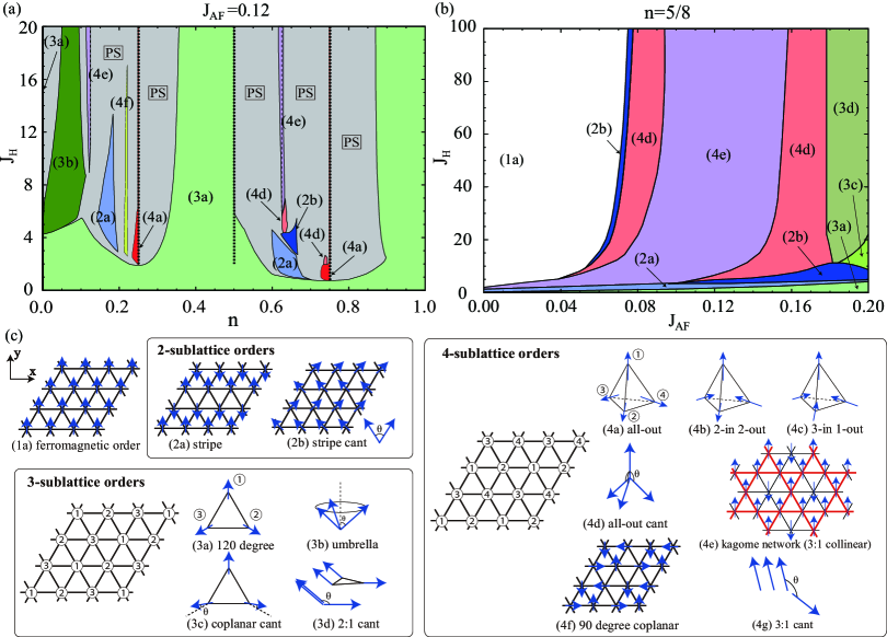
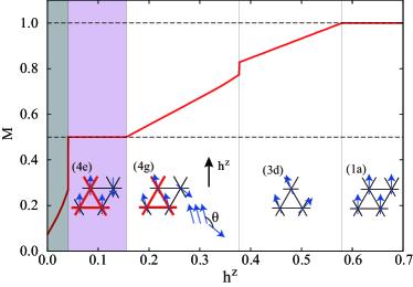
For the current model on the triangular lattice, we consider 14 different types of ordered states up to four-site unit cell, as shown in Fig. 1(c). Figure 1(c)(1a) shows a FM order. Figures 1(c)(2a) and 1(c)(2b) show two-sublattice orders: (2a) a collinear stripe order and (2b) a stripe order with a canting angle . Figures 1(c)(3a)-1(c)(3d) show three-sublattice orders: (3a) a noncollinear order, (3b) a noncoplanar umbrella-type order with angle (canted in the normal direction to the coplanar plane from the order) which was discussed in Ref. Akagi2011 , (3c) a coplanar order with canting angle for two spins from order, and (3d) a 2:1-type order with two parallel spins that have angle to the remaining one. Figures 1(c)(4a)-1(c)(4g) show four-sublattice orders: (4a) an all-out-type order which was discussed in detail in Ref. Akagi2010 and Akagi2012 , (4b) a two-in two-out-type order, (4c) a three-in one-out-type order, (4d) an all-out-type order with canting angle for three spins, (4e) a 3:1 collinear order, (4f) a coplanar order with a flux-type configuration, and (4g) a 3:1 canted order which is a four-sublattice version of the (3d) phase.
Among the various ordered states, we are particularly interested in the four-sublattice ferrimagnetic order (4e) in this paper. The magnetic ordering structure is collinear with three-up one-down spin configuration per four sites; the up-spin sites comprise a kagome lattice in the triangular lattice, and the down-spin sites are at the centers of the six-site hexagons in the up-spin kagome network, as shown in Fig. 1(c)(4e). We call this state (4e) the kagome network (KN) phase hereafter.
In the calculation of the energy for each state at zero temperature, we computed the integral over the first Brillouin zone by approximating it by the sum over grid points of . We carefully checked the possibility of electronic PS by comparing the grand potential as a function of the chemical potential Akagi2010 . In general, in the spin-charge coupled systems like the present model in Eq. (1), PS takes place between different magnetic phases, as the electron density jumps at the transition Yunoki_1998 ; Dagotto_2001 . Thus, two phases located on each side of PS coexist in the PS region, e.g., the (3a) and (4a) phases exist together in the PS region for at . For the states (2b), (3b), (3c), (3d), (4d), and (4g), we optimized the canting angle . Note that (2b) with , (3b) with , (3c) with , (4d) with , , , and (4g) with are equivalent to (2a), (3a), (3a), (4a), (4c), (4e), and (4e), respectively. Although an incommensurate order might take place for a general filling, we consider only uniform orders with the magnetic unit cells listed above.
II.3 Simulated annealing
In order to check the stability of the KN state (4e) against other ordered states having larger unit cells, we used the simulated annealing method. The simulated annealing is a technique for the optimization of a given function in the large parameter space Kirkpatrick1983 . It is often used to obtain a candidate for the ground state in complicated systems. In the present case, we considered an enlarged magnetic unit cell including 12 sites (see the inset of Fig. 3), and optimized the localized spin configuration by the simulated annealing. Namely, temperature is decreased gradually, and at each , the spin configuration is updated by the Monte Carlo sampling. The cooling process is done in the geometrical way, i.e., (), where is the temperature in the -th step. For instance, we take , the initial temperature , and for the final step of cooling in the calculations (the final temperature is ) in Secs. III.3 and III.5.
In the Monte Carlo sampling at each , we adopted the standard technique used for the model in Eq. (1) Yunoki_1998 . The partition function of the present system is given by , where and are traces over classical localized spin degrees of freedom and fermion degrees of freedom, respectively. Here, is the inverse temperature, is the chemical potential, and is the total number operator for fermions. In the Monte Carlo simulation, is calculated by using the Markov-chain Monte Carlo sampling. The updates are done by the single-spin flip on the basis of the standard Metropolis algorithm. In order to obtain the Monte Carlo weight, the trace is calculated by the exact diagonalization of the Hamiltonian for a given spin configuration. In the calculation, we took the summation over grid points of in the (folded) first Brillouin zone, which means that the effective system size is . It is crucial to take such a large system size in the calculations for the KN phase; since the KN phase has a Dirac node at the Fermi level as discussed in Sec. III.2, sufficiently dense grid points in the momentum space are necessary to take into account the energy contribution from the low-energy linear dispersion.
III Results and Discussions
In this section, we present the results obtained by the variational calculation and the simulated annealing introduced in Secs. II.2 and II.3, respectively. We first present the phase diagrams obtained by the variational calculation in Sec. III.1. We show that the system exhibits the KN phase at 5/8 filling. In Sec. III.2, we discuss the characteristic electronic structure of the KN phase, the massless Dirac node. Next, we discuss the stability of the KN phase by the simulated annealing in Sec. III.3. In Sec. III.4, we consider the effect of the electron-electron interaction between nearest-neighbor sites, , at the level of mean-field approximation. We present the phase diagram as a function of and , and discuss the robustness of the KN phase and the possibility of fractional charge excitations. Finally, we discuss the effect of an external magnetic field on the KN state by using the simulated annealing in Sec. III.5. We show that the system exhibits a continuous transition between the KN state and a magnetic supersolid.
III.1 Phase diagram by the variational calculation
Figure 1(a) shows the result of the ground-state phase diagram as a function of the electron filling and the Hund’s-rule coupling at . As the AFM SE interaction favors the Néel order on the triangular lattice, the (3a) state appears in a broad parameter region as shown in the figure. The phase diagram shares many aspects with the previous results in Refs. Akagi2010 and Akagi2011 : for instance, (4a) all-out chiral phases at and , and (3b) umbrella-type ordered phase in the low density region.
The new finding, however, is the KN state (4e) emerging at and . As described in Sec. II.2, the magnetic structure consists of the up-spin kagome network in the triangle lattice and the down-spins at the remaining sites, as shown in Fig. 1(c)(4e). To further confirm the stability of the KN phase within the variational calculation, we consider all the possible magnetic orders in a larger 12-site unit cell (see the inset of Fig. 3) by replacing the localized spins by the Ising spins. Namely, near the parameter regions in which the KN phase is found in Fig. 1(a), we enumerate the energies for states (including the equivalent states from the symmetry point of view) and compare them to find the lowest energy state. This procedure corresponds to the full parameter search within the 12-sublattice collinear spin configurations. We find that the KN state is the lowest energy state at and around , while it is not at and around . The result suggests that the (4e) phase near is taken over by another ordered state with a larger unit cell, but that at and around 5/8 filling is stable, at least, up to the 12-site unit cell in the Ising limit. The stability of the 5/8-filling phase will be further confirmed by the simulated annealing in the Heisenberg case in Sec. III.3. For these reasons, we consider only the 5/8-filling KN state hereafter.
As shown in Fig. 1(a), the (4e) KN state is not limited just at but appears in a narrow filling region around 5/8 filling (see also Fig. 6 in the Appendix A). This is related to the peculiar electronic structure of this state, as discussed in Sec. III.2. At , however, the KN phase is stabilized in a wide region of the parameter space of and . Figure 1(b) shows the ground-state phase diagram at as a function of and . As shown in the figure, the KN phase (4e) widely extends to the large region for an intermediate value of .
We note that the (4d) phases appear adjacent to the (4e) KN phase, as shown in Fig. 1(b). The (4d) state is a spin-canted version of (4e), as shown in Fig. 1(c) [(4d) with corresponds to (4e)]. The (4d) phase is interesting because the canted spins give a nonzero spin scalar chirality, leading to the topological Hall effect. The possibility of this chiral state was discussed also for the model defined on triangular-kagome lattices Akagi2013 .
Let us remark on the validity of the phase diagrams. Since the phase diagrams are obtained by the variational calculation while assuming a set of the variational states listed in Fig. 1(c), the results might include artificial phases. This should be carefully examined, in particular, in metallic regions where an incommensurate magnetic order with a longer period is anticipated [the ferromagnetic (1a) state is rather safe because of the robust DE mechanism]. However, the insulating phases are relatively trustworthy, as they are stabilized by opening an energy gap under the commensurate magnetic order. For instance, the (4a) states at and were confirmed by several unbiased numerical simulations Kumar2010 ; Kato2010 ; Barros2013 . The argument may be applied to the (4e) KN state that we are particularly interested in, because it is a semimetallic state with vanishing density of states accompanied by the commensurate magnetic order, as discussed in Sec. III.2. Indeed, in addition to the enumeration of all the possible Ising states in the 12-site unit cell discussed above, we will confirm the stability by the simulated annealing in Sec. III.3.
III.2 Dirac electrons in the kagome network phase
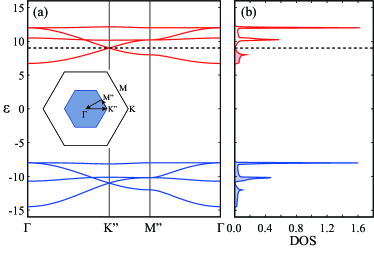
The KN phase found at has a peculiar electronic structure at the Fermi level: The Dirac node with linear dispersion. In other words, the system is a Dirac semimetal in the KN phase. This is understood as follows. First, let us discuss the limit of . In this limit, the hopping amplitude between up- and down-spin sites becomes zero: The up-spin KN and the isolated down-spin sites are completely separated. Consequently, the electronic structure consists of two independent contributions from them. The isolated down-spin sites give rise to a flat band at . Meanwhile, the up-spin KN leads to two copies of the band structure, each of which has the same form as that for the non-interacting tight-binding model on the kagome lattice. The band structure consists of two dispersive bands in the energy range of , in addition to a flat band at . Each pair of the two dispersive bands comprises a Dirac node at at the point in the Brillouin zone. At , the lower four bands (two dispersive and two flat bands) are fully occupied, while the upper bands are occupied only up to the Dirac point; hence, the Fermi level is located at the Dirac node in the upper two dispersive bands.
A similar situation is seen in the KN phase for finite but much larger than the noninteracting bandwidth. Figure 2 shows the electronic structure in the KN state at (note that does not change the electronic structure up to a constant energy shift). As shown in the figure, the electronic structure splits into two sets of bands: The upper (lower) set of bands centered at (). Each set of bands consists of two parts: One is similar to the kagome lattice electronic structure with the Dirac node at , and the other is a nearly flat mode at , as expected from the above consideration in the limit of . Although the form of each band is modified because of nonzero hopping between up- and down-spin sites allowed for finite , the Dirac node with linear dispersion is preserved and the Fermi level is just at the Dirac node, as shown in Fig. 2 comment1 .
The interesting point of the Dirac node is that the Dirac electrons are almost perfectly spin-polarized, e.g., over of the full moment at (fully polarized in the limit of ). Namely, this KN state provides a half-semimetal with Dirac electrons. The Dirac semimetal has been extensively studied from the discovery of graphene, from the potential for applications to electronic devices Neto2009 . In addition, the half-metallicity will also be beneficial for spintronics, as the electronic state can be manipulated by an external magnetic field. In Sec. III.5, we will demonstrate such magnetic field control. We note that a similar Dirac half-semimetal was discussed for a three-sublattice ferrimagnetic state at 1/3 filling Ishizuka2012 .
Now, let us discuss the stabilization mechanism of the KN phase at filling. The KN phase is a zero-gap semiconductor with the Dirac node at filling, as shown above. In many cases, a magnetically ordered phase is stabilized by opening an energy gap. Indeed, in the phase diagram in Fig. 1(a), the (4a) scalar chiral phases at 1/4 and 3/4 filling appear with opening an energy gap. The Dirac node is not a full gap, but it may give rise to an energy gain for the KN phase. The difference between the full-gap insulator and zero-gap semiconductor is seen in the phase diagram; the gapped chiral phases are limited just at 1/4 and 3/4 filling in the large region, as shown in Fig. 1(a) (see also Fig. 3 in Ref. Akagi2010 ), whereas the zero-gap semiconducting KN phase appears in a very narrow but a finite range of the electron filling around [see Fig. 1(a); see also Fig. 6 in the Appendix A]. The narrow but nonzero width in might be a footprint of the fact that the Dirac node formation contributes to the stabilization of the KN phase.
III.3 Stability of the kagome network phase: Simulated annealing results
Next, we examine the stability of the KN phase at 5/8 filling within the parameter space where the phase emerges in Fig. 1(b) by the simulated annealing for the enlarged 12-sites magnetic unit cell, as described in Sec. II.3. We find that it is difficult to obtain a converged result at 5/8 filling, suggesting (quasi)degeneracy with other states or the possibility of a larger sublattice order than the 12 sites comment2 . In Sec. III.1, however, we found that the KN state is the lowest-energy state in the Ising limit within the 12-site unit cell. We, therefore, performed the simulated annealing by adding the spin anisotropy in the model (1) as
| (2) |
where the first term is the Hamiltonian in Eq. (1) and the second term denotes the single-ion anisotropy (); is the component of . Note that the limit of corresponds to the Ising limit. In the variational calculations, we confirmed that further stabilizes the KN state; see the Appendix A for details.
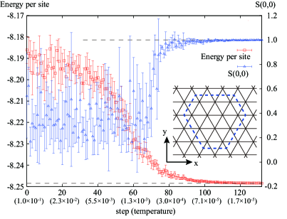
We find that, by introducing a small single-ion anisotropy , the simulated annealing gives a converged solution to the KN state. As for the demonstration, in Fig. 3, we show the cooling process in the simulated annealing at . The calculation was done at , , and . Figure 3 shows the energy per site, , and the spin structure factor at as functions of the cooling step (temperature) in the simulated annealing. The spin structure factor is defined as , where denotes the position vector from th to th site. The KN state is signaled by peaks of at , , , and with equal weights. As shown in the figure, the energy and converge to the values expected in the KN state (dashed lines) as . During the cooling process, , , and have the same values as within the error bars. We performed similar runs for a total of different parameters sets and always found the same behavior as in Fig. 3. The results clearly indicate that the KN state found at 5/8 filling in the variational calculation remains stable within the 12-site unit cell, at least, in the presence of a small Ising-type anisotropy.
III.4 Effect of off-site Coulomb repulsion
As discussed in Sec. III.2, in the KN phase at 5/8 filling in the large region, the lower four bands are fully occupied and the upper bands are occupied up to the Dirac node. This electronic state is approximately regarded as the 1/3-filling state in the spinless fermion model on a kagome lattice: The doped electrons in the upper bands are almost confined in the KN with aligning their spins antiparallel to the localized up-spins because of the large , and the band filling corresponds to 1/3 in the bands originating from the KN. The mapping becomes exact in the limit of . In the spinless fermion model at 1/3 filling, it was pointed out that a fractional charge excitation (; is the elementary charge) emerges when the system has a strong Coulomb repulsion between nearest-neighbor sites OBrien2010 .
Bearing such a possibility in mind, we investigate the effect of a nearest-neighbor Coulomb repulsion on the KN formation. The Hamiltonian is given by
| (3) |
where is the Coulomb repulsion between nearest-neighbor sites, and is a number operator for itinerant electrons on site i. Here, we study the effect of the term by means of the mean-field approximation. Namely, we decouple the interaction term by using the standard Hartree-Fock approximation as
| (4) |
In the mean-field analysis, we assumed that configurations of the classical localized spins are (1a), (2a), (3a), (3d), and (4e) in Fig. 1(c), as these orderings appear in Fig. 1(b). In the calculation, we take grid points in the folded first Brillouin zone.
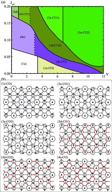
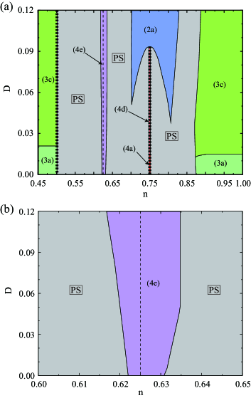
Figure 4 shows the ground-state phase diagram at 5/8 filling obtained by the mean-field approximation. At , there are three phases, (1a), (4e), and (3d), while changing . The (4e) and (3d) states exhibit a charge disproportionation even at , because of the translational symmetry breaking by magnetic ordering; the local charge density at up-spin sites are higher than that at down-spin sites. While increasing , however, an additional translational symmetry breaking appears in each region by charge ordering, i.e., a superstructure of charge density distinct from the magnetic one. From the arguments in the last part in Sec. III.1, we regard that, at least, the (4e-CO) and (1a-CO) phases are trustworthy as they evolve from the reliable (4e) and (1a) states at , respectively.
Among various charge ordered phases, we are interested in the (4e-CO) phase, which emerges from the (4e) KN phase through a second-order phase transition while increasing . The (4e-CO) phase is the KN state accompanied by charge ordering with the wave number , that is the so-called type. The charge ordering pattern is the same as that discussed for the spinless fermion model on a kagome lattice at filling Nishimoto2010 . The charge-ordered state in the spinless fermion system can exhibit fractional charge excitations when an electron (a hole) is added to the 1/3-filling state OBrien2010 . Therefore, it is expected that our mean-field state (4e-CO) is connected to the phase with fractional charge excitations. In fact, a “defect” by electron (hole) doping in the (4e-CO) state can propagate without energy loss, at least for (see also Fig. 4 in Ref. OBrien2010 ). Although it is necessary to go beyond the mean-field approximation to clarify whether the KN state accommodates fractional charge excitations, this is an interesting issue since fractional charge excitations usually emerge in the systems whose lattice structures consist of corner-sharing units. The possibility in the current system on the edge-sharing triangular lattice is left for future study.
III.5 Effect of external magnetic field
Finally, we discuss the effect of an external magnetic field on the KN state. We consider the Zeeman coupling to a magnetic field applied in the direction,
| (5) |
as an additional term to Eq. (1). For simplicity, we neglect the coupling of orbital motion of itinerant electrons to the magnetic field as well as the Zeeman coupling to itinerant electrons.
We investigate the effect of the Zeeman term in Eq. (5) on the model in Eq. (1) by using the simulated annealing. We find that the external magnetic field stabilizes the KN phase as in the case of the single-ion anisotropy discussed in Sec. III.3. Figure 5 shows the magnetization curve calculated by combining the simulated annealing and variational calculations comment3 . Here, the magnetization is defined by . As shown in the figure, the KN phase appears for , with exhibiting magnetization plateau at . Further increasing , the KN phase changes into the (4g) phase which is a canted version of the KN state for , (3d) phase for comment4 , and finally turns into the FM phase for (). The transitions at and are both continuous, whereas that at is of first order. We note that both the (4g) 3:1 and (3d) 2:1 canted phases are magnetic counterparts of supersolid Liu1973 ; Ueda2010 .
The result suggests an interesting controllability of the Dirac electronic state, i.e., one can destroy and create the Dirac electrons by sweeping the magnetic field. While increasing the magnetic field, it shows a transition to a magnetic supersolid phase, in which exotic behavior is expected as well. Furthermore, once the KN phase exhibits fractional charge excitations in the presence of (see Sec. III.4), there is the possibility of controlling the appearance of fractional charge excitations by magnetic field.
IV Summary
We have investigated the Kondo lattice model on a triangular lattice by using the variational calculation and the simulated annealing method. We found that the system exhibits the kagome network state at a special filling for the large Hund’s-rule coupling. In the kagome network state, the system is spontaneously divided into two parts by the four-sublattice collinear ferrimagnetic order: One is the kagome lattice composed of up-spin sites, and the other is isolated down-spin sites in the hexagons of the kagome lattice. This peculiar magnetism gives rise to an unusual electronic state: A Dirac half-semimetallic state. The semimetallic dip of the density of states due to the Dirac node formation contributes to the stabilization of the kagome network phase. We have also found that a -type charge order occurs in the kagome network state as the mean-field solution when we include the Coulomb repulsion between nearest-neighbor sites. This charge ordering pattern is the same as that for the spinless fermion model on a kagome lattice at filling discussed from the interest of fractional charge excitations. Moreover, we have found that the emergence of the kagome network Dirac half-semimetal can be controlled by an external magnetic field. Considering real materials, the parameters used in the present calculations are reasonable to some extent: The Hund’s-rule coupling is dozens of times larger than the transfer integral, and it is one or two orders of magnitude larger than the antiferromagnetic superexchange interaction and the single-ion anisotropy . These energy scales are seen in some real materials, such as manganese oxides. It is desired to explore the kagome network phase discussed in the paper in real systems as a candidate for the peculiar Dirac half-semimetal and possible fractional charge excitations.
Acknowledgements.
We acknowledge helpful discussions with Chisa Hotta, Takahiro Misawa, and Masafumi Udagawa. Y.A. thanks Satoru Hayami, Ryui Kaneko, Yuichi Motoyama, Junki Yoshitake, Hiroaki T. Ueda, and Nic Shannon for helpful comments. Y.A. was supported by Grant-in-Aid for JSPS Fellows. Y.A. acknowledges support from Okinawa Institute of Science and Technology Graduate University. This work was supported by Grants-in-Aid for Scientific Research (Grant Nos. 21340090, 22540372, and 24340076) Global COE Program “the Physical Sciences Frontier,” the Strategic Programs for Innovative Research (SPIRE), MEXT, and the Computational Materials Science Initiative (CMSI), Japan.Appendix A Variational Phase Diagram in the Presence of the Single-ion Anisotropy
In this Appendix, to clarify the effect of the single-ion anisotropy, we study the ground-state phase diagram for the model in Eq. (2) by the variational calculations. Using the method in Sec. II.2, we performed the calculations around , as we are interested in the stability of the KN phase at filling.
Figure 6(a) shows the result of the ground-state phase diagram as a function of the electron filling and the single-ion anisotropy at and . We find that the (4e) KN phase remains stable around in the presence of comment5 . Indeed, it is further stabilized by increasing : The width of the KN phase in becomes wider for larger , as clearly shown in the enlarged figure in Fig. 6(b). Although it is reasonable that the single-ion anisotropy stabilizes the collinear magnetic order, the result is not trivial because the width is determined by the grand potential for the competing phases on the other sides of the PS regions. In the present case, the competing phases are the (3a) phase at and the (4a) phase at in the small region. Increasing , the (3a) and (4a) phases change into their spin canting versions, namely, (3c) and (4d), respectively, as shown in Fig. 6(a). With further increasing , the (4d) phase is eventually taken over by the metallic (2a) phase with a two-sublattice collinear order. Our results indicate that the region of the (4e) KN phase is extended as increases despite the competition to these phases.
References
- (1) C. Zener, Interaction between the -Shells in the Transition Metals. II. Ferromagnetic Compounds of Manganese with Perovskite Structure, Phys. Rev. 82, 403 (1951).
- (2) P. W. Anderson and H. Hasegawa, Considerations on Double Exchange, Phys. Rev. 100, 675 (1955).
- (3) P.-G. Gennes, Effects of Double Exchange in Magnetic Crystals, Phys. Rev. 118, 141 (1960).
- (4) T. A. Kaplan and S. D. Mahanti, Physics of Manganites (Kluwer Academic/Plenum, Amsterdam, 1999)
- (5) Y. Tokura, Colossal Magnetoresistive Oxides (Gordon and Breach, London, 1999)
- (6) S. Yunoki, J. Hu, A. L. Malvezzi, A. Moreo, N. Furukawa, and E. Dagotto, Phase Separation in Electronic Models for Manganites, Phys. Rev. Lett. 80, 845 (1998).
- (7) E. Dagotto, T. Hotta, and A. Moreo, Colossal magnetoresistant materials: the key role of phase separation, Phys. Rep. 344, 1 (2001).
- (8) M. Yamanaka, W. Koshibae, and S. Maekawa, “Flux” State in the Double-Exchange Model, Phys. Rev. Lett. 81, 5604 (1998).
- (9) D. F. Agterberg and S. Yunoki, Spin-flux phase in the Kondo lattice model with classical localized spins, Phys. Rev. B 62, 13816 (2000).
- (10) Y. Taguchi, Y. Oohara, H. Yoshizawa, N. Nagaosa, and Y. Tokura, Spin Chirality, Berry Phase, and Anomalous Hall Effect in a Frustrated Ferromagnet, Science 291, 2573 (2001).
- (11) S. Nakatsuji, Y. Machida, Y. Maeno, T. Tayama, T. Sakakibara, J. van Duijn, L. Balicas, J. N. Millican, R. T. Macaluso, and J. Y. Chan, Metallic Spin-Liquid Behavior of the Geometrically Frustrated Kondo Lattice , Phys. Rev. Lett. 96, 087204 (2006).
- (12) Y. Machida, S. Nakatsuji, Y. Maeno, T. Tayama, T. Sakakibara, and S. Onoda, Unconventional Anomalous Hall Effect Enhanced by a Noncoplanar Spin Texture in the Frustrated Kondo Lattice , Phys. Rev. Lett. 98, 057203 (2007).
- (13) D. Loss and P. M. Goldbart, Persistent currents from Berry’s phase in mesoscopic systems, Phys. Rev. B 45, 13544 (1992).
- (14) J. Ye, Y. B. Kim, A. J. Millis, B. I. Shraiman, P. Majumdar, and Z. Tešanović, Berry Phase Theory of the Anomalous Hall Effect: Application to Colossal Magnetoresistance Manganites, Phys. Rev. Lett. 83, 3737 (1999).
- (15) G. Tatara and H. Kawamura, Chirality-Driven Anomalous Hall Effect in Weak Coupling Regime, J. Phys. Soc. Jpn. 71, 2613 (2002).
- (16) I. Martin and C. D. Batista, Itinerant Electron-Driven Chiral Magnetic Ordering and Spontaneous Quantum Hall Effect in Triangular Lattice Models, Phys. Rev. Lett. 101, 156402 (2008).
- (17) Y. Akagi and Y. Motome, Spin Chirality Ordering and Anomalous Hall Effect in the Ferromagnetic Kondo Lattice Model on a Triangular Lattice, J. Phys. Soc. Jpn. 79, 083711 (2010).
- (18) Y. Kato, I. Martin, and C. D. Batista, Stability of the Spontaneous Quantum Hall State in the Triangular Kondo-Lattice Model, Phys. Rev. Lett. 105, 266405 (2010).
- (19) K. Ohgushi, S. Murakami, and N. Nagaosa, Spin anisotropy and quantum Hall effect in the kagomé lattice: Chiral spin state based on a ferromagnet, Phys. Rev. B 62, R6065 (2000).
- (20) M. Taillefumier, B. Canals, C. Lacroix, V. K. Dugaev, and P. Bruno, Anomalous Hall effect due to spin chirality in the Kagomé lattice, Phys. Rev. B 74, 085105 (2006).
- (21) H. Ishizuka and Y. Motome, Quantum anomalous Hall effect in kagome ice, Phys. Rev. B 87, 081105(R) (2013).
- (22) A. Rahmani, R. A. Muniz, and I. Martin, Anyons in Integer Quantum Hall Magnets, Phys. Rev. X 3, 031008 (2013).
- (23) K. Barros, J. W. F. Venderbos, G-W. Chern, and C. D. Batista, Exotic magnetic orderings in the kagome Kondo-lattice model, Phys. Rev. B 90, 245119 (2014).
- (24) R. Shindou and N. Nagaosa, Orbital Ferromagnetism and Anomalous Hall Effect in Antiferromagnets on the Distorted fcc Lattice, Phys. Rev. Lett. 87, 116801 (2001).
- (25) M. Udagawa and R. Moessner, Anomalous Hall Effect from Frustration-Tuned Scalar Chirality Distribution in , Phys. Rev. Lett. 111, 036602 (2013).
- (26) Y. Akagi, M. Udagawa, and Y. Motome, Hidden Multiple-Spin Interactions as an Origin of Spin Scalar Chiral Order in Frustrated Kondo Lattice Models, Phys. Rev. Lett. 108, 096401 (2012).
- (27) S. Hayami and Y. Motome, Multiple- instability by -dimensional connections of Fermi surfaces, Phys. Rev. B 90, 060402(R) (2014).
- (28) M. Sakata, T. Kagayama, K. Shimizu, K. Matsuhira, S. Takagi, M. Wakeshima, and Y. Hinatsu, Suppression of metal-insulator transition at high pressure and pressure-induced magnetic ordering in pyrochlore oxide , Phys. Rev. B 83, 041102(R) (2011).
- (29) S. Iguchi, N. Hanasaki, M. Kinuhara, N. Takeshita, C. Terakura, Y. Taguchi, H. Takagi, and Y. Tokura, Emergence of a Diffusive Metal State with No Magnetic Order near the Mott Transition in Frustrated Pyrochlore-Type Molybdates, Phys. Rev. Lett. 102, 136407 (2009).
- (30) S. Iguchi, Y. Kumano, K. Ueda, S. Kumakura, and Y. Tokura, Diffusive charge transport with strongly renormalized carrier mass in hole-doped Mott insulators with frustrated pyrochlore lattice, Phys. Rev. B 84, 174416 (2011).
- (31) Y. Motome and N. Furukawa, Phase Competition in the Double-Exchange Model on the Frustrated Pyrochlore Lattice, Phys. Rev. Lett. 104, 106407 (2010).
- (32) S. Kumar and J. van den Brink, Frustration-Induced Insulating Chiral Spin State in Itinerant Triangular-Lattice Magnets, Phys. Rev. Lett. 105, 216405 (2010).
- (33) M. Udagawa, H. Ishizuka, and Y. Motome, Non-Kondo Mechanism for Resistivity Minimum in Spin Ice Conduction Systems, Phys. Rev. Lett. 108, 066406 (2012).
- (34) G-W. Chern, S. Maiti, R. M. Fernandes, and P. Wölfle, Electronic Transport in the Coulomb Phase of the Pyrochlore Spin Ice, Phys. Rev. Lett. 110, 146602 (2013).
- (35) D. Ikoma, H. Tsuchiura, and J. Inoue, Magnetic phase diagram of metallic pyrochlore lattice in the double-exchange model, Phys. Rev. B 68, 014420 (2003).
- (36) Y. Motome and N. Furukawa, Electronic phase separation in the pyrochlore double-exchange model, Phys. Rev. B 82, 060407(R) (2010).
- (37) H. Ishizuka and Y. Motome, Spontaneous spatial inversion symmetry breaking and spin Hall effect in a spin-ice double-exchange model, Phys. Rev. B 88, 100402(R) (2013).
- (38) J. W. F. Venderbos, Maria Daghofer, J. van den Brink, and S. Kumar, Switchable Quantum Anomalous Hall State in a Strongly Frustrated Lattice Magnet, Phys. Rev. Lett. 109, 166405 (2012).
- (39) Y. Akagi and Y. Motome, Noncoplanar spin canting in lightly-doped ferromagnetic Kondo lattice model on a triangular lattice, J. Phys.: Conf. Ser. 320, 012059 (2011).
- (40) H. Ishizuka and Y. Motome, Dirac Half-Metal in a Triangular Ferrimagnet, Phys. Rev. Lett. 109, 237207 (2012).
- (41) S. Kirkpatrick, C. D. Gelatt Jr., and M. P. Vecchi, Optimization by Simulated Annealing, Science 220 (1983) 671.
- (42) Y. Akagi and Y. Motome, Ground-state Phase Diagram of the Kondo Lattice Model on Triangular-to-kagome Lattices, J. Korean Phys. Soc. 63, 405 (2013).
- (43) K. Barros and Y. Kato, Efficient Langevin simulation of coupled classical fields and fermions, Phys. Rev. B 88, 235101 (2013).
- (44) We note that the (4d) phase near in Fig. 1(b) also shows the Dirac node at 5/8 filling. On the other hand, the (4d) phase near does not have a Dirac node in the electronic structure. This is because the canting angle is small () for the latter, while it is large () for the former.
- (45) A. H. Castro Neto, F. Guinea, N. M. R. Peres, K. S. Novoselov, and A. K. Geim, The electronic properties of graphene, Rev. Mod. Phys. 81, 109 (2009).
- (46) A candidate for the lowest-energy state found in the simulated annealing is a 12-sublattice state with a noncoplanar spin configuration. This state is composed of four triangles of ferromagnetically aligned three spins; the four moments comprise an all-out-type configuration.
- (47) A. O’Brien, F. Pollmann, and P. Fulde, Strongly correlated fermions on a kagome lattice, Phys. Rev. B 81, 235115 (2010).
- (48) S. Nishimoto, M. Nakamura, A. O’Brien, and P. Fulde, Metal-Insulator Transition of Fermions on a Kagome Lattice at Filling, Phys. Rev. Lett. 104, 196401 (2010).
- (49) The overall magnetization curve is obtained by the simulated annealing. The result, however, includes small numerical noises, which are presumably due to the small spin components remaining in the converged solutions. We therefore finalize the magnetization curve by using the variational states by assuming that the net component vanishes.
- (50) We note that for the (3d) state is almost degenerate in energy with (3c). The (3c) phase is also a magnetic supersolid similarly to (3d).
- (51) K.-S. Liu and M. E. Fisher, Quantum Lattice Gas and the Existence of a Supersolid, J. Low Temp. Phys. 10, 655 (1973).
- (52) H. T. Ueda, and K. Totsuka, Supersolid phase of three-dimensional spin- and hardcore-boson models, Phys. Rev. B 81, 054442 (2010).
- (53) In this variational phase diagram, the KN phase remains stable down to [see also Fig. 1(a)]. We note, however, that in the simulated annealing, the small anisotropy is required to stabilize the KN phase, as described in Sec. III.3.