Coulomb driven energy boost of heavy ions for laser plasma acceleration
Abstract
An unprecedented increase of kinetic energy of laser accelerated heavy ions is demonstrated. Ultra thin gold foils have been irradiated by an ultra short laser pulse at an intensity of W/cm2. Highly charged gold ions with kinetic energies up to MeV and a bandwidth limited energy distribution have been reached by using Joule laser energy on target. D and D Particle in Cell simulations show how a spatial dependence on the ions ionization leads to an enhancement of the accelerating electrical field. Our theoretical model considers a varying charge density along the target normal and is capable of explaining the energy boost of highly charged ions, leading to a higher efficiency in laser acceleration of heavy ions.
Laser driven ion acceleration has gained a wide scientific interest, as it is a promising ion source for investigation in basic plasma physics and for application in accelerator technology Cowan et al. (2004); Scuderi et al. (2014) related to bio-medical Schardt et al. (2010); Tajima et al. (2009) and hadron research Hill . While the acceleration of protons and light ions are intensively investigated during the last decade, little is reported on acceleration of heavier ions Hegelich et al. (2002). Such knowledge is mandatory to achieve the objectives of upcoming new laser facilities Morou et al. (2011); Daido et al. (2012), e.g. the exploration of nuclear, astrophysical questions as well as the potential use as beam lines for heavy ion radio therapy Kraft (2007).
Energies of heavy ions exceeding the mass number with MeV/u (energy per nucleon) have been reported so far Hegelich et al. (2002, 2006), by using short pulse laser systems with laser pulse energies well above J Hegelich et al. (2005).
In the following we report and discuss a considerable energy boost for acceleration of the highly charged heavy ions with only using J on an ultra thin heavy material target. We accelerated ions up to MeV/u, with a bandwidth limited energy distribution. We found a remarkable deviation in the maximum energy to charge scaling in comparison to established models of Mora Mora (2005) and Schreiber Schreiber et al. (2006); Schreiber (2006).
Presently used laser ion acceleration schemes like Target Normal Sheath Acceleration (TNSA) Wilks et al. (2001), or leaky light sail / Radiation Pressure Acceleration (RPA) Esirkepov et al. (2006); Qiao et al. (2010); Henig et al. (2009), Coherent Acceleration of Ions by Laser (CAIL) Yan et al. (2008); Tajima et al. (2009), Break Out Afterburner (BOA) Jung et al. (2013) make use of an energy transfer from laser to electrons and in a following step electrons accelerate the ions. In the typical physical picture, an ultra intense laser is focused on a thin target, ionizes it and displaces the electrons from the ion background by the laser field. This creates a high electrical field at the rear and front side of the target. The Coulomb attraction field of the ions circumvents the electrons escape and enables the acceleration of the ions. For ultra thin targets and relativistic laser intensities, the acceleration is enhanced by the transparency of the target and the relativistic kinematics of the electrons Yan et al. (2010); Henig et al. (2009); Steinke et al. (2010, 2013). Further optimization for the energies of light ions is proposed by a Coulomb exploding background of heavy ion constituents in a ultra thin foil target Esirkepov et al. (2002); Qiao et al. (2012); Bulanov et al. (2008). A remarkable contribution by the Coulomb explosion to the energy of very heavy ions energy is predicted but still under theoretical discussion Wang et al. (2014); Korzhimanov et al. (2012).
Most acceleration models assume an averaged degree of ionization leading to a fixed electron density - which creates the moving accelerating electrical field for the ions. During the laser plasma interaction ions of different charge to mass ratio separate in the velocity picture, leading to higher MeV/u for the lighter material. The energy per nucleon decreases significantly with the decreasing charge to mass ratio, as the accelerating field is screened by the light ions. Laser plasma experiments using thin foils showed, that in the presence of hydrogen and carbon, ions with a smaller ratio are not accelerated at all or stay with much lower velocity Hegelich et al. (2006). Only specially prepared, heated targets without contamination by light ions, enabled an acceleration of the heavy ions up to the MeV/u range. To our knowledge we obtained for the first time heavy ions with MeV/u in presence of the contamination layer. While the maximum kinetic energy for hydrogen reach MeV/u and MeV/u for , the highest charged gold ion follows with MeV/u.
Experiments have been performed at the Max Born Institute High Field Ti:Sapph. laser. It delivers J at fs on the target after contrast enhancement by a XPW Kalashnikov et al. (2011) frontend and a Double Plasma Mirror (DPM) Levy et al. (2007), leading to a pre pulse free peak to ASE contrast of in the minor ps range. The laser is focused by a off axis parabola to a focal FHWM size of m, giving an averaged intensity of W/cm2 in the focal area. The normalized laser field is for linear polarization, with the electron mass and charge , laser frequency and speed of light , respectively. We focused the laser at free standing nm gold foil Braenzel et al. (2013), which we produced by thermal evaporation at mbar (deposition rate: nm/s), followed by a floating process. HRTEM (High Resolution Transmission Electron Microscopy) reveals a polycrystaline structure of the gold formed by an island growth mode on a carbon based supportive film, which we identify as the rest of the parting agent. The average grain size is of the order of nm. Determination of the composition has been carried out by EDX (Energy Dispersive X-Ray Spectroscopy) with a state of the art FEI ChemiSTEM™system and was quantified standardless with a Cliff-Lorimer calculation. The foil consists of gold , carbon and oxygen , hydrogen is not determinded. STEM (Scanning Transmission Electron Microscopy) measurements reveals a sub crack like structure in () nm distance (see Fig.3b). Structured surfaces can increase the absorption of the laser light, leading to a higher efficiency of the acceleration mechanism. This is discussed widely at the moment, but yet has not been considered for the thinnest targets Andreev and Platonov (2013); Ceccotti et al. (2013). Accelerated particles were detected in single shot measurement by a Thomson spectrometer at in laser propagation direction. The setup consists of an entering pinhole with a diameter of m, a permanent magnet, electrical field plates and a mm Multi Channel Plate (MCP Hamamatsu) covering a detection angle of sr from the target Sokollik (2011). Measurements at a lower laser contrast (without DPM) , showed much lower and particle numbers for hydrogen, carbon, oxygen ions and no gold ion spectra in the measured energy range.
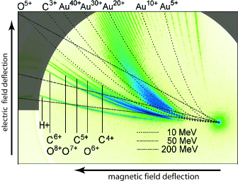
Fig.1 shows a captured picture of the detector. We identify traces of accelerated gold particles for ionization degrees reaching from to , well beyond the trace. With increasing charge to mass ratio we observe light ions traces of oxygen, carbon and hydrogen. For a quick interpretation of the measured data, the overlay in Fig.1 shows lines of constant energy for u to mark constant energy positions for different charge states on the detector. We observed a strong signal for gold ions between and the highest degree of ionization with kinetic energies from MeV to MeV. The traces exhibit a distinct maximum in particle numbers and a bandwidth limited energy distribution for charge states . The low energetic cutoff for ions charged probably lies beyond the detection range. The symmetry of the gold ions cutoff on the detector seems to follow a lemniscate like function (half figure eight): , with as a constant of the radius and a nonlinear, charge depending function. We evaluated the highest energy cutoff and lowest energy cutoff for the different charge states of gold ions in Fig.2.
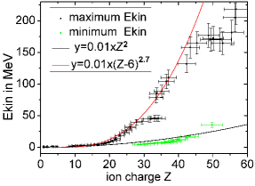
Compared to a expected scaling by the model of Schreiber et al. (2006), our data shows a boosted scaling of . For a better comparison Fig.2 uses the same scaling coefficient for both fit functions. Experiments with gold coated plastic foils (Formvar ()nm ()nm gold coating on target rear side) showed similar results concerning the multiple degrees of ionization, the to scaling, reaching close to the MeV/u range and with a limited bandwidth in the energy spectrum (see supplement). It reveals a general mechanism for the acceleration of heavy ions if ultra thin foil with heavy material is used. The energy distribution related to Fig.1 of selected gold ions is shown in Fig.3. The particle numbers are given relative to a detector calibration with hydrogen and carbon, assuming a similar response for heavy ions Prasad et al. (2010). We approximated the energy content of all accelerated gold ions with Nürnberg et al. (2009); Brambrink et al. (2006) (for methods see supplement) to of the laser energy, while the reaches .

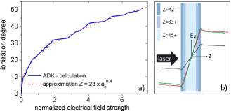
In order to account for the theoretical ionization in dependence on the electrical field strength we used the ADK model Ammosov et al. (1986). The calculation for gold is shown in Fig.3a) and we find an ionization dependence . The field strength for our parameters considers an intensity of , which leads to a maximum ionization of . Higher ionization as observed in our experiment can be attributed to field enhancement in case of partly transparent target plasma, to contributions from the surface structure and to self focusing.
Our D PIC simulation evaluated at high accuracy (mesh size: nm, particles per cell, error ) has been performed using the laser parameters of the experiment and a target thickness of nm. For simplification we freezed the ionization in time at the end of the laser pulse. The D PIC simulation shows in longitudinal direction a symmetrical, varying ionization degree (see Fig.4b) Zhidkov and Sasaki (2000). Compared to an averaged degree of ionization, it leads to an enhancement of the electrical field at the front and rear side of the target by contributions of the repelling Coulomb force. The field enhancement becomes strong for highly charged ions.
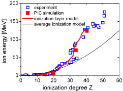
For the D PIC simulation we used W/cm2, fs, m focus diameter, Gaussian laser profile. The pulse interacts with a pure nm thick gold target. The step size of the calculation was nm with particles per cell. In Fig.5 we compare the calculated energies with our experimental results and the model of Schreiber et al. (2006). The to dependence has to be separated into three parts: while for the Au ion energies fit to a , ions with are with an exponent , followed by a smaller linear dependence for .
Our analytical model focuses on the Poisson equation, as the electrical field of the laser does not penetrate deep inside even in our thin foil. We take a spatially varying ionization of heavy target material into account:
| (1) |
Here we use a D geometry with the coordinates , where the Debye radius is and assuming the process to be adiabatic. The normalized electron density is and the normalized electric field is . The ion density has a rectangular shape in both directions, where are dynamic foil thickness and electron spot size, respectively. The hot electron density is determined from quasi-neutrality and the ionization degree is . We introduce a spatial dependence of the hot electron density: . The spatial depending degree of ionization is given as:
| (2) |
The electron temperature depends on the pulse duration and on a laser absorption coefficient (here and in the following see Andreev et al. (2010)): . For simplification, we assume a rectangular transversal and longitudinal electron density profile, which width changes in time with . For the ultrathin foil follows: , we take the expansion of the recirculating hot electrons as a time dependent parameter . At this point we freeze the degree of ionization in time. The time dependent solution of Eq.1 at looks similar to Andreev et al. (2010):
| (3) |
denotes the initial electron spot size and is the plasma conductivity. The equation contains a spatial dependence of the charge distribution in the target instead of an averaged, constant one. The dependence of the analytical field (3) on coordinate is similar to the PIC simulated one (Fig.4b). The charged ion front in the target can be calculated by the equation of motion after inserting (3) and with :
| (4) |
Expression (4) defines the energy of an ion with maximum degree of ionization, which is at the front of acceleration . Electron density in each instant is defined by (1). From the equation of continuity follows and the ion velocity with the coordinate of reads: , . The energy for a particle placed initially at with an charge of has to be evaluated parametrically with (2) and (4). For ions inside the target results:
| (5) |
With for ions of very high energy Mora (2005). This leads to ion energy to charge scaling, which is in good agreement with our PIC simulated and experimental results (see Fig.5).
Ions with a very high degree of ionization , are formed
in a field maximum at the target rear side. These ions have the
initial coordinate . According to (4)
for ions with a high charge ,
the formula (5) gives for all the linear relation
. The smaller energy to scaling is
explained by the decreasing charged background compared to ions
placed inside the target.
In conclusion, we demonstrated efficient acceleration of heavy
ions by an ultra short laser pulse system. So far laser systems that
compensate lower laser energy with a shorter pulse duration to reach
the same intensity, had not been able to accelerate heavy ions with
into the MeV/u region. By using an ultra thin foil of heavy
material we achieved highly charged heavy ions with a limited
bandwidth in the energy spectrum, reaching up to MeV/u.
Furthermore we simplified a complex target preparation, which
achieves a prerequisite for future applications. We demonstrated
experimentally and theoretically how a spatial distribution of the
ionization inside the target leads to a field enhancement for the
heavy ions by Coulomb explosion. This has the potential to greatly
improve the efficiency of heavy ion acceleration by stronger kinetic
energy with charge scaling. Our results indicate that e.g. energies
with MeV/u can be achieved with times higher laser
energy than in our experiment. This relaxes the previously estimated
laser power requirements for upcoming facilities Morou et al. (2011) by a
factor of which is enormous in costs if ultra fast
class lasers are considered.
The research leading to these results received funding from the
Deutsche Forschungsgemeinschaft within the program CRC/Transregio 18
and LASERLAB-EUROPE (grant agreement n , EC’s Seventh
Framework Program). Computational resources was provided from the
ISC within the project MBU.
References
- Cowan et al. (2004) T. E. Cowan, J. Fuchs, H. Ruhl, A. Kemp, P. Audebert, M. Roth, R. Stephens, I. Barton, A. Blazevic, E. Brambrink, et al., Physical Review Letters 92, 204801 (2004).
- Scuderi et al. (2014) V. Scuderi, S. Bijan Jia, M. Carpinelli, G. A. P. Cirrone, G. Cuttone, G. Korn, T. Licciardello, M. Maggiore, D. Margarone, P. Pisciotta, et al., Nuclear Instruments and Methods in Physics Research Section A 740, 87 (2014).
- Schardt et al. (2010) D. Schardt, T. Elsässer, and D. Schulz-Ertner, Reviews of Modern Physics 82, 383 (2010).
- Tajima et al. (2009) T. Tajima, D. Habs, and X. Q. Yan, Rev. Acc. Science Technol. 2, 201 (2009).
- (5) C. Hill, Cern linac 2, URL http://www.http://linac2.web.cern.ch/linac2/.
- Hegelich et al. (2002) M. Hegelich, S. Karsch, G. Pretzler, D. Habs, K. Witte, W. Guenther, M. Allen, A. Blazevic, J. Fuchs, J. C. Gauthier, et al., Physical Review Letters 89, 085002 (2002).
- Morou et al. (2011) G. Morou, G. Korn, W. Sandner, and J.L.Collier, The whitebook of ELI Nuclear Physics group (Thoss-Media GmBH, 2011).
- Daido et al. (2012) H. Daido, M. Nishiuchi, and A. Pirozhkov, Rep Prog Phys 75, 056401 (2012).
- Kraft (2007) G. Kraft, Tumor Therapy with Heavy Ions (Verein zur Förderung der Tumortherapie mit schweren Ionen e.V., 2007).
- Hegelich et al. (2006) B. M. Hegelich, B. J. Albright, J. Cobble, K. Flippo, S. Letzring, M. Paffett, H. Ruhl, J. Schreiber, R. K. Schulze, and J. C. Fernandez, Nature 439, 441 (2006).
- Hegelich et al. (2005) B. M. Hegelich, B. Albright, P. Audebert, A. Blazevic, E. Brambrink, J. Cobble, T. Cowan, J. Fuchs, J. C. Gauthier, C. Gautier, et al., Physics of Plasmas 12 (2005).
- Mora (2005) P. Mora, Physical Review E 72, 056401 (2005).
- Schreiber et al. (2006) J. Schreiber, F. Bell, F. Grüner, U. Schramm, M. Geissler, M. Schnürer, S. Ter-Avetisyan, B. M. Hegelich, J. Cobble, E. Brambrink, et al., Physical Review Letters 97, 045005 (2006).
- Schreiber (2006) J. Schreiber, Ion acceleration driven by high-intensity laser pulses (2006), URL http://edoc.ub.uni-muenchen.de/5842/1/Schreiber_Joerg.pdf.
- Wilks et al. (2001) S. C. Wilks, A. B. Langdon, T. E. Cowan, M. Roth, M. Singh, S. Hatchett, M. H. Key, D. Pennington, A. MacKinnon, and R. A. Snavely, Physics of Plasmas 8, 542 (2001).
- Esirkepov et al. (2006) T. Esirkepov, M. Yamagiwa, and T. Tajima, Physical Review Letters 96, 105001 (2006).
- Qiao et al. (2010) B. Qiao, M. Zepf, M. Borghesi, B. Dromey, M. Geissler, A. Karmakar, and P. Gibbon, Physical Review Letters 105, 155002 (2010).
- Henig et al. (2009) A. Henig, S. Steinke, M. Schnürer, T. Sokollik, R. Hörlein, D. Kiefer, D. Jung, J. Schreiber, B. M. Hegelich, X. Q. Yan, et al., Physical Review Letters 103, 245003 (2009).
- Yan et al. (2008) X. Q. Yan, C. Lin, Z. M. Sheng, Z. Y. Guo, B. C. Liu, Y. R. Lu, J. X. Fang, and J. E. Chen, Physical Review Letters 100, 135003 (2008).
- Jung et al. (2013) D. Jung, L. Yin, D. C. Gautier, H. C. Wu, S. Letzring, B. Dromey, R. Shah, S. Palaniyappan, T. Shimada, R. P. Johnson, et al., Physics of Plasmas 20, 083103 (2013).
- Yan et al. (2010) X. Q. Yan, T. Tajima, M. Hegelich, L. Yin, and D. Habs, Applied Physics B 98, 711 (2010).
- Steinke et al. (2010) S. Steinke, A. Henig, M. Schnürer, T. Sokollik, P. V. Nickles, D. Jung, D. Kiefer, R. Hörlein, J. Schreiber, T. Tajima, et al., Laser and Particle Beams 28, 215 (2010).
- Steinke et al. (2013) S. Steinke, P. Hilz, M. Schnürer, G. Priebe, J. Braenzel, F. Abicht, D. Kiefer, C. Kreuzer, T. Ostermayr, J. Schreiber, et al., Physical Review Special Topics - Accelerators and Beams 16, 011303 (2013).
- Esirkepov et al. (2002) T. Z. Esirkepov, S. V. Bulanov, K. Nishihara, T. Tajima, F. Pegoraro, V. S. Khoroshkov, K. Mima, H. Daido, Y. Kato, Y. Kitagawa, et al., Physical Review Letters 89, 175003 (2002).
- Qiao et al. (2012) B. Qiao, S. Kar, M. Geissler, P. Gibbon, M. Zepf, and M. Borghesi, Physical Review Letters 108, 115002 (2012).
- Bulanov et al. (2008) S. S. Bulanov, A. Brantov, V. Y. Bychenkov, V. Chvykov, G. Kalinchenko, T. Matsuoka, P. Rousseau, S. Reed, V. Yanovsky, D. W. Litzenberg, et al., Physical Review E 78, 026412 (2008).
- Wang et al. (2014) H. Y. Wang, C. Lin, B. Liu, Z. M. Sheng, H. Y. Lu, W. J. Ma, J. H. Bin, J. Schreiber, X. T. He, J. E. Chen, et al., Physical Review E 89, 013107 (2014).
- Korzhimanov et al. (2012) A. V. Korzhimanov, E. S. Efimenko, S. V. Golubev, and A. V. Kim, Physical Review Letters 109, 245008 (2012).
- Kalashnikov et al. (2011) M. Kalashnikov, K. Osvay, R. Volkov, H. Schönnagel, and W. Sandner, CLEO - Laser Applications to Photonic Applications p. CWG3 (2011).
- Levy et al. (2007) A. Levy, T. Ceccotti, P. D’Oliveira, F. Reau, M. Perdrix, F. Quere, P. Monot, M. Bougeard, H. Lagadec, P. Martin, et al., Optics Letters 32, 310 (2007).
- Braenzel et al. (2013) J. Braenzel, C. Pratsch, P. Hilz, C. Kreuzer, M. Schnürer, H. Stiel, and W. Sandner, Review of Scientific Instruments 84, 056109 (2013).
- Andreev and Platonov (2013) A. A. Andreev and K. Y. Platonov, Contributions to Plasma Physics 53, 173 (2013).
- Ceccotti et al. (2013) T. Ceccotti, V. Floquet, A. Sgattoni, A. Bigongiari, O. Klimo, M. Raynaud, C. Riconda, A. Heron, F. Baffigi, L. Labate, et al., Physical Review Letters 111, 185001 (2013).
- Sokollik (2011) T. Sokollik, Investigations of Field Dynamics in Laser Plasmas with Proton Imaging, Springer Theses (Springer Berlin Heidelberg, 2011).
- Prasad et al. (2010) R. Prasad, D. Doria, S. Ter-Avetisyan, P. Foster, K. Quinn, L. Romagnani, C. Brenner, J. Green, P. Gallegos, M. Streeter, et al., Nuclear Instruments and Methods in Physics Research Section A 623, 712 (2010).
- Nürnberg et al. (2009) F. Nürnberg, M. Schollmeier, E. Brambrink, A. Blažević, D. C. Carroll, K. Flippo, D. C. Gautier, M. Gei el, K. Harres, B. M. Hegelich, et al., Review Scientific Instruments 80, 033301 (2009).
- Brambrink et al. (2006) E. Brambrink, J. Schreiber, T. Schlegel, P. Audebert, J. Cobble, J. Fuchs, M. Hegelich, and M. Roth, Physical Review Letters 96, 154801 (2006).
- Ammosov et al. (1986) M. Ammosov, A. Delone, and V. Krainov, Sov. Phys. JETP 64, 1191 (1986).
- Zhidkov and Sasaki (2000) A. Zhidkov and A. Sasaki, Physics of Plasmas 7, 1341 (2000).
- Andreev et al. (2010) A. A. Andreev, S. Steinke, M. Schnuerer, A. Henig, P. V. Nickles, K. Y. Platonov, T. Sokollik, and W. Sandner, Physics of Plasmas 17, 123111 (2010).