Loop-Back Interference Suppression
for OFDM Signals via Sampled-Data Control
Abstract
In this article, we consider the problem of loop-back interference suppression for orthogonal frequency division multiplexing (OFDM) signals in amplify-and-forward single-frequency full-duplex relay stations. The loop-back interference makes the system a closed-loop system, and hence it is important not only to suppress the interference but also to stabilize the system. For this purpose, we propose sampled-data design of digital filters that ensure the stability of the system and suppress the continuous-time effect of interference at the same time. Simulation results are shown to illustrate the effectiveness of the proposed method.
I Introduction
In wireless communications, relay stations are used to relay radio signals between radio stations that cannot directly communicate with each other due to the signal attenuation. On the other hand, it is important to efficiently utilize the scarce bandwidth due to the limitation of frequency resources. For this purpose, single-frequency network is expected in which signals with the same carrier frequency are transmitted through communication network. Then, a problem of loop-back interference caused by coupling waves arises in a full-duplex relay station in a single-frequency network [1].
Fig. 1 illustrates loop-back interference by coupling waves. In this figure, radio signals with carrier frequency [Hz] are transmitted from the base station (denoted by BS). One terminal (denoted by T1) directly receives the signal from the base station, but the other terminal (denoted by T2) is so far from the base station that they cannot communicate directly. Therefore, a relay station (denoted by RS) is attached between them to relay radio signals. Then, radio signals with the same carrier frequency [Hz] are transmitted from RS to T2, but also they are fed back to the receiving antenna directly or through reflection objects. As a result, loop-back interference is caused in the relay station, which may deteriorate the quality of communication and, even worse, may destabilize the closed-loop system.
For the problem of loop-back interference, a simple adaptive filter method with only two antennas has been proposed to cancel the effect of coupling waves in digital domain [2]. This method does not need multi-antenna array and becomes quite effective when the relay gain is low. However, it is pointed out that the relay system becomes unstable if the relay gain is very high [3]. Moreover, in theory, if the signals are completely band-limited below the Nyquist frequency, then discrete-time domain approaches might work well, but the assumption of perfect band limitedness is hardly satisfied in real communication signals because real pulse shaping filters do not act perfectly and the nonlinearity in electric circuits adds frequency components beyond the Nyquist frequency.

To prevent closed-loop stability and consider high-frequency components, we have proposed a new design method for coupling wave cancelation based on the sampled-data control theory [4, 5]. It is introduced to model the transmitted radio signals and coupling waves as continuous-time signals, and optimize the worst case continuous-time error due to coupling waves by a digital canceler. This is formulated as a sampled-data optimal control problem. Design examples are shown to illustrate the problem methods and evaluate the communication performance. While our submitted paper [5] shows signal reconstruction performance of the proposed method, in this manuscript analyzes communication performance.
The remainder of this article is organized as follows. In Section II, we derive a mathematical model of a relay station considered in this study and propose sampled-data control for cancelation of loop-back interference. In Section III, simulation results are shown to illustrate the effectiveness of the proposed method. In Section IV, concluding remarks are offered.
Notation
Throughout this article, the following notation are used. We denote by the Lebesgue space consisting of all square integrable real functions on endowed with norm . The symbol denotes the argument of time, the argument of Laplace transform and the argument of transform. These symbols are used to indicate whether a signal or a system is of continuous-time or discrete-time. The operator with nonnegative real number denotes the continuous-time delay operator with delay time .
II Relay Station Model and Filter Design
In this section, we provide a mathematical model of a relay station with loop-back interference phenomenon and formulate the cancelation filter design problem.

There are mainly two types of relaying protocols in wireless communication [6]. The first type simply amplifies received digital symbols and transmits them and is named as amplify-and-forward (AF) protocol. The other type is called as decode-and-forward (DF) protocol, in which the received signals are demodulated and decoded before transmission. In the DF protocol, by decoding there does not exist a risk to be unstable. However, the AF protocol requires quite lower implementation complexity than the DF protocol [6]. Throughout this study it is assumed that relay stations operate with the AF protocol.
Fig. 2 depicts a typical AF single-frequency full-duplex relay station implemented with a digital canceler. A radio wave with carrier frequency [Hz] from a base station is accepted at the receiving antenna and amplified by the low noise amplifier (LNA). Then, the received signal is demodulated to a baseband signal by the demodulator, and converted to a digital signal by the analog-to-digital converter (ADC). The obtained digital signal is then processed and the effect of loop-back interference mentioned in the previous section is suppressed by the digital signal processor (DSP), which is converted to an analog signal by the digital-to-analog converter (DAC). Finally, the analog signal is modulated to a radio wave with carrier frequency [Hz] and transmitted to terminals with which we communicate by the transmission antenna. Inevitably, this signal is also fed back to the receiving antenna of the relay station. This is called coupling wave and causes loop-back interference, which deteriorates the communication quality.

Fig. 3 shows a simplified block diagram of the relay station. In Fig. 3, is the transmitted radio wave from the base station. LNA and PA in Fig. 2 are modeled as static gains, and , respectively. The modulator is denoted by and the demodulator by . It is assumed that the coupling wave channel is a flat fading channel, that is, all frequency components of a signal through this channel experience the same magnitude fading. Then the channel can be treated as an all-pass system. In this study, we adopt a delay system, , as a channel model, where is the attenuation rate and is a delay time. The block named “Digital System” includes ADC, DSP, and ADC in Fig. 3.
In order to realize a single-frequency network, it is considered to use orthogonal frequency division multiplexing (OFDM) with a quadrature amplitude modulation (QAM). OFDM with QAM has a high equalization performance by the block transmission with a cyclic prefix and a good tolerance to inter-symbol interference from multipath environment. Moreover, this system is easily implemented in a digital signal processor [7]. QAM transforms a transmission signal into two orthogonal carrier waves, that is a sine wave and a cosine wave.

In this figure, is the received baseband signal and ,
| (3) |
is an anti-aliasing analog filter with an ideal sampler with sampling period , defined by
| (6) |
denotes a digital filter, which we design for loop-back interference cancelation, a zero-order hold , is defined by
| (9) |
and a post analog low-pass filter denoted by model which is a digital-to-analog converter in Fig 2. It is assumed that and are proper, stable and real-rational transfer function matrices.
For the obtained system described as Fig. 4, we find the digital controller, , that stabilizes the feedback system and also minimize the effect of self-interference. To obtain a reasonable solution, we restrict the input continuous-time signal to the following set
| (10) |
where is a continuous-time LTI system with real-rational stable, and strictly proper transfer function . It is notable that OFDM signals are elements of this set. After that, Fig. 5 is obtained, with an error signal .

Let be the system from to . Here we formulate our design problem to find a digital controller that minimizes . This is a standard sampled-data control problem, and can be efficiently solved via fast sample fast hold (FSFH) approximation [8]. Note that if there exists a controller that minimizes , then the feedback system shown by Fig. 4 is stable and the effect of loop-back interference is bounded by the norm[5].
III Simulations
In the section, simulation results are shown to illustrate the effectiveness of the proposed method.
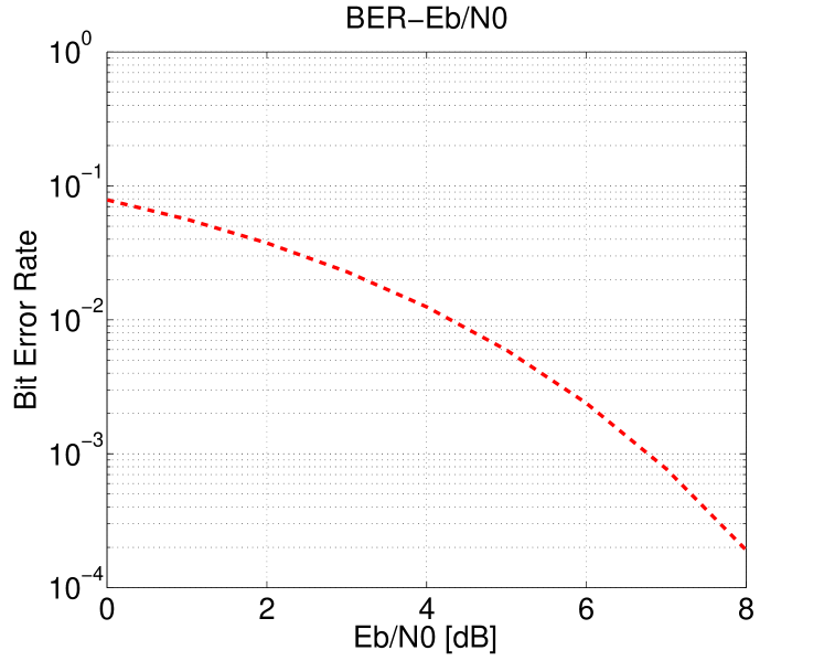
The bit error rate (BER) is used as a measure of the performance of digital communications. The rate is defined as the number of bit errors divided by the total number of transferred bits over a communication channel that generates attenuation, noise, interference, and so on. In addition, the ratio of the energy per bit to the noise power spectral density, denoted by , is preferred to indicate the transmission environment performance. The quantity corresponds to signal-to-noise ratio (SNR) in analog communication. We show curves of BER vs and BER vs the relay gain (see Fig. 3) in order to assess the effectiveness of designed filters.
It is assumed that the sampling period is normalized to 1, the normalized carrier frequency is 10000 [Hz], the attenuation rate of the coupling wave channel , the time delay , and low noise amplifier and the anti-alias analog filter as and . The post filter is modeled by
| (11) |
With these parameters, we compute the -optimal nominal controller by FSFH with discretization number . OFDM signals are generated with random binary phase shift keying (BPSK) data of amplitude 1. The data length is 64 and the guard interval length is 16, namely, the block length becomes 80. It is assumed that the noise is white Gaussian and added at the receiving antenna. Fig. 6 shows the ideal curve of BER vs from the receiving antenna to the transmission antenna without interference nor channel distortion on the additive white gaussian noise channel. In this section, we calculate BER with the input signal to the receiving antenna and the filtered signal by the designed filter, which is denoted by in Fig. 4.
Here, is set at , or, 66 [dB]. First, we employ a pulse-shaping filter of a sinc type of frequency characteristic with the symbol period . A pulse passed through the filter is described as a squared pulse since the input signals are impulse ones in the communication considered here. The frequency characteristic of input signals is modeled by the following real-rational transfer function
| (12) |
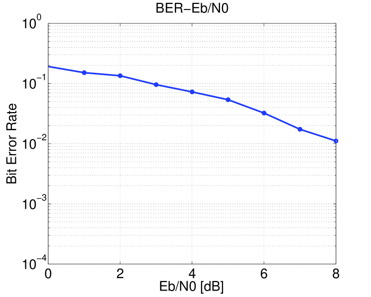
Fig. 7 shows the BER vs using the squared pulse. Next, we consider the situation where a root-raised-cosine filter is put at the base station and terminals. Then, the pulse is described as a root-raised-cosine pulse [7]. The symbol period is assumed to be , the roll-off factor is fixed to 0.2, and the frequency characteristic is set as
| (13) |
Fig. 8 shows the curve of BER vs using the root-raised-cosine pulse. In the simulations, the symbol number is .
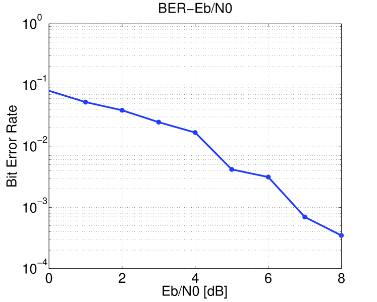
From Fig. 7, it can be seen that with the squared pulse the designed filter can suppress the effect of loop-back interference almost completely. The curve has lower values than the ideal curve at several points, but it is inferred that if we simulate more times, the averaged value converges to an upper value.
From Fig. 8, if we use the root-raised-cosine pulse-shaping filter, the designed filter has lower performance compared to above. It seems that it happens because the root-raised-cosine pulse has lower high-frequency components than the squared pulse and then the designed filter becomes more conservative.
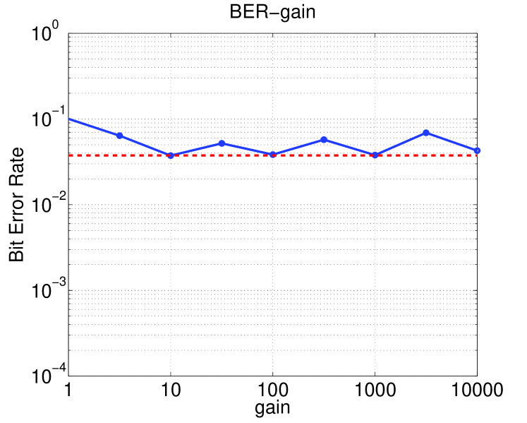
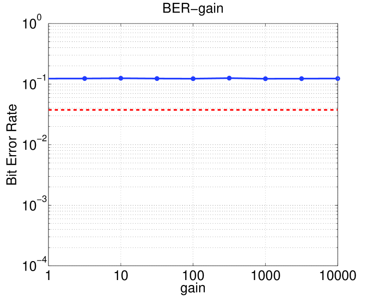
Finally, we check the effect of perturbation in the relay gain . Fig. 9 depicts the curve of BER vs the gain with a squared pulse when is 2 [dB] and Fig. 10 is the curve with a root-raised-cosine pulse. The dash-dot line shows the ideal values without interference and the solid line shows the simulated values with the loop-back interference cancelation. The number of symbols in the simulation is . From this figure, if the stability is preserved then BER does not depend on the relay gain with the proposed canceler.
IV Conclusion
In this paper, we have proposed filter design for loop-back interference cancelation in AF single-frequency full-duplex relay stations based on the sampled-data control theory. Simulation results have been shown to illustrate the effect of the proposed cancelers to communication performance.
Acknowledgement
This research is supported in part by the JSPS Grant-in-Aid for Scientific Research (B) No. 24360163 and (C) No. 24560543, Grant-in-Aid for Scientific Research on Innovative Areas No. 26120521, and an Okawa Foundation Research Grant.
References
- [1] M. Jain et al., “Practical, real-time, full duplex wireless,” in Proc. 17th Annual International Conference on Mobile Computing and Networking (MobiCom), 2011, pp. 301–312.
- [2] H. Sakai, T. Oka, and K. Hayashi, “A simple adaptive filter method for cancellation of coupling wave in OFDM signals at SFN relay station,” in Proc. 14th European Signal Processing Conference (EUSIPCO 06), 2006.
- [3] B. Chun, E. Jeong, J. Joung, Y. Oh, and Y. H. Lee, “Pre-nulling for self-interference suppression in full-duplex relays,” in Proc. Asia-Pacific Signal and Information Processing Association, 2009 Annual Summit and Conference, 2009.
- [4] M. Nagahara, H. Sasahara, K. Hayashi, and Y. Yamamoto, “Sampled-data design of coupling wave cancelers in single-frequency full-duplex relay stations,” in Proc. of SICE Annual Conference 2014, 2014.
- [5] H. Sasahara, M. Nagahara, K. Hayashi, and Y. Yamamoto, “Digital cancelation of self-interference for single-frequency full-duplex relay stations via sampled-data control,” SICE JCMSI, 2015, (submitted, available at: http://arxiv.org/abs/1503.02379).
- [6] R. U. Nabar, H. Bolcskei, and F. W. Kneubuhler, “Fading relay channels: Performance limits and space-time signal design,” Selected Areas in Communications, IEEE Journal on, vol. 22, no. 6, pp. 1099–1109, 2004.
- [7] A. Goldsmith, Wireless Communications. Cambridge University Press, 2005.
- [8] T. Chen and B. A. Francis, Optimal Sampled-Data Control Systems. Springer, 1995.