Towards scalable entangled photon sources with self-assembled InAs/GaAs quantum dots
Abstract
Biexciton cascade process in self-assembled quantum dots (QDs) provides an ideal system for deterministic entangled photon pair source Benson et al. (2000); Shields (2007), which is essential in quantum information science. The entangled photon pairs have recently be realized in experiments Stevenson et al. (2006); Bennett et al. (2010); Trotta et al. (2014) after eliminating the FSS of exciton using a number of different methods. However, so far the QDs entangled photon sources are not scalable, because the wavelengths of the QDs are different from dot to dot. Here we propose a wavelength tunable entangled photon emitter on a three dimensional stressor, in which the FSS and exciton energy can be tuned independently, allowing photon entanglement between dissimilar QDs. We confirm these results by using atomistic pseudopotential calculations. This provides a first step towards future realization of scalable entangled photon generators for quantum information applications.
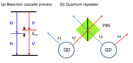
Entangled photon pairs play a crucial role in quantum information applications, including quantum teleportationJennewein et al. (2002), quantum cryptographyGisin et al. (2002) and distributed quantum computationCirac et al. (1999), etc. The biexciton cascade process in a self-assembled QD has been proposed Benson et al. (2000) to generate the “event-ready” entangled photon pairs. As shown in Fig. 1(a), a biexciton decays into two photons via two paths of different polarizations and . If the two paths are indistinguishable, the final result is a polarization entangled photon pair stateStevenson et al. (2006); Benson et al. (2000). However, the - and -polarized photons have a small energy difference, known as the fine structure splitting (FSS), which is typically about -40 +80 eV in the InAs/GaAs QDs Young et al. (2005); Högele et al. (2004); Tartakovskii et al. (2004), much larger than the radiative linewidth ( 1.0 eV) Stevenson et al. (2006); Akopian et al. (2006). Such a splitting provides therefore “which way” information about the photon decay path that can destroy the photon entanglement, leaving only classically correlated photon pairs Stevenson et al. (2006); Akopian et al. (2006). Great efforts have been made trying to eliminate the FSS of excitons in QDs, and significant progress has been made in understanding Bester et al. (2003); He et al. (2008); Singh and Bester (2010); Gong et al. (2011) and manipulating the FSS in self-assembled QDs in recent years. Various techniques has been developed to eliminate the FSS in QDsSeidl et al. (2006); Gerardot et al. (2007); Vogel et al. (2007); Dou et al. (2008); Ding et al. (2010); Bennett et al. (2010); Jöns et al. (2011); Trotta et al. (2012). Especially, it was recently found by applying combined uniaxial stresses or stress together with electric field, it is possible to reduce to the FSS to nearly zero for general self-assembled InAs/GaAs QDs Wang et al. (2012); Trotta et al. (2012, 2014).
However, to build practical QDs devices for applications in quantum information science, they must be scalable. One possible application for scalable entangled photon emitters is shown in Fig. 1(b) as quantum repeater to distribute entanglement over long distance. The set-up of Fig. 1(b) can also be used to generate multi-photon entanglement Pan et al. (2012); Huang et al. (2011). The on-demand entangled photon emitters have great advantages of over the traditional parametric down convention process to generate multi-photon entanglement, which has finite probability of generating more than one photon pair in a excitation cycleGisin et al. (2002). In these applications, the wavelengths of the joint photons have to be identical, i.e., = in Fig. 1(b). Besides, one often need to interface the entangled photon pairs to other quantum system, such as NV-center, cold atom, or other solid quantum systems etc. These applications also requires that the wavelengths of the QDs to be tunable, while at the same time keep the FSS nearly zero. However, it was found that there are strong correlations between exciton energy and FSS of excitonGerardot et al. (2007); Pooley et al. (2014). Furthermore, because of the random alloy distribution and other uncontrollable effects, the physical properties of QDs differ dramatically from dot to dot. Therefore, it is still a great challenge to build such scalable entangled photon generators using dissimilar quantum dots.
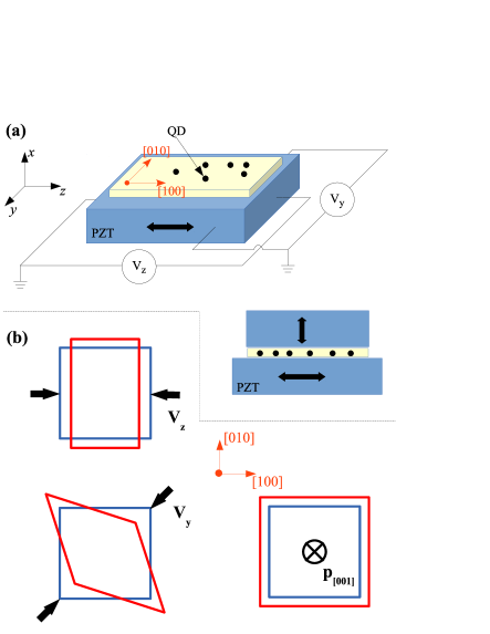
The independent tunability the FSS and exciton energy is therefore essential for the scalable entangled photon emitters. We demonstrate such a tunability by proposing a three dimensional stressor for QDs. Our basic setup is schematically shown Fig. 2 (a). We consider QDs that are tightly glued to the plane of the piezoelectric lead zirconic titanate (PZT) ceramic stack Seidl et al. (2006). The [100] axis of the QDs samples are aligned to the polar () axis of PZT, whereas [010], [001] axes of the QDs are aligned to the and axes of the PZT respectively. Two independent in-plane electric voltages, and , are applied to the PZT device as shown in the Fig. 2(a), which generate electric fields and along the PZT and axes respectively. The electric field causes the in-plane strain to the QDs as,
| (1) |
where, , , are the piezoelectric coefficients of PZT and . , and are the elastic compliance constants of GaAs. The electric fields and lead to in-plane strains to the QDs are shown in Fig. 2(b): causes strain along [010] and [100] axes of the QDs sample, whereas causes strain along [110] axis of the QDs. As demonstrated in Ref. Wang et al. (2012), one can almost fully eliminate the FSS in a general InAs/GaAs QD by suitable combination of such strains. To tune the energy of the exciton, we apply a stress along the [001] direction of the QDs sample [see Fig. 2(b)], which can be easily implemented in experiments. This pressure generates the strain to the QDs. Now we have a device that can tune freely the 3D strain to the QDs. Next we show that the device is able to tune the exciton emission energy in a wide range while keep the FSS minimum ( 0.1 eV).
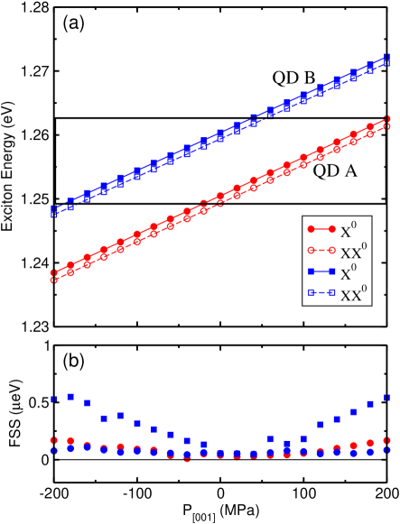
To see if our device really works, we perform atomistic pseudopotential calculations (see Methods) to confirm the above predictions. We have calculated 8 (In,Ga)As/GaAs dots. The details of the structure and alloy composition are given in Table S4 of the Supplementary materials sup . The results of two dots QD-A and QD-B are presented in Fig. 3 (a). The results are obtained in such way: First, in the absence of , we carefully choose the in-plane electric fields and to tune strain tensor , that reduces the FSS of exciton to nearly zero Wang et al. (2012). For QD-A, the applied in-plane electric fields are =9.6 kV/cm, and =3.3 kV/cm, whereas for QD-B, the electric fields are =3.5 kV/cm, and =4.3 kV/cm, respectively. We then switch on the perpendicular stress to study the evolution of exciton energy and FSS as functions of . Figure 3(a) depicts the exciton and biexciton emission energies for QD-A and QD-B as functions , while keep the in-plane electric field and (thus the in-plane strain) unchanged. Although, in practice, one can only apply positive (compression) pressure to the QDs in our device, we plot the results of negative pressure just for theoretical interest. We find that the exciton energy can be tuned in a wide range of about 20 meV when change from -200 MPa to 200 MPa, with the slope of 6 meV/100 MPa for both QDs. The change of exciton energy is comparable with the full width at the half maximum of a general QDs ensemble. These results suggest that in principle, the exciton energies of most QDs grown in the same sample can be tuned to identical using our scheme. The corresponding results for FSS are presented in Fig. 3(b). Remarkably, the FSS change with is rather small. For QD-A, the FSS [the red dots in Fig. 3(b)] is about 0.03 eV at =0. It become slightly larger with the increasing of , and reach 0.1 eV at = 200 MPa. The FSS of QD-B [the blue squares in Fig. 3(b)] has somehow stronger dependence of , which reaches approximately 0.5 eV at = 200 MPa. This is nevertheless still smaller than the homogeneous broadening of the spectral ( 1 eV), which is the upper limit for entangled photon generation. In this situation, it is possible to further reduce the FSS at given , by tuning the in-plane electric fields and . The blue dots are the FSS of QD-B after such optimization. By slightly changing from 4.3 kV/cm to 4.5 kV/cm, the FSS reduces from approximately 0.5 eV to approximately 0.08 eV at =200 MPa. This change will shift the exciton energy by only about 0.02 meV. This energy shift can be compensated by increasing by 0.36 MPa, which hardly change the FSS. In such way, we can tune the FSS to nearly zero at any given exciton energy in the range in only one or two iterations. We also calculate the exciton radiative lifetimes under . The exciton lifetimes for QD A and QD B are around 1 ns, and change little under , which is good for the proposed device applications.
More results for dots with different geometries and alloy compositions are given in Table S5 of the supplementary materials sup . We fit the atomic pseudopotential calculated results by a 22 model Gong et al. (2011); Wang et al. (2012). Although it is easy to understand that in-principle the FSS and exciton energy can be tuned simultaneously to desired values by suitable combination of three linearly independent external fields from the 22 model, there is an additional advantage that in our scheme the exciton energy and FSS can be tuned almost separately, i.e., the in-plane strain have very strong effects on the FSS, and relatively small effect to the exciton energy. In contrast, have strong effect on the exciton energy, but rather small effect to the FSS. The (nearly) independent tuning of FSS and exciton energy is an enormous advantage for the scalable entangled photon sources. The electric field may also be used to tune the FSS Bennett et al. (2010); Trotta et al. (2012). However, at the same time the exciton energies change dramatically under electric field due to the stark effects. It is therefore harder to tune both quantities to the target values, which requires to tune the three external fields simultaneously.
Now we try to understand the above results in several different levels. First we would like to understand why in-plane strains have small effects on , but have large effect on ? Because the envelope functions of the electron and hole states change little if the external strain is not very large, the direct electron-hole Coulomb interaction also change little (See Figure S1 in the supplementary materialssup ). The change of exciton energy is therefore mainly determined by the single-particle energies gap . We can estimate the slope of exciton emission energy (or recombination energy) to the stress as,
| (2) |
If we neglect the terms, the slope of band gap under the stress along the [001] direction can be written as according to the Bir-Pikus modelsup ,
| (3) |
For the in-plane stresses along the [010], [100] and [110] directions, we have,
| (4) |
Here =-=-6.08 eV is the deformation potential for band gap, and , are the deformation potentials for the conduction band, and valence bands respectively. =-1.8 eV is the biaxial deformation potential of the valence bands. Because of the cancelation between the first term and the second term in Eq. 4, the in-plane stresses have small effects on the band gap. On the other hand, the stress along the [001] direction has much larger impact on the exciton energy because the first term adds up to the second term.
The second question is why the in-plane stresses (strain) have more important influence on FSS than the [001] stress (strain)? Intuitively, as shown Fig. 2(b), and change the in-plane anisotropy of the QDs, whereas does not. The microscopic mechanism of strain tuning of FSS in self-assembled InAs/GaAs QDs has been studied in Ref. Wang et al., 2014, where some of us derived analytically the change of FSS of excitons under the external stresses using the Bir-Pikus model. For simplicity, we illustrate the results using a 66 model. We have,
| (5) |
where is the off-diagonal element of exchange integral matrix, equivalent to half the FSS. , and are exchange integrals over different orbital functionsWang et al. (2014). Especially, 2 300 – 400 eV is approximately the dark-bright exciton energy splitting. The exchange integrals over different orbital functions only changes slightly under external strain. The change of FSS is mainly due to the bands mixing Wang et al. (2014),
| (6) |
where , , , are parameters in Bir-Pikus model (See Supplementary materialssup ). As one can see from Eq. 6, only appears in the denominator and has a much larger value than and , therefore the change of under stress mainly depends on the slope of and . As shown in Table S6 of the Supplementary materialssup , the stress along the [001] direction only changes isotropic and biaxial strains, i.e. only change , therefore have little effect on the slope of . On the other hand, the in-plane stresses modify the in-plane anisotropy of the QDs, i.e., -, which changes the , and therefore modifies HH-LH coupling and the FSS sup .
To conclude, we proposed a novel portable device that allow to tune the FSS and exciton energies of (In,Ga)/GaAs QDs (nearly) independently. This provides a first step towards future realization of scalable entangled photon pairs generators for quantum information applications, such as long distance entanglement distribution, multi-phonon entanglement and interfaces to other quantum systems, ect. The device can be implemented using current experimental techniques.
The authors thank C-F Li, J-S Xu, Y-F Huang and B-S Shi for valuable discussions. LH acknowledges the support from the Chinese National Fundamental Research Program 2011CB921200, the National Natural Science Funds for Distinguished Young Scholars, and the support from the Central Universities funding WK2470000006. M.G. is supported by Hong Kong RGC/GRF Projects (No. 401011 and No. 2130352), University Research Grant (No. 4053072) and The Chinese University of Hong Kong (CUHK) Focused Investments Scheme.
METHODS
We model the InAs/GaAs quantum dots by embedding the InAs dots into a 606060 8-atom GaAs supercell. The QDs are assumed to be grown along the [001] direction, on the top of the one monolayer InAs wetting layersGong et al. (2008). To calculate the exciton energies and their FSS, we first have to obtain the single-particle energy levels and wavefunctions by solving the Schrödinger equation,
| (7) |
where is the superposition of local screened atomic pseudopotentials , and the total (non-local) spin-orbit (SO) potential . The atom positions of type at site are obtained by minimizing the total strain energies due to the dot-matrix lattice mismatch using the valence force field (VFF) method Keating (1966). The pseudopotentials of the InAs/GaAs QDs are taken from Ref. Williamson et al., 2000, which have been well tested. The Schrödinger equations are solved via a Linear Combination of Bulk Bands (LCBB) method Wang and Zunger (1999).
The exciton energies are calculated via the many-particle configuration interaction (CI) method Franceschetti et al. (1999), in which the (many-particle) exciton wavefunctions are expanded in Slater determinants for single and biexcitons constructed from all of the confined single-particle electron and hole states. The exciton energy is obtained by diagonalizing the full Hamiltonian in the above basis, where the Coulomb and exchange integrals are computed numerically from the pseudopotential single-particle states, using the microscopic position-dependent dielectric constant. Including spin, this state is fourfold degenerate. The electron-hole Coulomb interactions leave this fourfold degeneracy intact. The FSS arises from the asymmetric electron-hole exchange matrixBester et al. (2003). The piezo-effects were ignored in the calculation, as it was shown in Ref. Ediger et al., 2007 that the FSS does not change much in the InAs/GaAs QDs by including the piezo-effects.
References
- Benson et al. (2000) O. Benson, C. Santori, M. Pelton, and Y. Yamamoto, Phys. Rev. Lett. 84, 2513 (2000).
- Shields (2007) A. J. Shields, Nat. Photonics 1, 215 (2007).
- Stevenson et al. (2006) R. M. Stevenson, R. J. Young, P. Atkinson, K. Cooper, D. A. Ritchie, and A. J. Shields, Nature 439, 179 (2006).
- Bennett et al. (2010) A. J. Bennett, M. A. Pooley, R. M. Stevenson, M. B. Ward, R. B. Patel, A. Boyer de la Giroday, N. Sköld, I. Farrer, C. A. Nicoll, D. A. Ritchie, and A. J. Shields, Nature Phys. 6, 947 (2010).
- Trotta et al. (2014) R. Trotta, J. S. Wildmann, E. Zallo, O. G. Schmidt, and A. Rastelli, Nano Lett. 14, 3439 (2014).
- Jennewein et al. (2002) T. Jennewein, G. Weihs, J.-W. Pan, and A. Zeilinger, Phys. Rev. Lett. 88, 017903 (2002).
- Gisin et al. (2002) N. Gisin, G. Ribordy, W. Tittel, and H. Zbinden, Rev. Mod. Phys. 74, 145 (2002).
- Cirac et al. (1999) J. I. Cirac, A. K. Ekert, S. F. Huelga, and C. Macchiavello, Phys. Rev. A 59, 4249 (1999).
- Young et al. (2005) R. J. Young, R. M. Stevenson, A. J. Shields, P. Atkinson, K. Cooper, D. A. Ritchie, K. M. Groom, A. I. Tartakovskii, and M. S. Skolnick, Phys. Rev. B 72, 113305 (2005).
- Högele et al. (2004) A. Högele, S. Seidl, M. Kroner, K. Karrai, R. J. Warburton, B. D. Gerardot, and P. M. Petroff, Phys. Rev. Lett. 93, 217401 (2004).
- Tartakovskii et al. (2004) A. I. Tartakovskii, M. N. Makhonin, I. R. Sellers, J. Cahill, A. D. Andreev, D. M. Whittaker, J.-P. R. Wells, A. M. Fox, D. J. Mowbray, M. S. Skolnick, K. M. Groom, M. J. Steer, H. Y. Liu, and M. Hopkinson, Phys. Rev. B 70, 193303 (2004).
- Akopian et al. (2006) N. Akopian, N. Lindner, E. Poem, Y. Berlatzky, J. Avron, D. Gershoni, B. D. Gerardot, and P. M. Petroff, Phys. Rev. Lett. 96, 130501 (2006).
- Bester et al. (2003) G. Bester, S. Nair, and A. Zunger, Phys. Rev. B 67, 161306 (2003).
- He et al. (2008) L. He, M. Gong, C.-F. Li, G.-C. Guo, and A. Zunger, Phys. Rev. Lett. 101, 157405 (2008).
- Singh and Bester (2010) R. Singh and G. Bester, Phys. Rev. Lett. 104, 196803 (2010).
- Gong et al. (2011) M. Gong, W. Zhang, G.-C. Guo, and L. He, Phys. Rev. Lett. 106, 227401 (2011).
- Seidl et al. (2006) S. Seidl, M. Kroner, A. Högele, K. Karrai, R. J. Warburton, A. Badolato, and P. M. Petroff, Appl. Phys. Lett. 88, 203113 (2006).
- Gerardot et al. (2007) B. D. Gerardot, S. Seidl, P. A. Dalgarno, R. J. Warburton, D. Granados, J. M. Garcia, K. Kowalik, O. Krebs, K. Karrai, A. Badolato, and P. M. Petroff, Appl. Phys. Lett. 90, 041101 (2007).
- Vogel et al. (2007) M. M. Vogel, S. M. Ulrich, R. Hafenbrak, P. Michler, L. Wang, A. Rastelli, and O. G. Schmidt, Appl. Phys. Lett. 91, 051904 (2007).
- Dou et al. (2008) X. M. Dou, B. Q. Sun, B. R. Wang, S. S. Ma, R. Zhou, S. S. Huang, H. Q. Ni, and Z. C. Niu, Chin. Phys. Lett. 25, 1120 (2008).
- Ding et al. (2010) F. Ding, R. Singh, J. D. Plumhof, T. Zander, V. Křápek, Y. H. Chen, M. Benyoucef, V. Zwiller, K. Dörr, G. Bester, A. Rastelli, and O. G. Schmidt, Phys. Rev. Lett. 104, 067405 (2010).
- Jöns et al. (2011) K. D. Jöns, R. Hafenbrak, R. Singh, F. Ding, J. D. Plumhof, A. Rastelli, O. G. Schmidt, G. Bester, and P. Michler, Phys. Rev. Lett. 107, 217402 (2011).
- Trotta et al. (2012) R. Trotta, E. Zallo, C. Ortix, P. Atkinson, J. D. Plumhof, J. van den Brink, A. Rastelli, and O. G. Schmidt, Phys. Rev. Lett. 109, 147401 (2012).
- Wang et al. (2012) J. Wang, M. Gong, G.-C. Guo, and L. He, Appl. Phys. Lett. 101, 063114 (2012).
- Pan et al. (2012) J.-W. Pan, Z.-B. Chen, C.-Y. Lu, H. Weinfurter, A. Zeilinger, and M. Żukowski, Rev. Mod. Phys. 84, 777 (2012).
- Huang et al. (2011) Y.-F. Huang, B.-H. Liu, L. Peng, Y.-H. Li, L. Li, C.-F. Li, and G.-C. Guo, Nat. Commun. 2, 546 (2011).
- Pooley et al. (2014) M. A. Pooley, A. J. Bennett, R. M. Stevenson, A. J. Shields, I. Farrer, and D. A. Ritchie, Phys. Rev. Appl. 1, 024002 (2014).
- (28) Supplementary materials.
- Wang et al. (2014) J. Wang, G.-C. Guo, and L. He, J. Phys.: Condens. Matter 26, 475301 (2014).
- Gong et al. (2008) M. Gong, K. Duan, C.-F. Li, R. Magri, G. A. Narvaez, and L. He, Phys. Rev. B 77, 45326 (2008).
- Keating (1966) P. N. Keating, Phys. Rev. 145, 637 (1966).
- Williamson et al. (2000) A. J. Williamson, L.-W. Wang, and A. Zunger, Phys. Rev. B 62, 12963 (2000).
- Wang and Zunger (1999) L.-W. Wang and A. Zunger, Phys. Rev. B 59, 15806 (1999).
- Franceschetti et al. (1999) A. Franceschetti, H. Fu, L.-W. Wang, and A. Zunger, Phys. Rev. B 60, 1819 (1999).
- Ediger et al. (2007) M. Ediger, G. Bester, B. D. Gerardot, A. Badolato, P. Petroff, K. Karrai, A. Zunger, and R. Warburton, Phys. Rev. Lett. 98, 36808 (2007).