DESY 14-232
November 2014
Photon collimator system for the ILC Positron Source
Abstract
High energy linear colliders are the next large scale project in particle physics. They need intense sources to achieve the required luminosity. In particular, the positron source must provide about 1014 positrons per second. The positron source for the International Linear Collider (ILC) is based on a helical undulator passed by the electron beam to create an intense circularly polarized photon beam. With these photons a longitudinally polarized positron beam is generated; the degree of polarization can be enhanced by collimating the photon beam. However, the high photon beam intensity causes huge thermal load in the collimator material. In this paper the thermal load in the photon collimator is discussed and a flexible design solution is presented.
1 Introduction
The positron source for the International Linear Collider (ILC) is based on a helical undulator [1]. Before collisions, the accelerated electron beam passes the superconducting helical undulator and creates an intense circularly polarized multi-MeV photon beam. The photons hit a positron target and create in an electromagnetic shower longitudinally polarized positrons (and electrons). This method was suggested by Balakin and Mikhailichenko [2] and has been successfully tested with the E-166 experiment [3]. The baseline parameters of the ILC positron source afford a positron polarization of 30%. The distribution of polarization within the photon beam depends on the radial position of the photons, so it is possible to increase the average polarization of positrons by collimation from 30% up to 50-60%. However, the collimation of the photon beam causes huge thermal load in the collimator material. In this paper, a photon collimator design is discussed which is based on studies of the dynamic load in the collimator material. In section 2 the ILC positron source is described, the photon collimator system is presented in section 3. The thermal load as well as the cooling are discussed in section 4; potential problems due to cyclic maximum load and degradation are considered in section 5. Finally, in section 6 ideas for alternatives of the photon collimator design are presented which could overcame the drawback of the design presented here.
2 ILC undulator based positron source for polarized positrons
The ILC Technical Design Report (TDR) [1] describes the machine parameters to get electron-positron collisions at centre-of-mass energies of 500 GeV, 350 GeV and 250 GeV and also 1 TeV. Trains of 1312 bunches (high luminosity option: 2625 bunches) with 21010 electrons/positrons per bunch are repeated with a frequency of 5 Hz.
The scheme of positron production is shown in figure 1. The superconducting helical undulator has a period of mm and is located at a distance of 400 m upstream the positron target. Depending on the electron beam energy and the desired polarization, the undulator K value varies from up to . The length of the undulator is determined by the requirement to generate 1.5 positrons per drive beam electron and amounts up to 231 m maximum.
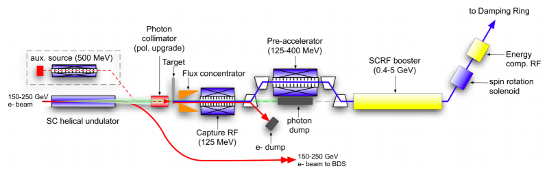
The degree of photon polarization depends on the angular distribution of the photons. The intensity of the undulator radiation has the maximum around the beam axis. By cutting the outer part of the radial symmetric photon beam with a collimator, the positron polarization is increased by contemporaneous decreasing the positron yield. The yield of 1.5 e+/e- can be recovered by increasing the active length of the undulator and choosing . Table 1 illustrates the relation between undulator-K values, collimator aperture, active length of the undulator and expected degree of positron beam polarization using a flux concentrator as optical matching device with parameters described in the TDR [1]. Depending on the electron beam energy and the K value, the positron polarization approaches 29% for mm up to 50-60% if the photon beam radii are collimated to mm (see also [4] and table 4).
| parameter | unit | GeV | |||
|---|---|---|---|---|---|
| [GeV] | 250 | ||||
| K value | 0.45 | 0.92 | |||
| undulator length | [m] | 147 | 49 | 70 | 143.5 |
| collimator iris radius | [mm] | 1.4 | 1.0 | 0.7 | |
| power absorption | [kW] | 13 | 43 | 132 | |
| [%] | 30 | 37 | 50 | 59 | |
Since the positron yield decreases with decreasing electron beam energy, the so-called 10 Hz scheme has been proposed for centre-of-mass energies below 300 GeV. It explores a 5 Hz electron beam for physics alternating with another 5 Hz electron beam of 150 GeV to create the photons and subsequently the positrons. Current studies [5] show that also at low energies the electron beam could create enough photons to achieve the desired luminosity and 30% positron polarization. An upgrade to 40% is possible. However, a higher degree of polarization would require the 10 Hz scheme. The study in this paper is aimed for degrees of positron polarization of 50% and higher. Therefore, for GeV the 10 Hz scheme has been considered.
Some facts complicate the design of the photon collimator:
-
•
The opening angle of the radiated photon beam is determined by the energy of the electron beam; it is proportional to . Although the helical undulator is located at a distance of 400 m upstream the positron target, the photon beam spot is small. The energy deposition density along the path of the intense photon beam is large in the collimator and the positron target. The conversion target is designed as spinning wheel, so the thermal load is substantially reduced. The photon collimator is fixed, static and it has to stand a huge power absorption. Depending on the electron beam energy and the desired positron polarization, the average photon beam power is in the range of kW (see also table 4).
-
•
Since the positron source is located at the end of the main linac, its parameters are strongly coupled to the centre-of-mass energy of the collider. This also applies to the photon collimator. It is impossible to cover with one design the requirements for all centre-of-mass energies.
3 ILC photon collimator system
Three important energies are considered for running the ILC:
-
•
GeV to produce Higgs bosons, mainly by the Higgs-Strahlungs process,
-
•
GeV to study the threshold of top-quark pair production,
-
•
GeV, the nominal energy to study interesting processes of the Standard Model and beyond.
For the baseline option, the undulator parameters are adjusted to get a positron beam which is 22% up to about 30% polarized. With a photon collimator the positron polarization can be increased: The aperture of the collimator determines the average polarization of the photon beam at the target and hence, of the positrons produced and captured.
To achieve flexibility in polarization and yield manipulation for the positron beam which is coupled to the energy of the electron beam, a system of three collimators with attenuating apertures is proposed. To increase the positron polarization up to 50-60%, at GeV only the first collimator is needed, at GeV the first and second collimators and at GeV all three collimators are used.
In the past, several possibilities for a collimator design were discussed [6, 7] but a flexible design suitable for different centre-of-mass energies was not considered in detail. All collimator designs have to deal with the intense, focused photon beam. Simple, adjustable spoilers in front of the absorber material are less effective for a photon than for an electron beam.
The collimator design described here consists of stationary parts, ı.e. the collimator material is not moved to distribute the heat load over a larger volume. A collimator system with moving (rotating) components is also possible and currently under consideration.
In order to choose material and dimensions of the collimator, the electromagnetic shower distribution and the corresponding energy deposition in the material has to be considered.
3.1 Electromagnetic shower in the collimator
The energy of the undulator photons (first harmonic) is few MeV up to few tens MeV depending on the drive electron beam energy, the opening angle of the photon beam is proportional to . The photon collimator should absorb the outer part of the photon beam. At high energies, the characteristic interaction length of photons is given by the radiation length . In principle, a high Z-material with large density and small radiation length would convert the photons and stop the remaining particles best so that the collimator could be quite compact. However, a shorter radiation length corresponds to a higher pair-production cross section, and so the density of the produced shower particles, ı.e. e+e- pairs and Bremsstrahlungs photons, is enhanced and the energy deposition density increases. That means that the temperature rise could be too large in the critical region at and near the inner surface of the collimator.
To choose a reliable design of the collimator, the passage of the photon beam through the collimator material has been simulated. The dimension and shape of the collimator as well as the material were adjusted by keeping the temperature rise along z-direction at an acceptable, relatively constant level, e.g. to avoid sharp temperature jumps. This reduces the stress in the collimator material and prevents overloading.
3.2 Basic collimator layout
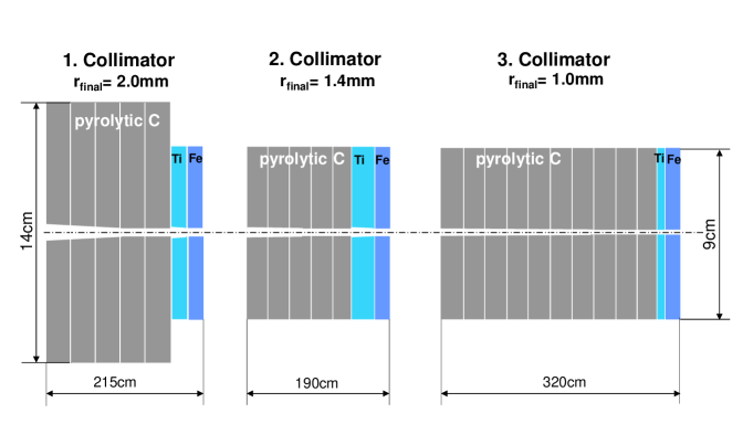
The collimator design suggested consists of three parts; the minimal aperture radii are 2 mm, 1.4 mm and 1.0 mm for the first, second and third collimator. With the first collimator the polarization is increased up to 50% for electron beam energies of 150 GeV (GeV). The first and the second or all three collimators are necessary to achieve positron polarization above 50% for centre-of-mass energies of GeV or GeV, respectively.
The energy deposition in the collimator has been calculated using the FLUKA Monte Carlo code for particle tracking and particle interactions with matter [8]. By means of this simulation tool the optimization of the photon collimator design is done by quantifying the heat load in the collimator and selecting the material corresponding to the tolerable thermo-mechanical stress. The temperature rise, , is described by
| (1) |
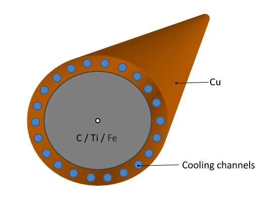
where is the energy deposition in the material, the mass and is the specific heat capacity. The volume elements with highest energy deposition, the so-called peak energy deposition density (PEDD), experience the maximal temperature rise. The collimator design has to avoid PEDD values which could damage the material and cause failure of the collimator. The results of calculations and simulations resulted in a system which is sketched in figure 2 and presented in the following sections.
3.2.1 Collimator material
The main fraction of energy is absorbed in the first part of each collimator stage. A low-Z material, pyrolytic graphite, has been chosen. Its evaporation point scores up to 3650∘C without a liquid phase [9]. In addition,pyrolytic graphite is very resistant against particle evaporation by energy impact. The material is strong anisotropic in the (xy) plane (basal direction) and in (z) direction; the thermal conductivity is a factor of 200 higher in the basal direction and has a very low thermal expansion coefficient [10]. However, due to the high radiation length of cm, a very long collimator is needed to absorb the whole unwanted part of the photon beam. In order to distribute the energy deposition in the collimator material and to keep the collimator as short as possible, proper medium-Z (or high-Z) material with smaller radiation length has to follow the graphite segments. Titanium alloy (Ti8Mn) and iron (St-70) have been chosen as collimator material behind the pyrolytic graphite parts.
| parameter | unit | pyr. C | Ti8Mn | Iron (St-70) | |
| (x,y) | (z) | ||||
| density | g/cm3 | 2.2 | 4.7 | 7.9 | |
| specific heat capacity | J/ | 0.837 | 0.495 | 0.434 | |
| thermal conductivity | W/ | 346 | 1.73 | 11–16 | 61 |
| coeff. of thermal expansion | 0.5 | 6.5 | 10 | 12 | |
| critical energy | MeV | 81.7 | 26.0 | 21.8 | |
| radiation length | cm | 19.32 | 3.56 | 1.76 | |
| melting point | K | 3900 | 1565 | 1870 | |
| (sublimation) | |||||
| modulus of elasticity | GPa | 20 | 115 | 200 | |
| Poisson’s ratio | 0.3 | 0.33 | 0.3 | ||
| ultimate tensile strength | MPa | 90 | 900 | 700 | |
| tensile strength (yield) | MPa | 90 | 810 | 340 | |
| fatigue strength | MPa | 280 | |||
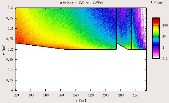
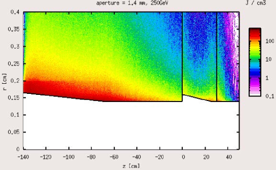
Figure 3 shows the simulated energy deposition distributions in all three collimator stages assuming a 250 GeV electron beam to achieve 50% positron polarization. It is clearly visible that the collimator design allows a quite uniform temperature distribution along the collimator aperture.
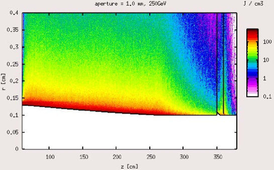
It should be remarked that for the simulations the collimator segments are assumed as simple, one-piece blocks. The fabrication of such segments with small aperture including cooling channels has not been regarded; most likely the longer collimator components will consist of partitioned segments. The proper alignment of the collimators with small aperture segments requires special care to obtain the desired reproducibility of polarization.
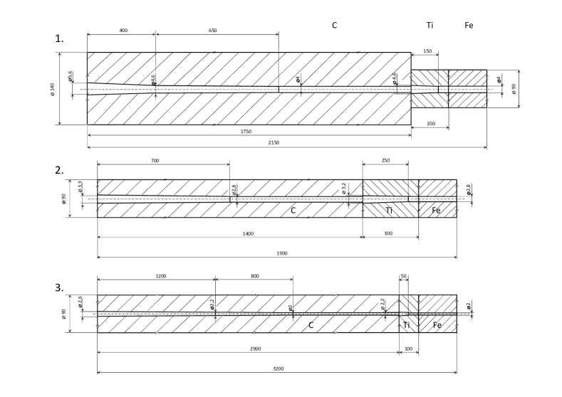
3.2.2 Dimensions of the first, second and third collimator
The lengths of the collimator parts are optimized to lower the energy deposited in the following higher Z material to an acceptable level. Since the average energy of the photons is below or near the critical energy of the collimator material, the highest temperatures occur at and near the inner surface. In order to distribute the load over a larger volume in the collimator material, slightly tapered sections are inserted at the beginning of the graphite and titanium parts. In case of the first and third collimator (2 mm and 1 mm final iris radius), the graphite part is tapered in two steps (see table 3). In the iron part the aperture is not tapered.
At higher centre-of-mass energies smaller collimator apertures are required to achieve high positron polarization. Since the photon cut-off energy increases with the squared energy of the electrons passing the undulator, also a longer collimator is required to stop the photons. In particular, the pyrolytic part must be longer to protect the following titanium and iron sections.
The dimension given in table 3 and shown in figure 4 represent the suggested collimator design. It allows to achieve almost 60% positron polarization at GeV and 50% at GeV. In addition, the study included the possibility to achieve 60% positron polarization at GeV. In this case all apertures of each collimator was reduced by 0.3 mm keeping length and outer diameter as given in table 3; However, in this case the power dumped in the photon collimator would be almost three times as much as in the case of 50% positron polarization (see also table 4).
| 1. collimator | 2. collimator | 3. collimator | |||||||
| final | |||||||||
| iris radius | 2 mm | 1.4 mm | 1 mm | ||||||
| length | out. rad. | weight | length | out. rad. | weight | length | out. rad. | weight | |
| [mm] | [mm] | [kg] | [mm] | [mm] | [kg] | [mm] | [mm] | [kg] | |
| pyr. C | 1,750 | 70 | 72.7 | 1,400 | 45 | 31.2 | 2,900 | 45 | 64.6 |
| Ti8Mn | 200 | 45 | 5.7 | 300 | 45 | 8.6 | 100 | 45 | 2.9 |
| Iron | 200 | 45 | 10 | 200 | 45 | 10 | 200 | 45 | 10 |
| active length | 2,150 | 1,900 | 3,200 | ||||||
| taper | |||||||||
| parameters | |||||||||
| length | length | length | |||||||
| [mm] | [mm / mm] | [mm] | [mm / mm] | [mm] | [mm / mm] | ||||
| pyr. C | 400 | 2.9 / 2.3 | 700 | 1.65 / 1.4 | 120 | 1.3 / 1.1 | |||
| 650 | 2.3 / 2.0 | 800 | 1.1 / 1.0 | ||||||
| Ti8Mn | 150 | 2.3 / 2.0 | 250 | 1.60 / 1.4 | 50 | 1.1 / 1.0 | |||
The collimator absorbs more than 99.9% of the unwanted part of the photon beam and the secondary particles; less than 0.1% reaches the positron production target.
4 Thermal load and cooling of the collimator
The average power and the peak energy deposited in the collimator, and , as well as the absorbed power have been simulated with FLUKA and ANSYS. They are summarized in table 4 for the different centre-of-mass energies and degrees of positron polarization. These values are used to calculate the requirements for the cooling system and to evaluate the thermo-mechanical load in the collimator. The numbers in table 4 figure out that about half of the photon beam power is dumped in the collimator to get 50% positron polarization. In order to reach 60% positron polarization at GeV, the power absorption rises to 75% with a final collimator iris radius of 0.7 mm.
| photon collimator parameters | cms energy [GeV] | |||||||||
| 250 | 350 | 500 | 500 (high lumi) | |||||||
| electron beam energy | [GeV] | 150 | 125 | 178 | 253 | 253 | ||||
| repetition rate | [Hz] | 5 | 5 | 5 | ||||||
| number of e+ bunches | 1312 | 2625 | ||||||||
| active undulator length | [m] | 231 | 192.5 | 196 | 70 | 70 | 143.5 | |||
| photons / train | [x 1015] | 11.8 | 9.8 | 10.0 | 3.6 | 7.2 | 14.6 | |||
| average photon power | [kW] | 98.5 | 68.4 | 113.6 | 82.9 | 166.2 | 339.5 | |||
| 1st harmonic cut-off | [MeV] | 10.1 | 7.0 | 14.2 | 28.6 | |||||
| final iris radius | [mm] | 2.0 | 2.0 | 1.4 | 1.0 | 1.0 | 0.7 | |||
| e+ polarization | [%] | 55.3 | 58.5 | 50.3 | 50.3 | 58.7 | ||||
| transversal mismatch | 0 | 100 | 0 | 100 | ||||||
| absorbed power in collimator | [kW] | 48.5 | 42.4 | 68.7 | 43.5 | 87 | 87.3 | 254.8 | 255 | |
| 1. collimator | final iris radius mm | 1.7 mm | ||||||||
| Pyr. C: | [J/g] | 53 | 45 | 53 | 13 | 26 | 33 | 99 | 129 | |
| [K] | 63 | 54 | 63 | 16 | 31 | 39 | 118 | 154 | ||
| [kW] | 45.2 | 40 | 36.3 | 7.9 | 15.8 | 16.0 | 52.8 | 53.2 | ||
| Ti: | [J/g] | 10 | 5 | 10 | 2 | 5 | 10 | 23 | 39 | |
| [K] | 20 | 10 | 20 | 4 | 10 | 20 | 46 | 79 | ||
| [kW] | 0.6 | 0.3 | 0.8 | 0.2 | 0.4 | 0.4 | 2.0 | 2.0 | ||
| Fe: | [J/g] | 7 | 4 | 7 | 2 | 4 | 7 | 18 | 28 | |
| [K] | 16 | 9 | 16 | 5 | 9 | 16 | 42 | 65 | ||
| [kW] | 0.3 | 0.1 | 0.3 | 0.1 | 0.2 | 0.2 | 0.9 | 0.8 | ||
| Cu: | [kW] | 2.4 | 2.0 | 1.9 | 0.4 | 0.8 | 0.8 | 2.8 | 2.9 | |
| 2. collimator | final iris radius mm | 1.1 mm | ||||||||
| Pyr. C: | [J/g] | 104 | 40 | 81 | 100 | 318 | 408 | |||
| [K] | 124 | 49 | 97 | 119 | 380 | 488 | ||||
| [kW] | 25.9 | 12.9 | 25.8 | 26.0 | 82.6 | 83.1 | ||||
| Ti: | [J/g] | 15 | 9 | 18 | 26 | 72 | 98 | |||
| [K] | 30 | 18 | 36 | 53 | 145 | 198 | ||||
| [kW] | 0.9 | 0.6 | 1.2 | 1.2 | 4.1 | 4.1 | ||||
| Fe: | [J/g] | 11 | 6 | 13 | 18 | 48 | 71 | |||
| [K] | 25 | 14 | 30 | 42 | 111 | 164 | ||||
| [kW] | 0.2 | 0.2 | 0.3 | 0.3 | 1.1 | 1.1 | ||||
| Cu: | [kW] | 2.3 | 1.2 | 2.4 | 2.5 | 8.2 | 8.2 | |||
| 3. collimator | final iris rad. 1 mm | 0.7 mm | ||||||||
| Pyr. C: | [J/g] | 47 | 95 | 120 | 325 | 377 | ||||
| [K] | 56 | 113 | 143 | 388 | 450 | |||||
| [kW] | 17.9 | 35.8 | 35.8 | 90.0 | 89.5 | |||||
| Ti: | [J/g] | 10 | 19 | 32 | 65 | 86 | ||||
| [K] | 20 | 38 | 64 | 131 | 174 | |||||
| [kW] | 0.1 | 0.3 | 0.3 | 0.6 | 0.6 | |||||
| Fe: | [J/g] | 7 | 15 | 24 | 50 | 63 | ||||
| [K] | 16 | 35 | 55 | 115 | 145 | |||||
| [kW] | 0.1 | 0.3 | 0.3 | 0.5 | 0.6 | |||||
| Cu: | [kW] | 1.8 | 3.7 | 3.7 | 9.2 | 9.1 | ||||
4.1 Collimator cooling system
In the equilibrium, the radial heat dissipation through a hollow cylinder with central heating is given by [14]
| (2) |
where and are the inner and outer radius of the cylinder, its length, and the thermal conductivity. Equation (2) is used to adjust the outer radius of the collimator and the cooling power required to achieve the average temperature difference between inner and outer surface of the cylinder. Assuming a homogeneous, radial directed thermal dissipation from the inner hot to the outer cooled surface, the required average cooling power corresponds to .
Due to the slightly conical apertures the maximum heat load is distributed and kept within reasonable limits. The time-dependent temperature rise and fall with each bunch train smears out in the bulk of the collimator since the heat transfer from the inner to the outer surface takes few seconds. The average heat flux through the outer surface of the collimator parts – mainly the graphite – is below 10 W/cm2.
For a technical solution of cooling the collimators are jacketed with copper, a material of high thermal conductivity. Straight cooling channels are embedded in 2 cm copper as shown in figure 5. Due to the dimension chosen for the collimator material graphite, titanium and iron, the photon beam is stopped in these material and only a small part of the shower tail reaches the copper layer. The total power deposited in the copper is listed in table 4.
The cooling water has to absorb the power given in equation (2);
| (3) |
where is the average difference between incoming and out-coming water temperature in the cooling tubes, and corresponds to the water flow needed to carry away . With cooling channels of radius one gets
| (4) |
which allows to determine the required velocity of the cooling water, ;
| (5) |
From equation 3 follows that a maximum water flow rate of about 4 l/s is required. Keeping the values of at about 1 to 2 m/s and using mm, 22 cooling channels should be placed into the copper jacket encasing the collimators with 9 cm diameter, and 32 cooling channels into the copper jacket encasing the collimators with 14 cm diameter. So the temperature of the cooling water is increased by about 5–10 K depending on and the required luminosity. The precise numbers for each collimator part can be calculated based on the energy deposition given in table 4 and using equation (8).
The Reynolds number,
| (6) |
is 11,430 for m/s indicating turbulent flow; is the kinematic viscosity. The parameter values of water used for these considerations are summarized in table 5.
| parameter | |||
|---|---|---|---|
| value | 4182 J/(kg K) | 0.9982 g/cm3 | 7.98437m2/s |
The heat flux from copper through the surface of water channels, , corresponds to
| (7) |
where is the heat transmission coefficient to the water and the length of the cooling channels. The design presented here requires values of between W/cm2/K and W/cm2/K for a water temperature drop of K.
More complex is the heat transfer from the collimator material, ı.e. graphite, titanium, iron, to the copper jacket. In particular, the graphite – copper connection is important.
The heat transfer depends strongly on the the surface roughness and the contact pressure. In reference [15] the heat transfer coefficient from graphite to copper is estimated depending on the contact pressure and the gas filling the gap at the material junction. Based on this considerations a transfer coefficient of W/cm2/K can be achieved. Taking into account the heat transfer from graphite to copper, the difference between the temperatures in copper at the cooling channels and the inner surface of the collimator is
| (8) |
with the thermal resistance
| (9) |
where is the aperture radius of the graphite part, the length, the contact C–Cu is located at , the outer radius of the graphite and the inner radius of the copper jacket, and is the effective outer radius of the copper at the cooling channels. With realistic values, W/cm2/K, the average temperature at the inner collimator surface increases by about 15% (60%) in comparison to the ideal case neglecting the thermal resistance at the Cu-C junction. This can be accepted since graphite stands substantially higher temperatures than the average temperatures of about 300–400∘C. At the Cu-Ti and Cu-Fe contacts, thermal transfer coefficients of 0.4 W/cm2/K increase the average temperature at the inner surface by about 10% for the iron and about 2% for the titanium part in comparison to the ideal case. Anyhow, the power deposition in the titanium and iron sections is relatively low. So the cooling of the whole collimator is not a problem.
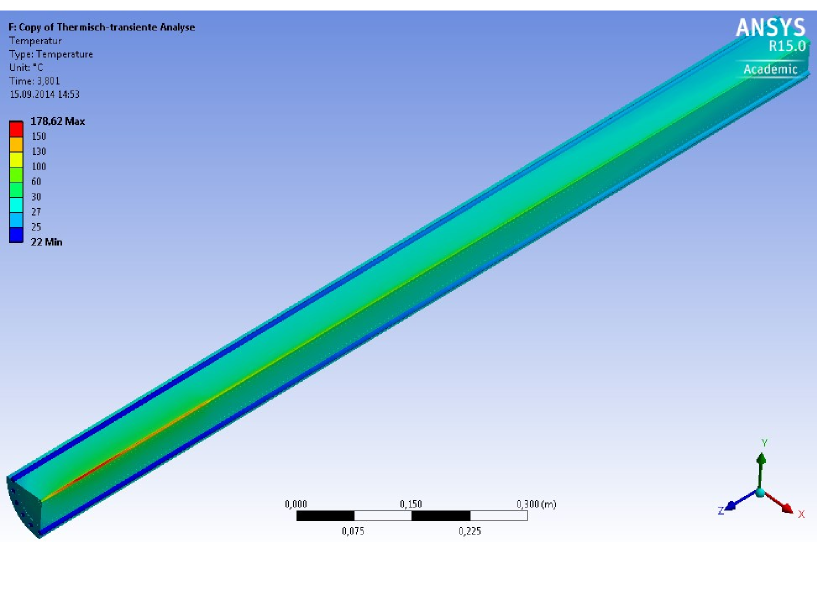
It must be remarked that the considerations of the cooling parameters are based on the stationary case and correspond to averaged numbers. Further, the temperature distribution is not homogeneous over the collimator, and the temperature of the cooling water depends on its path along the collimator. To get a real picture of the temperature distribution, ANSYS simulations have been performed taking into account the pulsed heating and a water flow of 1 l/s. The resulting temperature distribution for the pyrolytic graphite and the cooling water of the second collimator stage is shown in figure 6 for GeV; the temperature difference of the cooling water is 4.3 K.
5 Load and potential material degradation
5.1 Maximum heat load
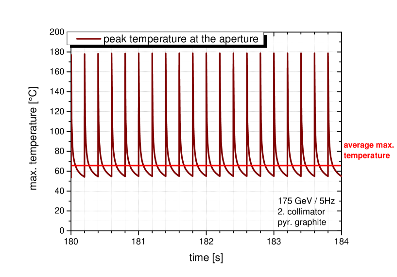
The bunch structure of the ILC beam yields a cyclic load of the collimator material. The maximum values are obtained at the innermost part of the collimator. In the chosen collimator design, the instantaneous heating of pyrolytic graphite by one bunch train reaches maximum values of about 124 K; the maximum heating by one bunch only is below 0.12 K. Since the heat dissipates, the values for the peak energy density and the corresponding maximum temperature rise due to bunch train are about 20% lower than the value expected by multiplying the number of bunches with the maximum temperature rise by one bunch. The effect of heat dissipation during one bunch train is even less important in the Ti and Fe parts of the collimator since the shower particles are spread to a wider region.
The peak energy deposition per bunch train, the corresponding maximum temperature as well as further important parameters of the power deposition in the collimator are summarized in table 4 for the different centre-of-mass energies and the collimator parts.
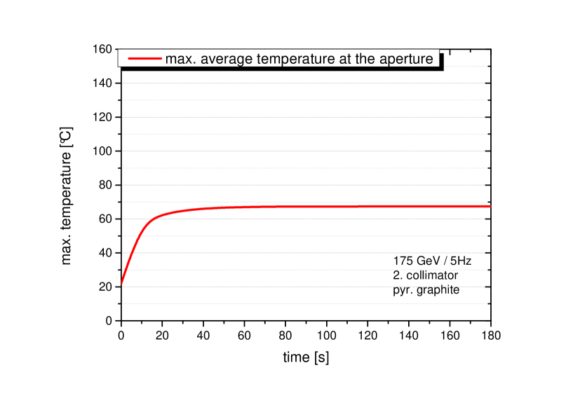
To illustrate the time-dependent temperature evolution over bunch trains, figure 7 shows the maximum temperature in the pyrolytic graphite part of the second collimator for GeV. After several bunch trains the average temperature is reached which is determined by the collimator dimension, the deposited energy and the cooling system (see also equation (2)).
5.2 Stress
The rapid energy deposition during one bunch train causes stress inside the collimator since the material is not able to expand as fast as it is heated. Assuming short, intense beam pulses, the irradiated zone is instantaneously heated under constant volume, leading to a change of pressure; ı.e. the material is in a hydrostatic state of stress. The corresponding thermo-elastic peak stress value is given by [16, 17]
| (10) |
where is the the temperature rise per bunch train; the Young’s modulus of elasticity, , the coefficient of thermal expansion, , and Poisson’s ratio, , can be taken from table 2. From the heated zone stress waves emanate. However, for the collimator design presented here the instantaneous temperature rise is too small to create dangerous stress waves in the material. For example, the highest instantaneous temperature rise in the pyrolytic graphite amounts to roughly 0.1 K per bunch yielding about 125 K per bunch train (1 ms). Since pyrolytic graphite is a highly anisotropic material with different Poisson’s ratio and thermal expansion in (x,y) and (z) direction, equation (10) cannot applied to estimate the peak stress in the graphite parts of the collimator. For the parameter values considered here, the maximum stress can be approximated with
| (11) |
The instantaneous maximum temperature rise of 125 K in the pyrolytic graphite results in peak stress of about 14 MPa.
It should be remarked that the material parameters depend on the temperature. The stress development depends strongly on the temperature, and equations (10) or (11) allow only a rough estimate.
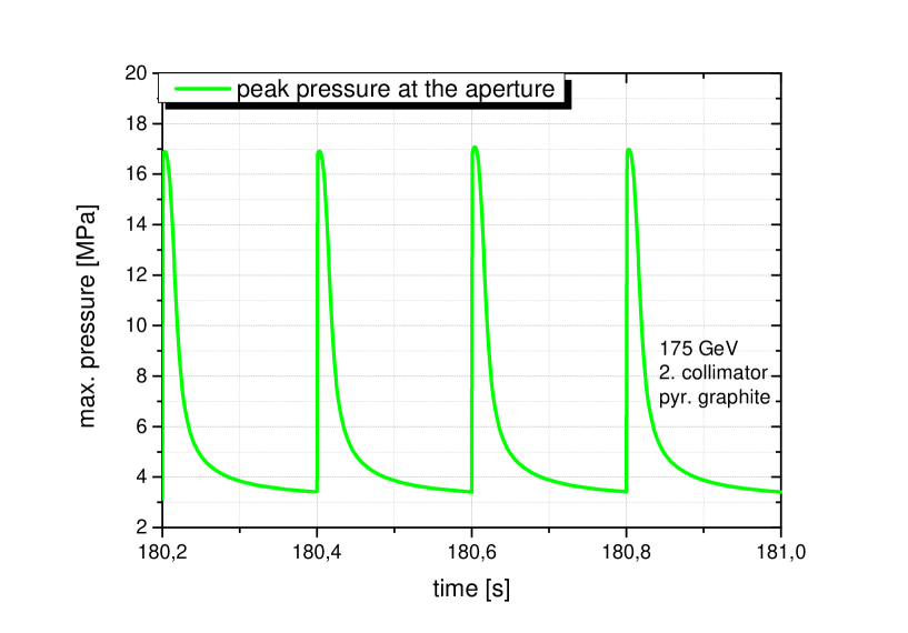
The peak stress values appear near the collimator aperture, in the hottest region. Since the material cannot expand during the short time of one bunch-train, pressure at the inner collimator surface is produced. The time evolution of the maximum pressure at the aperture in the pyrolytic graphite is visualized in figure 8 for the second collimator for GeV. Similar distributions have been calculated for all collimator parts and centre-of-mass energies. The gradient between the average temperatures of inner and outer collimator region causes a permanent static stress of few MPa.
The stress evolution is important to evaluate the load during long-term operation. Assuming a running time of 5,000 hours, the ILC collimator system undergoes load cycles. However, cyclic load could damage the material already at values substantially below the load limit: A rule of thumb gives about 40% of the tensile yield strength as fatigue limit. These limits are derived in tests with mechanical load. At the collimator, the impact of high-energy photons and secondary particles may change the properties of the material and reduce the fatigue limit further. In addition, all material parameters depend on the temperature. If for instance the thermal transfer coefficient is reduced due to long-term irradiation, the average temperature increases and the corresponding fatigue limit could decrease. Thus, it is necessary to have a good safety margin.
A comparison of the stress created per bunch train with the parameters given in table 2 indicates that the cyclic amplitude does not reach the fatigue limit allowed for the collimator material. However, in case of mm iris radius to achieve almost 60% polarization at GeV, the peak stress is increased by a factor 3 (up to 4) and comes close to or exceeds the fatigue limit.
5.3 Misalignment
For an ideally positioned photon beam the energy deposition in the collimator is below the fatigue pressure limit. However, already a transverse displacement of 100 m increases substantially the energy deposition in the collimator as shown in table 4 for the high luminosity option at GeV. For an iris with mm, the maximum values exceed neither the fatigue limit nor the yield strength. However, the safety margin is reduced.
5.4 Damage and deformation
Since the photon collimator is a dump for a large part of the photon beam, radiation damages of the collimator material must be taken into account. A rough measure of this damage is the displacement per atom (dpa). These dpa values were determined by FLUKA simulations for each collimator part. Table 6 summarizes the maximum dpa values induced for different centre-of-mass energies. Only at the region near the inner collimator surface these high values are obtained; dpa values decrease in radial direction corresponding to the energy deposition shown in figure 3.
| 125 GeV | 350 GeV | 500 GeV | ||
| 125 GeV | 150 GeV | 175 GeV | 250 GeV | |
| (1. collimator) | (1. collimator) | (2. collimator) | (3. collimator) | |
| pyr. C | ||||
| Ti8Mn | ||||
| Iron(St-70) | ||||
It is not easy to find a clear statement up to which dpa levels material can be explored and how the material properties change. In general, titanium alloys and iron should stand values up to 1 dpa and the highly affected zone is thin. Therefore, one year operation time is probably at the limit. It is recommended to test the material degradation in an experiment before fixing the final design.
Graphite shows depending on dpa value and temperature a substantial dimensional change as reported in references, e.g. [18, 19]. The review [20] describes the swelling and the change of parameters of pyrolytic graphite when irradiated by electrons. Depending on dpa and temperature, the material could expand in longitudinal and tighten in basal direction. At the photon collimator, this dimensional change would appear at the innermost layer after a longer time of irradiation. The size of the dimensional change depends on the temperature and dpa value and also on the special material.
At a first glance the expansion in longitudinal direction can be accepted since the pyrolytic collimators are made of slices which can be positioned in a safe distance. The expansion in basal direction yields a slight increase of the collimator aperture. This could affect the degree of positron polarization but taking into account the jitter and of a realistic beam, this effect should be negligible. Another problem could arise concerning the stored energy release of irradiated graphite. Following reference [21], that the amounts of stored energy would be small.
Nevertheless, these problems need further studies; in particular concerning long-term stability in case of misalignment.
5.5 Activation
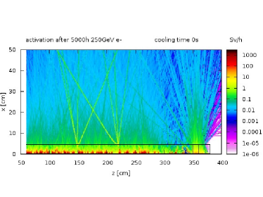
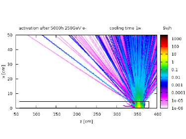
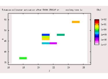
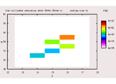
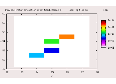
The collimator material is exposed to a high radiation dose and nuclear reactions are triggered. The activation induced by the photon beam and the secondary particles including neutrons has been calculated using the FLUKA Monte Carlo code for particle tracking and particle interactions with matter [8]. In figure 9, the equivalent dose after 5000 hours operation is shown up to a radial distance of 0.5 m for the third collimator at GeV. After one week cooling time only the long-living nuclei contribute to the equivalent dose. The highest dose comes from the aperture of the Ti8Mn part; at a distance of 0.5 m the equivalent dose amounts roughly 30 mSv/h. Following the half-life values given in table 7, this value reduces only slowly. Therefore, the activated components must be handled with special care.
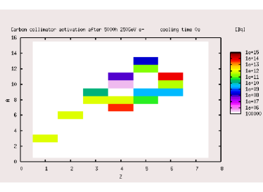
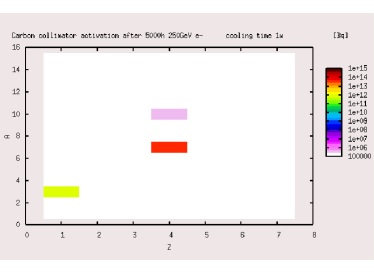
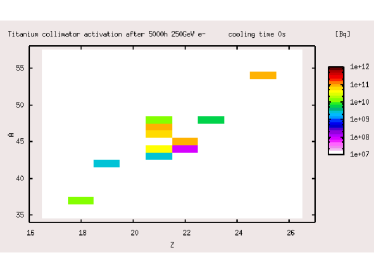
To illustrate the activation in the collimator, figure 10 shows the the isotopes given by the atomic number and the atomic weight and the decay rates after 5000 hours irradiation and after one week cooling time.
|
 |
 |
 |
 |
 |
 |
 |
In table 7 the nuclei with significant activity produced in the collimator material are listed.
| pyrolytic graphite | |||
|---|---|---|---|
| nucleus | half-life period | activation after 0 s [Bq] | activation after 1 w [Bq] |
| 12.33 y | |||
| 53.3 d | |||
| y | |||
| 20.39 min | - | ||
| Ti8Mn | |||
| nucleus | half-life period | activity after 0 s [Bq] | activity after 1 w [Bq] |
| 12.33 y | |||
| 35.04 d | |||
| 269 y | |||
| 21.5 s | - | ||
| 4.54 d | |||
| 58.6 h / 3.93 h | |||
| 83.79 d | |||
| 3.35 d | |||
| 43.67 h | |||
| 49 y | |||
| 15.97 d | |||
| 312.12 d | |||
| Fe (St-70) | |||
| nucleus | half-life period | activity after 0 s [Bq] | activity after 1 w [Bq] |
| 27.70 d | |||
| 5.59 d | |||
| 8.51 min | - | ||
| 312.12 d | |||
| 2.73 y | |||
6 Alternative collimator design
The photon collimator design presented here has disadvantages, in particular the use of pyrolytic graphite and the long extension. So it is worth to think about alternative design possibilities.
An obvious idea would be to replace at least a large part of the pyrolytic graphite by another material, for instance tungsten. The radiation length of tungsten is a factor 50 smaller than that of graphite, and tungsten resists very high temperatures. However, for the ILC undulator and the given energy of the electron drive beam, the particle multiplication in the electromagnetic shower causes large peak energy deposition. For tungsten the critical energy, ı.e. the threshold that Bremsstrahlung and pair-production dominates the ionization process, is much lower than for graphite (MeV, MeV) and it is below the energy of the photons. The shower created in tungsten causes a load which exceeds the recommended limits. This cannot be avoided by tapered apertures as done for design of the graphite parts: Due to the relatively low critical energy, the shower maximum in tungsten –and thus the energy deposition maximum– is about radiation length in the bulk while in graphite the maximum energy deposition is at/near the surface.
A better idea is to create a collimator design with rotating spoilers alternating with absorber material to stop the outer part of the photon beam. Such design is currently under consideration and development [22].
In another idea the collimator is integrated in the positron target design: A high Z material (large pair production cross section) is used for the conversion target and embedded in a low Z material (lower pair production cross section). The geometrical dimension, ı.e. the height, of this high-Z target material can be chosen such that it corresponds to the required aperture of a photon collimator. Considering a spinning target, such principal design provides photon beam collimation in y-direction. In order to collimate also in x-direction, jaws can be added in front of the target entrance. The jaws could be moved (up-down) to avoid thermal overload. The idea of such system is illustrated in [22]. Further studies are necessary to evaluate whether this scheme could be realized. But first rough simulations show that already the clever choice of the height of the converter target material increases the positron polarization. Table 8 gives an overview of the positron polarization which could be achieved.
| [GeV] | 250 | 350 | 500 | |
|---|---|---|---|---|
| [GeV] | 125 | 175 | 250 | |
| target height | [mm] | 4 | 2.8 | 2 |
| (target only) | [%] | 37 | 41 | 32 |
| (targetjaws) | [%] | – | 60 | 47 |
7 Summary
A high degree of positron polarization is desired for physics studies and can be achieved by collimating the undulator photon beam. Due to the close correlation between energy of the electron beam which passes the helical undulator, photon beam intensity, collimator iris and degree of polarization, the photon collimator system must be flexible. Further, it has to withstand huge heat loads without breakdown during a long operation time.
The multistage collimator design presented in this paper represents a solution to collimate the photon beam at the ILC positron source. For centre-of-mass energies up to 500 GeV, the material loads stay within acceptable limits taking into account an additionally safety margin against failure due to fatigue stress. Depending on the centre-of-mass energy, one, two or all three stages are used to collimate the photon beam. The system is water-cooled, the principal parameters of the cooling system are given. The presented solution can be adopted to electron beam energies up to 500 GeV. However, further simulation studies are recommended to optimize the design taking into account the special material properties as swelling of pyrolytic graphite or potential change of properties of the material due to long-term irradiation. This will further improve the reliability of the final design.
References
- [1] C. Adolphsen et al., The International Linear Collider Technical Design Report - Volume 3.I: Accelerator & in the Technical Design Phase, arXiv:1306.6353 [physics.acc-ph]; C. Adolphsen et al., The International Linear Collider Technical Design Report - Volume 3.II: Accelerator Baseline Design, arXiv:1306.6328 [physics.acc-ph].
- [2] V. E. Balakin and A. A. Mikhailichenko, Conversion system for obtaining highly polarized electrons and positrons, INP-79-85.
-
[3]
G. Alexander et al.,
Nucl. Instrum. Meth. A 610 (2009) 451,
[arXiv:0905.3066 [physics.ins-det]];
G. Alexander et al., Phys. Rev. Lett. 100 (2008) 210801. - [4] A. Ushakov et al., Production of highly polarized positron beams, Proc. IPAC, San Sebastian, Spain (2011), 997.
- [5] A. Ushakov et al., Simulations of the ILC positron source with 120 GeV electron drive beam, LC Note LC-REP-2013-019.
- [6] A. A. Mikhailichenko, Collimators for ILC, Conf. Proc. C 060626, 807 (2006).
- [7] L. Zang, A. Wolski, I. Bailey, High Power Photon Collimators for the ILC, Proceedings of PAC09, Vancouver, BC, Canada, 2009; https://accelconf.web.cern.ch/accelconf/PAC2009/papers/mo6rfp093.pdf
- [8] FLUKA web site, http://www.fluka.org/fluka.php
- [9] J. Pappis and S.L. Blum, Properties of Pyrolytic Graphite, J. Am. Cer. Soc. 44(1961)592.
- [10] D. Yao and B. Kim, Applied Thermal Engineering 23, (2003) 341-352.
- [11] MatWeb Material Property Data, http://www.matweb.com/
- [12] Dubbel, Taschenbuch für den Maschinenbau, 17. Aufl., Springer-Verlag, 1990.
- [13] Particle Data Group, Atomic and Nuclear Properties of Materials http://pdg.lbl.gov/2014/AtomicNuclearProperties/index.html
- [14] W. Wagner, Wärmeübertragung, 3. überarb. Aufl., Vogel Buchverlag, 1991.
- [15] M. Maslov, M. Schmitz, V. Sychev, Layout Considerations on the 25GeV / 300kW Beam Dump of the XFEL Project, TESLA-FEL 2006-05, DESY, August 2006.
- [16] P. Sievers, Elastic Stress Waves in Matter Due to Rapid Heating by an Intense High-Energy Particle Beam, CERN LAB II/BT/74-2.
- [17] S.P. Timoshenko and J.N. Goodier, Theory of Elasticity, 3rd edition, McGraw-Hill, Inc., New York, 1970.
- [18] N. Simos, H. G. Kirk and K. T. McDonald, Experimental Study of Radiation Damage in Carbon Composites and Graphite Considered as Targets in the Neutrino Super Beam, Conf. Proc. C 0806233 (2008) MOPC093.
- [19] B. J. Marsden (Editor), Irradiation Damage in Graphite Due to Fast Neutrons in Fission and Fusion Systems, IAEA-TECDOC-1154, September 2000.
- [20] J. Koike and G.F. Pedraza, J. Mater. Res., 9 (1994) 1899.
- [21] N.C. Gallego, T.D. Burchell, A Review of Stored Energy Release of Irradiated Graphite, Oak Ridge National Laboratory, ORNL/TM-2011/378.
- [22] S. Riemann, P. Sievers, A. Ushakov, Status of target and photon collimator work for polarized positrons, talk given at the International Workshop on Future Linear Colliders (LCWS14), Belgrade, Serbia, October 2014.