Multi-Branch Lattice-Reduction SIC for Multiuser MIMO Systems
Abstract
In this paper, we propose a new detection technique for multiuser multiple-input multiple-output (MU-MIMO) systems. The proposed scheme combines a lattice reduction (LR) transformation, which makes the channel matrix nearly orthogonal, and then employs a multi-branch (MB) technique with successive interference cancellation (SIC). A single LR transformation is required for the receive filters of all branches in the scheme, which proposes a different ordering for each branch and generates a list of detection candidates. The best vector of estimated symbols is chosen according to the maximum likelihood (ML) selection criterion. Simulation results show that the proposed detection structure has a near-optimal performance while the computational complexity is much lower than that of the ML detector.
Index Terms:
Multiuser MIMO systems, lattice reduction, multi-branch detection, successive interference cancellation.I Introduction
Multi-input multi-output (MIMO) systems are key to increasing the spectral efficiency of wireless communication systems, which makes high data rates transmission possible [1]. Despite its advantages, MIMO suffers from interference between multiple antennas and, in multiuser scenarios, is affected by the multiuser interference. To ensure the viability of MIMO systems it is necessary to develop efficient detection techniques with low computational complexity. In this direction many detectors have been proposed in the last decade or so, see, e.g., [2]–[6]. In [7] the complex lattice reduction (LR) was proposed to improve the performance of MIMO detection techniques. The complex LR transformation finds a new basis for the channel matrix, which is nearly orthogonal allowing a more effective detection. The ordered successive interference cancellation (OSIC) [8] can offer a good performance when combined with other detection schemes. The lattice reduction successive interference cancellation (LR-SIC) has been developed in [9],[10],[11],[12], [13]. The works in [14] and [15] proposed a novel successive interference cancellation (SIC) strategy for communications systems based on multiple branches (MB). Although LR-based detectors can attain the full receive diversity, a key problem with these detectors [2]–[6] is that the performance gap to the ML detector increases with the system size and the modulation order.
In this work we propose a new detection scheme for multiuser MIMO (MU-MIMO) systems in the uplink scenario that combines LR, SIC and MB schemes to devise an MB-LR-SIC detector and which obtains a near-ML performance. The main idea is to employ an LR transformation in the channel matrix, then generate multiples branches, where each branch has a different ordering pattern and produces different symbol estimate vectors using the LR-SIC structure. In particular, the first branch employs a column-norm based ordering in the LR domain and the remaining branches use shifted versions of the order of the first branch. The branch with the best performance among the list of candidates is selected using the ML criterion. We study the performance of the proposed and existing algorithms using a realistic MU-MIMO scenario with path loss, log-normal shadowing and multiple antennas per user. We also assess the performance of the proposed MB-LR-SIC detector with practical channel estimation algorithms and compare with with several existing detectors. Simulation results show that the system performance with the proposed MB-LR-SIC detector approaches the optimal ML detector.
This paper is structured as follows. Section II examines the basic concepts for multiuser MIMO system. The proposed MB-LR-SIC detection scheme is detailed in Section III. Section IV is dedicated to the presentation and discussion of the numerical results obtained via computer simulations. Section V summarizes the conclusions.
II System Model and Existing Techniques
In this section, the basic concepts for multiuser MIMO systems are studied, starting with the mathematical representation of MU-MIMO systems and then a channel estimation technique for MIMO channels is described. We also review two important detection techniques, namely, complex lattice reduction SIC and multi-branch SIC.
II-A System Model
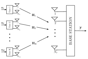
We consider the uplink of a multiuser MIMO system, as depicted in Fig. 1, with active users, antennas at the -th mobile station (MS), and antennas at the base station (BS), where . The received signal vector at BS is given by
| (1) |
where is the transmitted signal vector by the -th user taken from a modulation constellation , each symbol is carrying bits and . is the channel matrix of the -th user with elements correspond to the complex channel gains from the -th transmit antenna to the -th receive antenna. The vector is an zero mean complex circular symmetric Gaussian noise vector with covariance matrix , where and represents the expected value and Hermitian operator respectively. The expression in (1) can be written more conveniently as
| (2) |
where and , denotes transpose operator. The symbol vector of all users has zero mean and a covariance matrix , where is the signal power.
II-B MIMO Channel Estimation
In this paper the LS channel estimation algorithm for MIMO system proposed in [16] is used. In LS algorithm the cost function in the time instant must be defined based on a weighted average of error squares as
| (3) |
where and are the received and transmitted symbol vectors in the time instant , respectively, is the forgetting factor, is the channel matrix estimate in the time instant . The cost function is minimized by solving , where denotes the zero matrix. The LS estimation of channel matrix can be solved easily as
| (4) |
where can be iteratively calculated by
| (5) |
The matrix can be calculated iteratively by using the matrix inversion lemma as
| (6) |
Initially, we set the parameters and where is a small constant [17],[18],[19].
II-C Complex Lattice Reduction SIC Algorithm
The complex lattice reduction scheme finds a new basis which is shorter and nearly orthogonal compared to the original matrix , where is a uni-modular matrix (=1) and all elements of are Gaussian integers, i.e. . Linear detectors such as Zero Forcing (ZF) or minimum mean square error (MMSE) can be developed on the LR transformed channel matrix . Then satisfactory results have been obtained due to reduced noise enhancement obtained with [9],[20],[21].
With the channel matrix in the LR domain, and the definition of , the received signal vector in (2) can be rewritten as
| (7) |
Even though is nearly orthogonal, mutual interference between the components of the transformed signal is still present. For this reason SIC techniques in the LR domain results in additional improvements. The LR-SIC receiver consists of a bank of linear detectors based on the matrix , each detects a selected component of . The component obtained by the first detector is used to reconstruct the corresponding signal vector which is then subtracted from the received signal to further reduce the interference in the input to the next linear receive filter:
| (8) |
The estimate of is obtained after shifting and scaling operations [22] in the output of the -th linear detector , it is necessary to introduce re-scaling and re-shifting operations over the symbols, obtained by
| (9) |
where is a vector of ones, for all M-QAM modulation, denotes the rounding operator and is the -th row of . The index of depends on the selected order in which the interference vectors are subtracted. Then a new is calculated
| (10) |
where . The second linear detector uses the matrix , and the process is repeated times until all components of the estimated vector are found. Finally, the estimated transmit signal vector in the constellation domain can then be obtained by
| (11) |
The main steps to find and with CLLL reduction algorithm are described in [7].
II-D Multi-Branch SIC Detection
In the multi-branch scheme different orderings are explored for SIC, each ordering is referred to as a branch, so that a detector with branches produces a set of estimated vectors. Each branch uses a column permutation matrix . The estimate of the signal vector of branch , , is obtained using a SIC receiver based on a new channel matrix . The order of the estimated symbols is rearranged to the original order by
| (12) |
A higher detection diversity can be obtained by selecting the most likely symbol vector based on the ML selection rule.
III Proposed Multi-Branch Lattice Reduction SIC Detection
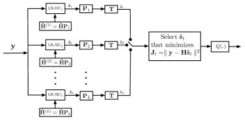
This section describes the proposed MB-LR-SIC detection scheme that combines the concepts previously presented. A schematic of the detector is shown in Fig. 2. The proposed detection structure employs an LR transformation in the channel matrix as in (7). Let be a column permutation matrix. Then the signal term in (7) can be expressed as
| (13) |
where is a column permutated version of and
| (14) |
In the proposed scheme, the -th branch () of the receiver employs an LR-SIC detector, as described in Section II-C, based on the permutated matrix to generate an estimate of . Then, the th branch transmitted signal candidate is obtained by
| (15) |
The best candidate out of the estimated data signal vectors is selected using the ML criterion, that is
| (16) |
In order to guarantee that a good candidate is always present in the set of the candidates generated, one of the branches (e.g. ) should implement a performance effective ordering (e.g. column-norm based ordering) in the LR domain. Here, the remaining branches used the so called Pre-Stored Patterns (PSP) proposed in [15]. The PSP can be described mathematically by
| (17) |
where denotes -dimensional matrix full of zeros, the operator rotates the elements of the argument matrix column-wise such that an identity matrix becomes a matrix with ones in the reverse diagonal. The PSP algorithm shifts the ordering of the cancellation according to shifts given by
| (18) |
where is the number of parallel branches and rounds the argument to the lowest integer according to the -th branch.
The description of the proposed MB-LR-SIC detection structure is depicted in Algorithm 1.
Initialization:
% CLLL in [7], input , output and
Do for to % Multi-Branch loop
if
% column-norm based ordering in
else
% Pre-Stored Patterns
end if
Do for to
% MMSE linear equalizer
% Shifting and Scaling operations [22]
End
End
The proposed scheme increases the chances of obtaining more reliable candidates for the transmitted data symbol vector. The MB-LR-SIC scheme shows a high diversity gain and can deliver a performance very close to the optimal ML detector.
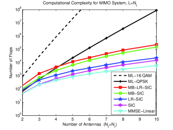
III-A Computational complexity
In this subsection, the computational complexity of the MB-LR-SIC is evaluated. Since the LR transformation requires the counting of floating points (flops) to know its computational cost, we have computed the number of flops per received vector using the Lightspeed Matlab toolbox [23]. In Fig. 3 it is shown the computational complexity for the different detection algorithms studied in this work. The figure compares the required number of flops versus the number of antennas for . For the ML detector, we have considered QPSK and 16-QAM modulation, whereas for the other detectors we have used only QPSK modulation due to the fact that the computational cost in these detectors does not vary significantly with the modulation type. The proposed MB-LR-SIC has a lower complexity than the ML detector and, as will be shown in the next section, the performance is very close to the ML detector.
IV Numerical Results
In this section, the performance of the proposed MB-LR-SIC scheme is compared with existing detection algorithms, which include the standard SIC, LR-SIC, MB-SIC and ML. We consider the uplink of a MU-MIMO system with active users. Two scenarios for the channels associated with each active user are considered. In the first scenario, we consider independent and identically distributed random fading channel models whose coefficients are complex Gaussian random variables with zero mean and unit variance. In the second scenario we consider a more realistic channel described by
| (19) |
where represents the distance based path-loss between the -th transmitter and the receiver, and is a log-normal variable, representing the shadowing between the transmitter and the receiver. The parameters and are respectively calculated by
| (20) |
and
| (21) |
where is the base power path loss, represents a Gaussian distribution with zero mean and unit variance and is the shadowing spread in dB. The matrix in (19) is modeled as the Kronecker channel model [24], expressed by
| (22) |
where is the MIMO channel matrix for scenario 1 and and denote the receive and transmit correlation matrices, respectively. Assuming , and the same correlation matrix for all transmitters, the SNR is defined as , where is the common variance of the received symbols and is the noise variance.
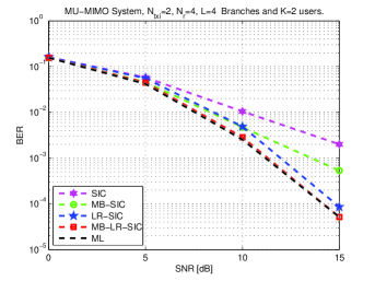
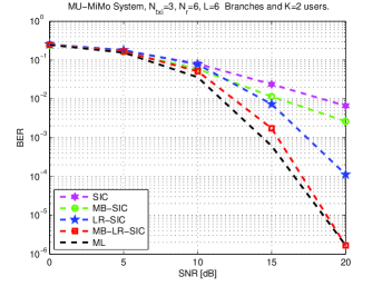
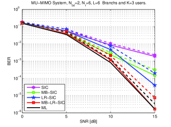
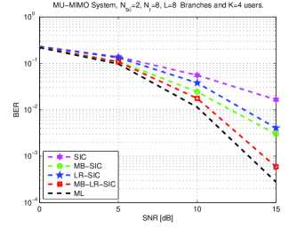
The simulation curves correspond to an average of 3,000 simulation runs, with 500 symbols transmitted per run. In Fig. 4 and Fig. 5, we consider scenario 1, compare the performance of the proposed MB-LR-SIC detector with that of existing detectors where SIC, MB-SIC and LR-SIC all use MMSE linear receive filters, QPSK and 16-QAM modulation, column-norm-based ordering and employ perfectly known channel state information. Note that the performance of the MB-LR-SIC is very close that of the optimum ML detector, even when the modulation order and the number of antennas per user grow, see Figure. 5. In the next experiment, scenario 1 and channel estimation for the different detectors is considered, 550 symbols are transmitted, where 50 symbols are used for training. In Fig. 6 it is shown that the performance of MB-LR-SIC with channel estimation (dotted lines) is still close to the ML detector performance with channel estimation. The curves in Fig. 7 illustrate the behavior of the system performance for the more realistic channel scenario with and dB. The components of correlation matrices and are of the form:
| (23) |
where is the number of antennas and is the correlation index of neighboring antennas ( for the transmit antennas and for the receive antennas). Note that represents an uncorrelated scenario and implies a fully correlated scenario. The curves in Fig. 7 display a loss of performance in all detectors due to the propagation effects. However, the proposed MB-LR-SIC algorithm for these realistic conditions outperforms the other considered techniques and is close to the ML detector.
V Conclusions
This paper introduced a new detection technique for multiuser MIMO systems. The proposed MB-LR-SIC detector employs an LR transformation technique and generates multiple ordering patterns and estimates of symbol vectors, each of these ordering patterns uses SIC detection in the LR domain. This makes possible to generate a set of candidate solutions of the transmitted vector with high reliability. Finally the best candidate is selected using the ML criterion. The MB-LR-SIC detector, besides being conceptually simple, has been shown through simulations that in a realistic scenario and without perfect knowledge of the channel state information (using channel estimation) the performance approaches the optimal ML detector with much lower computational complexity. Due to the higher detection diversity and low computational complexity, compared with the optimal detector, the MB-LR-SIC structure is presented as a viable detection alternative for future MIMO communications systems.
References
- [1] C. J. Foschini and M. J. Gans, “On limits of wireless communications in a fading enviroment when using multiple antennas,” Wireless Pers. Commun., vol. 6, pp. 311 – 335, 1998.
- [2] H. Yao and G. Womell, “Lattice-Reduction-Aided Detectors for MIMO Communication Systems,” in IEEE Global Telecommunications Conference, Taipei, Taiwan, 2002, pp. 575 – 579.
- [3] B. M. Hochwald and S. ten Brink, “Achieving near-capacity on a multiple-antenna channel,” IEEE Transactions on Communications, vol. 51, no. 3, pp. 389 – 399, Mar 2003.
- [4] D. Wiibben, R. Bohnke, V. Kühn, and K.-D. Kammeyer, “Near-maximum-likelihood detection of MIMO systems using MMSE-based lattice-reduction,” in IEEE International Conference on Communications, Taipei, Taiwan, 2004, pp. 798 – 802.
- [5] M. Taherzadeh, A. Mobasher, and A. K. Khandani, “LLL Reduction Achieves the Receiver Diversity in MIMO Decoding,” IEEE Transactions on Information Theory, vol. 53, no. 12, pp. 4801 – 4805, 2007.
- [6] R.C de Lamare, “Adaptive and Iterative Multi-Branch MMSE Decision Feedback Detection Algorithms for Multi-Antenna Systems,” IEEE Transactions on Wireless Communications, vol. 12, no. 10, pp. 5294 – 5308, 2013.
- [7] Y. H. Gan, C. Ling, and W. H. Mow, “Complex Lattice Reduction Algorithm for Low-Complexity Full-Diversity MIMO Detection,” IEEE Transactions on Signal Processing, vol. 57, no. 7, pp. 2701 – 2710, July 2009.
- [8] G.D. Golden, C.J. Foschini, R.A. Valenzuela, and P.W. Wolniansky, “Detection algorithm and initial laboratory results using V-BLAST space-time communication architecture,” Electronics Letters, vol. 35, no. 1, pp. 14 – 16, January 1999.
- [9] K. Lee, J. Chun, and L. Hanzo, “Optimal Lattice-Reduction Aided Successive Interference Cancellation for MIMO Systems,” IEEE Transactions on Signal Processing, vol. 6, no. 7, pp. 2438 – 2443, 2007.
- [10] R.C. de Lamare and R. Sampaio-Neto, “Adaptive reduced-rank equalization algorithms based on alternating optimization design techniques for mimo systems,” Vehicular Technology, IEEE Transactions on, vol. 60, no. 6, pp. 2482–2494, July 2011.
- [11] Peng Li, R.C. de Lamare, and Rui Fa, “Multiple feedback successive interference cancellation detection for multiuser mimo systems,” IEEE Transactions on Wireless Communications, vol. 10, no. 8, pp. 2434–2439, August 2011.
- [12] Peng Li and R.C. de Lamare, “Adaptive decision-feedback detection with constellation constraints for mimo systems,” Vehicular Technology, IEEE Transactions on, vol. 61, no. 2, pp. 853–859, Feb 2012.
- [13] Peng Li and R.C. de Lamare, “Distributed iterative detection with reduced message passing for networked mimo cellular systems,” IEEE Transactions on Vehicular Technology, vol. 63, no. 6, pp. 2947–2954, July 2014.
- [14] R.C. de Lamare and R. Sampaio-Neto, “Minimum Mean-Squared Error Iterative Successive Parallel Arbitrated Decision Feedback Detectors for DS-CDMA Systems,” IEEE Transactions on Communications, vol. 56, no. 5, pp. 778 – 789, May 2008.
- [15] R. Fa and R. C. de Lamare, “Design of Adaptive Multi-Branch SIC Receivers for MIMO Spatial Multiplexing Systems,” in International Symposium on Wireless Communication Systems (ISWCS), Siena-Tuscany, Italy, 2009, pp. 575 – 579.
- [16] E. Karami, “Tracking Performance of Least Squares MIMO Channel Estimation Algorithm,” IEEE Trans. Commun., vol. 55, no. 11, pp. 2201 – 2209, Nov. 2007.
- [17] R.C. de Lamare and R. Sampaio-Neto, “Reduced-rank adaptive filtering based on joint iterative optimization of adaptive filters,” IEEE Signal Processing Letters, vol. 14, no. 12, pp. 980–983, Dec 2007.
- [18] R.C. de Lamare and R. Sampaio-Neto, “Adaptive reduced-rank processing based on joint and iterative interpolation, decimation, and filtering,” IEEE Transactions on Signal Processing, vol. 57, no. 7, pp. 2503–2514, July 2009.
- [19] Zhaocheng Yang, R.C. de Lamare, and Xiang Li, “L1-regularized stap algorithms with a generalized sidelobe canceler architecture for airborne radar,” IEEE Transactions on Signal Processing, vol. 60, no. 2, pp. 674–686, Feb 2012.
- [20] Keke Zu and R.C. de Lamare, “Low-complexity lattice reduction-aided regularized block diagonalization for mu-mimo systems,” IEEE Communications Letters, vol. 16, no. 6, pp. 925–928, June 2012.
- [21] Keke Zu, R.C. de Lamare, and M. Haardt, “Generalized design of low-complexity block diagonalization type precoding algorithms for multiuser mimo systems,” IEEE Transactions on Communications, vol. 61, no. 10, pp. 4232–4242, October 2013.
- [22] D. Milford and M. Sandell, “Simplified Quantisation in a Reduced-Lattice MIMO Decoder,” IEEE Communications Letters, vol. 15, no. 7, pp. 725 – 727, July 2011.
- [23] T. Minka, “The upshapeLightspeed upshapeMatlab toolbox, efficient operations for upshapeMatlab programming, version 2.2,” Microsoft Corp, 17 Dec. 2007.
- [24] J.P. Kermoal, L. Schumacher, and K.I. Perdersen et al., “A stochastic MIMO radio channel model with experimental validation,” IEEE J. Sel. Areas Commun., vol. 20, no. 6, pp. 1211 – 1226, Aug. 2002.