A High Efficiency MAC Protocol for WLANs: Providing Fairness in Dense Scenarios
Abstract
Collisions are a main cause of throughput degradation in WLANs. The current contention mechanism used in IEEE 802.11 networks is called Carrier Sense Multiple Access with Collision Avoidance (CSMA/CA). It uses a Binary Exponential Backoff (BEB) technique to randomise each contender attempt of transmitting, effectively reducing the collision probability. Nevertheless, CSMA/CA relies on a random backoff that while effective and fully decentralised, in principle is unable to completely eliminate collisions, therefore degrading the network throughput as more contenders attempt to share the channel.
To overcome these situations, Carrier Sense Multiple Access with Enhanced Collision Avoidance (CSMA/ECA) is able to create a collision-free schedule in a fully decentralised manner using a deterministic backoff after successful transmissions. Hysteresis and Fair Share are two extensions of CSMA/ECA to support a large number of contenders in a collision-free schedule. CSMA/ECA offers better throughput than CSMA/CA and short-term throughput fairness. This work describes CSMA/ECA and its extensions. Additionally, it provides the first evaluation results of CSMA/ECA with non-saturated traffic, channel errors, and its performance when coexisting with CSMA/CA nodes. Furthermore, it describes the effects of imperfect clocks over CSMA/ECA and present a mechanism to leverage the impact of channel errors and the addition/withdrawal of nodes over collision-free schedules. Finally, experimental results on throughput and lost frames from a CSMA/ECA implementation using commercial hardware and open-source firmware are presented.
Index Terms:
CSMA/ECA, WLAN, MAC, Collision-free, Testbed.L. Sanabria-Russo (luis.sanabria@upf.edu) , J. Barcelo (jaume.barcelo@upf.edu) and B. Bellalta (boris.bellalta@upf.edu) are with the Department of Information and Communication Technologies, Universitat Pompeu Fabra, Barcelona, Spain.
F. Gringoli (francesco.gringoli@ing.unibs.it) is with the Dipartamento di Elettronica per l’Automazione, Università degli Studi di Brescia, Brescia, Italy.
I Introduction
Wireless Local Area Networks (WLANs or WiFi networks [1]) are a popular solution for wireless connectivity, whether in public places, work environments or at home. This technology works over an unlicensed spectrum in the Industrial, Scientific and Medical (ISM) radio bands (at around or GHz), offering a good tradeoff between performance and costs, which is a main reason for its popularity.
The Medium Access Control (MAC) scheme used in WLANs is based on Carrier Sense Multiple Access with Collision Avoidance (CSMA/CA) protocol. It has been widely adopted by manufacturers and consumers, making it inexpensive to implement and an ubiquitous technology. Nevertheless, the ever-growing throughput demands from upper layers are faced with a bottleneck at the WLANs’ MAC [2], which by its nature is prone to collisions that degrade the overall performance as more nodes join the network [3].
The research community has pushed forward many alternatives to the current MAC in WLANs [4, 5, 6, 7, 8, 9, 10, 11, 12, 13, 14], but when a proposal deviates too much from CSMA/CA, or some time-critical operations are modified, its hardware implementation as part of WLANs’ MAC often becomes unlikely [15], with the standardisation process taking many years without certainty of approval [2].
A CSMA/CA replacement should be able to provide advantages in terms of throughput, spectrum efficiency and number of supported contenders. All of the aforementioned without sacrificing short-term throughput fairness. Furthermore, WLANs implementing such a replacement must also serve existing users, which means they have to be backwards compatible.
A suitable candidate, and the one to be evaluated in this work, is called Carrier Sense Multiple Access with Enhanced Collision Avoidance (CSMA/ECA) [8]. It is capable of attaining higher throughput than CSMA/CA by making a simple modification to the contention mechanism, thus keeping maintaining compatibility. In CSMA/ECA, nodes use a deterministic backoff after successful transmissions, constructing a collision-free schedule among successful contenders in a fully decentralised way. This backoff mechanism ensures that more channel time is spent on successful transmissions rather than recovering from collisions, thus increasing the throughput of the network. Further enhancements (or extensions), like Hysteresis and Fair Share [16] allow CSMA/ECA to support many more contenders in a collision-free schedule. Moreover, CSMA/ECA and its extensions are designed for allowing nodes to transmit as frequently as possible while keeping an even distribution of the available bandwidth among users.
The 802.11 High Efficiency WLAN (HEW) Task Group (TG) envisions very crowded scenarios as one of the future challenges for WLAN protocols [17, 18], specifically those usually encountered at stadiums or conference rooms. Further, if the need for serving many users is combined with the increased throughput demands from the upper layers, a performance improvement at the MAC becomes paramount. Although many studies have been made analysing the performance of CSMA/ECA [8, 16, 9, 19], there are still several open aspects that require further attention and additional insight to consider CSMA/ECA as a potential CSMA/CA replacement. Namely, neither assesses the protocol’s backwards compatibility property or its behavior under non-saturated traffic conditions while serving many users. Furthermore, the impact of channel errors, node addition/withdrawal, and imperfect clocks over the deterministic backoff mechanism is also lacking.
This paper fills those gaps by extending [16], and consolidates the push for CSMA/ECA as a potential replacement of CSMA/CA for next generation WLANs. In detail, this paper provides the following contributions:
-
•
First results on the achievable throughput and delay of CSMA/ECA with Hysteresis and Fair Share under non-saturated traffic conditions for very large number of nodes.
-
•
The impact of imperfect clocks and channel errors on CSMA/ECA with Hysteresis and Fair Share’s deterministic backoff and its consequences on the achieved performance.
-
•
Formulation of the throughput bounds for CSMA/ECA with Hysteresis and Fair Share.
-
•
Introduce the Schedule Reset mechanism for reducing the schedule length in case of users withdrawing from the contention (non-saturated traffic), or when its length is increased due to channel errors.
-
•
Coexistence and backwards compatibility with CSMA/CA nodes under different traffic conditions.
-
•
First implementation of CSMA/ECA with Hysteresis in real hardware and the experimental results in a crowded WLAN testbed.
Results, derived from a modified version of the COST [20] simulator show that CSMA/ECA with Hysteresis and Fair Share is capable of accommodating many users in collision-free schedules. As tests in a mixed network with different proportions of CSMA/CA and CSMA/ECA nodes show, the aggregated throughput is higher than the observed in CSMA/CA-only networks. Furthermore, at low number of total contenders CSMA/CA’s throughput is actually improved, while it is degraded in crowded scenarios. This constitutes a motivation for a change towards CSMA/ECA.
Beyond simulations results, the implementation of CSMA/ECA prototypes[21, 22, 23, 24] show that the construction of collision-free schedules using a deterministic backoff after successful transmissions is possible and results in a throughput increase by reducing the number of corrupted frames. We then present the first real hardware implementation of CSMA/ECA with Hysteresis using the open firmware OpenFWWF [25]. Results show that CSMA/ECA is able of providing higher throughput and lower losses than CSMA/CA for the same number of contenders.
An overview of similar decentralised and collision-free MAC protocols for WLANs is provided in Section II. CSMA/ECA, as well as its extensions for allocating many contenders in a collision-free schedule are explained in Section III. Section IV details the simulation environment for testing CSMA/ECA, while Section V explains the results. An overview of CSMA/ECA real-hardware implementation and testbed description is compiled in Section VI, followed by a summary of the still missing CSMA/ECA features needed to become the next CSMA/CA replacement in Section VII. Conclusions are drawn in Section VIII.
II Related Work
Time in WLANs is divided into tiny empty slots of fixed length , collisions, and successful slots of length and , respectively. Collision and successful slots contain collisions or successful transmissions, making them several orders of magnitude larger than empty slots (. One of the effects of collisions is the degradation of the network performance by wasting channel time on collisions slots.
Recent advances in the WLANs PHY [2, 26] push the research community towards the development of MAC protocols able to take advantage of a much faster PHY. By reducing the time spent in collisions nodes are able to transmit more often, which in turn translates to an increase in the network throughput. Further, the upcoming MAC protocols for WLANs should work without message exchange between contenders, that is, work in a fully decentralised fashion in order to avoid injecting extra control traffic that may reduce the data throughput.
Performing time slot reservation for each transmission is a well known technique for increasing the throughput and mantanining Quality of Service (QoS) in TDMA schemes, like LTE [27]. Applying the same concept to CSMA networks by modifying DCF’s random backoff proceedure provides similar benefits [10]. The following are MAC protocols for WLANs, decentralised and capable of attaining greater throughput than CSMA/CA by constructing collision-free schedules using reservation techniques. A survey of collision-free MAC protocols for WLANs is presented in [28]. In this paper we only overview those that are similar to CSMA/ECA.
II-A Zero Collision MAC
Zero Collision MAC (ZC-MAC) [29] achieves a zero collision schedule for WLANs in a fully decentralised way. It does so by allowing contenders to reserve one empty slot from a predefined virtual schedule of -slots in length. Backlogged stations pick a slot in the virtual cycle to attempt transmission. If two or more stations picked the same slot in the cycle, their transmissions will eventually collide. This forces the involved contenders to randomly and uniformly select other empty slot from those detected empty in the previous cycle plus the slot where they collided. When all stations reserve a different slot, a collision-free schedule is achieved.
ZC-MAC is able to outperform CSMA/CA under different scenarios. Nevertheless, given that the length of ZC MAC’s virtual cycle has to be predefined without actual knowledge of the real number of contenders in the deployment, the protocol is unable to provide a collision-free schedule when . Furthermore, if is overestimated (), the fixed-width empty slots between each contender’s successful transmission are no longer negligible and contribute to the degradation of the network performance. Additionally, ZC-MAC nodes require common knowledge of where the virtual schedule starts/ends. This is not considered in CSMA/CA and constitutes an obstacle towards standardisation.
II-B Learning-MAC
Learning-MAC [28] is another MAC protocol able to build a collision-free schedule for many contenders. It does so defining a learning strength parameter, . Each contender starts by picking a slot for transmission of the schedule of length at random with uniform probability. After a contender picks slot , its selection in the next schedule, , will be conditioned by the result of the current attempt. (1) and (2) extracted from [28] show the probability of selecting the same slot in cycle .
| (1) |
| (2) |
for all . That is, if a station successfully transmitted in , it will pick the same slot on the next schedule with probability one. Otherwise, it follows (2).
The selection of implies a compromise between fairness and convergence speed, which the authors determined to provide satisfactory results.
L-MAC is able to achieve higher throughput than CSMA/CA with a very fast convergence speed. Nevertheless, the choice of suppose a previous knowledge of the number of empty slots (, where is the number of contenders), which is not easily available to CSMA/CA or may require a centralised entity [14].
Further extensions to L-MAC introduced an Adaptative schedule length in order to increase the number of supported contenders in a collision-free schedule. This adaptive schedule length is doubled or halved depending on the presence of collisions or many empty slots per schedule, respectively. The effects of reducing the schedule length may provoke a re-convergence phase which can result in short-term fairness issues. Moreover, L-MAC nodes also require common knowledge of the start/end of the schedule.
III Carrier Sense Multiple Access with Enhanced Collision Avoidance (CSMA/ECA)
CSMA/ECA [8] is a fully decentralised and collision-free MAC for WLANs. It differs from CSMA/CA in that it uses a deterministic backoff, after successful transmissions, where is the minimum contention window of typical value . By doing so, contenders that successfully transmitted on schedule , will transmit without colliding with other successful nodes in future cycles [10].
Collisions are handled as in CSMA/CA, which is described in Algorithm 1. In Algorithm 1, the node starts by setting the retransmissions counter and backoff stage to zero ( and respectively, with the maximum backoff stage, and the retransmissions limit. The typical value for is ), then generates a random backoff, . When the Acknowledgement (ack) for a sent packet is not received by the sender a collision is assumed. Upon collision, the involved nodes will double their contention window by incrementing their backoff stage in one and use a random backoff, . This procedure is described between Line 1 and 1 of Algorithm 1.
Algorithm 2 provides an explanation of CSMA/ECA’s deterministic backoff mechanism, which main difference with CSMA/CA (and therefore with Algorithm 1) relies on the selection of a deterministic backoff after a successful transmission (compare Line 1 in Algorithm 1 with Line 2 in Algorithm 2). Figure 1 shows an example of CSMA/ECA dynamics with four contenders.
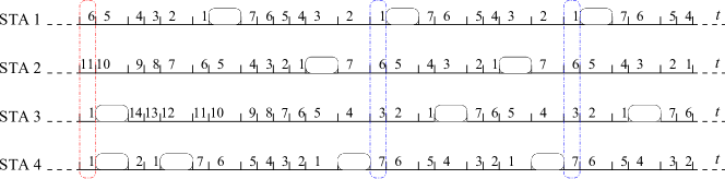
In Figure 1, the STA-# labels represent stations willing to transmit. The horizontal lines represent a time axis with each number indicating the amount of empty slots left for the backoff to expire. Stations willing to transmit begin the contention for the channel by waiting a random backoff, . The first outline highlights the fact that stations STA-3 and STA-4 will eventually collide because they have selected the same . After recomputing the random backoff, STA-4’s attempt results in a successful transmission, which instructs the node to use a deterministic backoff, in this case. By doing so, all successful STAs will not collide among each other in future cycles.
Collision slots being orders of magnitude larger than empty slots degrade the network performance. When CSMA/ECA builds the collision-free schedule all contenders are able to successfully transmit more often, increasing the aggregated throughput beyond CSMA/CA’s. Figure 2, shows the average aggregated throughput of CSMA/ECA, CSMA/CA and collision-free protocolos presented in Section II, namely ZC-MAC and L-MAC [28].
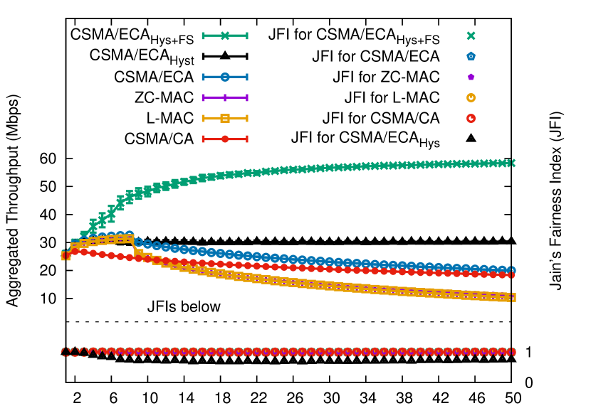
Referring to Figure 2, CSMA/ECA is able to achieve an aggregated throughput that goes beyond CSMA/CA up until the number of contenders is greater than ( in the case of the figure). Beyond this point, the network will have a mixed behaviour relating to backoff mechanisms: some nodes will successfully transmit and use a deterministic backoff while others will collide due to the lack of empty slots and return to a random backoff. As more contenders join the network, CSMA/ECA performance will approximate to CSMA/CA’s. This effect is also observed in ZC-MAC and L-MAC. It happens becasue the virtual cicle used by these protocolos ( for ZC-MAC and for L-MAC in Section II) in lower than the number of contenders, 111L-MAC and ZC-MAC curves in Figure 2 appear to yield the same aggregated throughput. This is because these protocols do not consider an increase in the backoff stage after a failed transmission, augmenting the collision probability beyond CSMA/CA’s. An adaptation of the schedule length leverages this issue, which is preseted in [28] as Adaptive L-MAC and L-ZC..
The JFI curves in Figure 2 show the Jain’s Fairness index for all tested protocols. Showing a JFI equal to one suggests that the available throughput is shared evenly among all stations.
III-A Supporting many more contenders
As was mentioned before, CSMA/ECA is only able to build a collision-free schedule if the number of contenders , is less or equal than . When , collisions reappear.
To be able to attain a collision-free schedule even when the number of contenders exceeds , we introduce Hysteresis. Hysteresis is a property of the protocol that instructs nodes not to reset their backoff stage () after successful transmissions, but to use a deterministic backoff , where . This measure allows the adaptation of the schedule length, admitting many more contenders in a collision-free schedule. This idea of a schedule is significantly different from the virtual schedule required by the protocols described in Section II, that is, CSMA/ECA with Hysteresis does not require a previous knowledge of the number of contenders, the result of previous transmissions or the start/end of the schedule, easing its implementation in real hardware.
Hysteresis enables CSMA/ECA nodes to have different schedules (), carrying the undesired effect of unevenly dividing the channel time among contenders (i.e., some nodes will have to wait more in order to attempt transmissions).
This unfairness issue is solved by instructing nodes at backoff stage to transmit packets on each attempt, thus proportionally compensating those nodes at higher backoff stages. This additional extension to CSMA/ECA is called Fair Share. CSMA/ECA with Hysteresis and Fair Share will be referred to as CSMA/ECA in order to distinguish it from what was described until this point.
The idea of allowing the transmission of more packets to stations that transmit less often was initially proposed by Fang et al. in [28]. It was later adapted to CSMA/ECA and named Fair Share in [16]. Figure 2 shows the JFI for CSMA/CA as well as for CSMA/ECA.
In Figure 2, the only curve deviating from JFI = 1 is CSMA/ECA with Hysteresis (CSMA/ECA), suggesting an uneven partition of the channel access time among contenders (which is fixed with Fair Share).
| Notation | Description |
|---|---|
| Backoff stage | |
| Maximum backoff stage | |
| Random backoff | |
| Deterministic backoff | |
| Minimum Contention Window | |
| CSMA/ECA | CSMA/ECA with Hysteresis |
| CSMA/ECA | CSMA/ECA with Hysteresis and Fair Share |
| CSMA/ECA | CSMA/ECA with Hysteresis and Maximum Aggregation |
| CSMA/CA | CSMA/CA with Fair Share |
| CSMA/ECA | CSMA/CA with Maximum Aggregation |
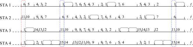
Algorithm 3 describes CSMA/ECA, Table I provides a short list of notations used throughout the text, while an example of CSMA/ECA with four contenders is shown in Figure 3. In the figure the first outline indicates a collision between STA-3 and STA-4, which will provoke an increment on both stations’ backoff stage (). Once STA-4’s random backoff expires, CSMA/ECA instructs the station to transmit packets, and then use a deterministic backoff, . The same procedure is followed by STA 3.
With Hysteresis and Fair Share, CSMA/ECA is able to achieve greater throughput than CSMA/CA and for many more contenders, as shown also in Figure 2. In the figure, the CSMA/ECA curve shows a greater throughput because collisions are eliminated and Fair Share allows nodes to send packets upon each transmission. This throughput increase is the result of aggregation via Fair Share. It carries the negative effect of raising the average time between successful transmissions (see Section V-A3), which may affect delay-sensitive traffic, like gaming or live video/voice/tv streaming.
Channel errors, hidden-nodes, or unsaturated traffic conditions will disrupt any collision-free schedule, generate collisions and push all stations’ backoff stages to the maximum value very quickly (contributing to the delay increase). This issue is leveraged with the Schedule Reset mechanim, introduced in Section III-G.
III-B The effects of Aggregation
Fair Share is an A-MPDU aggregation mechanism [30] that coupled with the collision-free schedule built by CSMA/ECA is able to provide short-term fairness. However, it also improves the throughput since the aggregation process makes the packet transmission more efficient by reducing overheads. Furthermore, the level of aggregation provided by Fair Share depends only on the buffer occupancy and the current backoff stage.
The downside of Fair Share is that it may increase the time between two consecutive transmissions from the same node, which may affect negatively delay-sensitive applications such as gaming or high definition real-time video. An example of the duration of a transmission, , is provided by (5) in the following Section III-C.
In scenarios where short-term fairness and the time between consecutive transmissions are not relevant, Fair Share can be replaced by Maximum Aggregation (MaxAg), which will significantly improve the system throughput. In Maximum Aggregation all nodes aggregate as many packets as possible at every transmission, i.e., they send packets in each attempt.
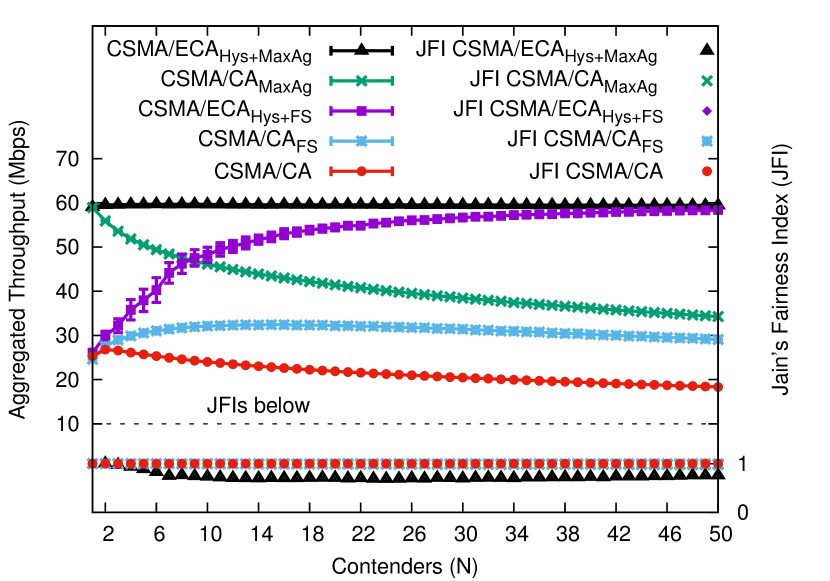
Figure 4 shows the aggregated throughput for CSMA/ECA, CSMA/ECA, CSMA/CA using the Fair Share mechanism (CSMA/CA), and CSMA/CA. JFIs are shown below. Although CSMA/CA and CSMA/CA perform aggregation, collisions degrade the aggregated throughput as more contenders attempt transmission. On the other hand, CSMA/ECA is able to build a collision-free schedule and takes advantage of the aggregation provided by Fair Share, which opposed to just using CSMA/ECA, it is fair.
To summarise the effects of using aggregation:
-
•
It increases the aggregated throughput: because nodes are able to send multiple packet in each attempt, the system throughput is increased. Moreover, Fair Share compensates those nodes at higher backoff stages to ensure throughput fairness.
-
•
Maximum aggregation supposes the deactivation of the Fair Share mechanism: performing maximum aggregation upon each transmission attempt is equivalent to having different schedule lengths and not compensating nodes at higher backoff stages. Although the aggregated throughput increases, this results in an uneven distribution of the channel time among contenders, which renders it unfair.
-
•
Longer periods between transmission attempts: given that each transmission takes longer, the time between transmission attempts also increases. This may specially affect delay-sensitive applications.
Since we consider that fairness and a short inter-transmission time are even more important than raw throughput for the next generation of WLANs, we keep CSMA/ECA as the reference protocol.
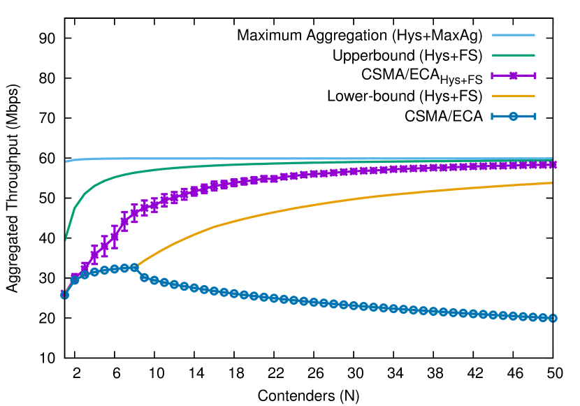
III-C Throughput bounds of CSMA/ECA
They correspond to the maximum and minimum achievable throughput without the possibility of collisions using Hysteresis and Fair Share. The ideal CSMA/ECA network uses the minimum schedule length that guarantees a collision-free operation. That is, with a schedule length of , where . Using this minimum schedule length, nodes will be at the same backoff stage if . Otherwise, nodes would occupy the -th backoff stage and the other nodes the -th one. The system throughput is computed as follows:
| (3) |
where and are the throughput achieved by the nodes at the -th and -th backoff stages sending and packets respectively. These are given by:
| (4a) | |||
| (4b) | |||
where is the data payload, and are the duration of the transmission of and packets, respectively; is the duration of an empty slot. Additionally, derives from (5):
| (5) |
where s is the duration of the PHY-layer preamble and headers, s is the duration of an OFDM (Orthogonal Frequency Division Multiplexing) symbol. SF is the Service Field ( bits), MD is the MPDU Delimiter ( bits), MH is the MAC header ( bits), TB is the number of Tail Bits ( bits), is the Block-ACK length ( bits) and is the number of bits in each OFDM symbol. SIFS, DIFS and values can be found in Table II.
The Lower-bound is derived from considering the operation of an ideal CSMA/ECA network. Nodes use the minimum backoff stage possible and aggregate proportionally, thus yielding the minimum throughput achievable by a CSMA/ECA network. It is computed following (3) with and .
The Upper-bound is obtained from considering the operation of a network using CSMA/ECA, but forcing nodes to use the maximum backoff stage for determining the cycle length and the level of aggregation. It is also computed using (3) but considering that all nodes are in the maximum backoff stage () and therefore .
The maximum throughput achievable is the result of deactivating the Fair Share rules by forcing nodes to use maximum aggregation regardless of their backoff stage. This is called Maximum Aggregation (Hys+MaxAg) in Figure 5. It can be derived from (3) considering and .
It is interesting to see in Figure 5 how collisions force colliding CSMA/ECA contenders to increase their backoff stage and aggregate more with Fair Share. This explains why the CSMA/ECA curve separates itself from the Lower-bound at a very low number of contenders.
Although using maximum aggregation (see Maximum Aggregation (Hys+MaxAg) curve in Figure 5) increases the throughput it carries the effect of unevenly distributing the available bandwidth among contenders, as mentioned in Section III-B.
The tools for deriving these two curves are available as MATLAB functions in [31].
III-D Clock drift issue in descentralized collision-free MAC protocols
CSMA/ECA relies on stations being able to correctly count empty slots and consequently attempt transmissions in the appropriate slot according to the backoff timer. Failure to do so may be caused by clock imperfections inside the Wireless Network Interface Cards (WNIC), which is commonly referred to as clock drift. As pointed out in [32], clock drift is a common issue that degrades the throughput in distributed collision-free MAC protocols like the ones reviewed in Section II.
While miscounting empty slots have no significant effect on CSMA/CA’s throughput [32], it has a direct impact on CSMA/ECA. In a collision-free schedule with saturated CSMA/ECA contenders, a station miscounting empty slots will drift to a possibly busy slot, collide and force a re-convergence (if possible) to a collision-free schedule (see Section V-A2).
III-E Channel errors
Failed transmissions due to channel errors are handled as collisions by CSMA/ECA. Therefore, collision-free periods under this type of channel model are frequently interrupted. In order to accelerate the convergence to collision-free schedules in presence of channel errors CSMA/ECA instruct nodes to stick to the current deterministic backoff even after stickiness number of consecutive failed transmissions. Stickiness has been introduced to CSMA/ECA in [14], where it is described and evaluated. Stickiness allows for a faster convergence towards a collision-free schedule, especially when performing under heavy channel errors.
Failed transmissions due to channel errors also means that a few moments of operation under a noisy channel can increase the contenders’s deterministic backoff to its maximum value. Such event carries the undesired effects of increasing the time between successful transmissions and reducing the overall system throughput due to fewer collision-free periods of operation.
III-F Hidden terminals
One key characteristic of IEEE 802.11 devices is that their carrier sense range is at least two times greater than their data range [33]. In this situation, the impact of hidden nodes can be considered to be low. This is because a given transmission could only be interfered by other transmissions from very distant nodes with energy levels not higher than the noise floor, which using modern radios can be easily solved by the capture effect. However, in specific deployments, where obstacles play also an important role on the propagation effects, hidden nodes may appear, causing asynchronous packet collisions [34].
In the case of CSMA/ECA WLANs, the same negative effects as in IEEE 802.11 WLANs are expected. In addition, collisions with hidden terminals will cause nodes to leave any collision-free schedule, as channel errors do, thus continuously disrupting any attempt of collision-free operation.
III-G Schedule Reset Mechanism
CSMA/ECA instructs nodes to keep their current backoff stage after a successful transmission (resetting it to zero only if the node empties its MAC queue, see line 3 in Algorithm 3). This is done in order to increase the cycle length and provide a collision-free schedule for many contenders, which is desirable in dense scenarios.
Nevertheless, having a big deterministic backoff increases the time between successful transmissions. If not operating in a scenario with many nodes, the empty slots between transmissions are not longer negligible and degrade the overall throughput of the system. For instance, if nodes withdraw from the contention (i.e.: empty their MAC queue, or move to other network) their previously used slots will now be empty. On the other hand, in scenarios with channel errors contenders rapidly end up with the largest deterministic backoff, remaining there until the MAC queue empties. Nodes should be aware of this issue and pursue opportunities to reduce their deterministic backoff, without sacrificing too much in collisions.
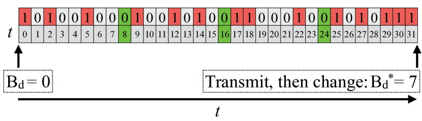
The Schedule Reset mechanism for CSMA/ECA consists on finding the smallest collision-free schedule (if any) between a contender’s transmissions and then change the node’s deterministic backoff to fit in that schedule. Take a contender with as an example. By listening to the slots between its transmissions, it is possible to determine the availability of smaller (and possibly) collision-free schedules.
Figure 6 shows the slots between the transmissions of a contender with . Starting from the left, the current means that the first slot will be filled with the contender’s own transmission. Each following slot containing either a transmission or a collision is identified with the number one, while empty slots are marked with a zero. Notice that the highlighted empty slots appear every eight slots, suggesting that a schedule reduction from to is possible; where is the new deterministic backoff assigned by Schedule Reset222 (see Table II). So the change is made to the backoff stage, . In this case from , to . This means that any new schedule must also be a power of two.. The schedule change is performed after the contender’s next successful transmission.
III-G1 A conservative schedule reduction
Schedule Reset is described in Algorithm 4. Each contender starts filling a bitmap of size with the information observed in each passing slot during consecutive successful transmissions (sxTx in Algorithm 4); where is the biggest deterministic backoff, and is referred to as the Schedule Reset threshold from this point forward.
Each bit in the bitmap is the result of a bitwise OR operation between its current value and the state of the corresponding slot. This is shown in Line 4 in Algorithm 4, where is a function that evaluates to if the slot corresponding to is empty in iteration , ; or otherwise. After iterations, the bitmap is evaluated (line 4 in Algorithm 4).
Schedule Reset tests all possible deterministic backoffs that are smaller than the current (lines 4-4 in Algorithm 4), starting with the smallest one. If the corresponding bits in the bitmap are registered as empty, the process is stopped and the change to the new deterministic backoff is made (lines 4-4 in Algorithm 4). Otherwise, the process is restarted after the next successful transmission.
Using Figure 6 as an example, we can see that , for . This means that the transmission slots corresponding to a deterministic backoff, are free, therefore a change of schedule is possible. In case of suffering a collision immediately after applying the schedule reduction, the node reverses the changes made by Schedule Reset before handling the collision.
III-G2 Aggressive approach to face channel errors
the default ensures that the bitmap registers all the transmission slots in the network (assuming saturated traffic and a perfect channel), providing enough information for performing the schedule reduction without disrupting collision-free schedules.
Nevertheless, this can be rendered too conservative and unnecessary because nodes randomly leave the collision-free schedule due to errors. This condition produces Schedule Reset bitmaps that do not contain enough information for successfully avoiding collisions after the schedule reduction. This is also true for any .
This effect is leveraged by setting , meaning that the bitmap is filled with the information of slots between only two consecutive transmissions. This measure increases the frequency of schedule reset attempts. Furthermore, incrementing the node’s stickiness after a successful reduction of the schedule allows for a faster convergence towards a collision-free schedule, especially when performing under heavy channel errors.
III-H Backwards compatibilty and coexistence
CSMA/ECA springs from a modification to CSMA/CA’s backoff mechanism. It keeps the range of values CSMA/CA nodes use to draw a random backoff (i.e., use the same and ), allowing CSMA/ECA contenders to coexist with CSMA/CA nodes in the same network. Further, the selection of CSMA/ECA’s deterministic backoff, , is the expected value for the current backoff stage () [16], which ensures fairness among contenders. An overview of the attained throughput for different proportions of CSMA/ECA and CSMA/CA nodes is presented in Section V-C.
IV Simulation Scenario
This section provides the simulation parameters for testing CSMA/ECA under two different traffic conditions, namely saturated and non-saturated. We also provide details on how channel errors are modelled and what are its effects over the transmissions. Further, the simulation of the clock drift effect, Schedule Reset parameters, and the coexistence with CSMA/CA are also subjects to be addressed in this section.
IV-A Scenario details
Results are obtained by running multiple simulations over a modified version of the COST simulator [20], available at [35]. PHY and MAC parameters are detailed in Table II. Some assumptions were made in order to test the performance at the MAC layer:
-
•
Unspecified parameters follow the IEEE 802.11n ( GHz) amendment.
-
•
All nodes are in communication range.
-
•
No Request-to-Send (RTS) or Clear-to-Send (CTS) messages are used.
-
•
Collisions take as much channel time as successful transmissions.
The aforementioned assumptions ensure that the simulation results are just effects of the MAC behaviour. If not mentioned otherwise, results are derived from 20 simulations of 100 seconds in length, each one with a different seed. Figures also show the standard deviation.
| PHY | |
|---|---|
| Parameter | Value |
| PHY rate | 65 Mbps |
| Empty slot | |
| DIFS | |
| SIFS | |
| MAC | |
| Parameter | Value |
| Maximum backoff stage () | 5 |
| Minium Contention Window () | 16 |
| Maximum retransmission attempts | 6 |
| Data payload (Bytes) | 1024 |
| MAC queue size (Packets) | 1000 |
IV-B Saturated and Non-saturated stations
A saturated station always has packets in its MAC queue. This is modelled by setting the packet arrival rate to the MAC queue () to a value greater than the achievable throughput. To ensure saturation, stations are set to fill their MAC queue at Mbps, which is purposefully greater than the effective capacity of the channel.
To evaluate the performance under non-saturated conditions, stations need to be able to empty their MAC queues. To do so, the packet arrival rate to the MAC queue is set to Mbps. These values of have proven to produce the desired effects.
IV-C Performance under clock drift
Clock drift is simulated by setting a drift probability, . Each station has a probability of of miscounting one slot more, and of miscounting one slot less. This approach follows the one proposed by Gong et. al in [32].
IV-D Channel errors
Channel errors are modeled by assigning a probability of a packet being corrupted by the channel, . That is, in a single packet transmission there is probability that the transmission will not be acknowledged. If the transmission is an A-MPDU (like in the case of CSMA/ECA), will affect each MPDU individually and independently. Therefore, an A-MPDU transmission will be considered a complete failure only if all frames in the aggregation are affected by the channel error probability.
All results are shown with stickiness equal to one (see Section III-E). That is, after a colision, CSMA/ECA nodes will use a random backofff. Nevertheless, in Section V-D curves described as dynStick temporarily increase the node’s stickiness to two after a successful reduction of the schedule (using a random backoff after two consecutive collisions). This increase is done in order to converge faster to collision-free schedules when operating with channel errors.
IV-E Coexistance with CSMA/CA
To test the performance of CSMA/CA and CSMA/ECA stations in the same network, simulations are set with a CSMA/CA node density of 1/4, 1/2 and 3/4 of the total.
IV-F Applying Schedule Reset
A set of results under saturated conditions and channel errors applying Schedule Reset (see Section III-G) are provided. Some of the results are generated with a , or aggressive Schedule Reset (indicated as aggr. in the figures). These settings provide the highest throughput under the tested conditions, and also in the real hardware implementations such as the one shown in Section VI.
V Results
V-A Saturated nodes
In CSMA/CA, a large number of saturated nodes will normally be related to a high collision probability. This effect is in part the result of resetting the backoff stage after a successful transmission and the generation of a new random backoff. However, this scenario provides an advantageous condition to CSMA/ECA nodes. In saturation, CSMA/ECA nodes build a collision-free schedule and stick to their deterministic backoff as long as they transmit successfully, effectively eliminating collisions.
This section aims at overviewing the throughput of CSMA/CA and CSMA/ECA in saturation, as well as the collision probability, the average time between successful transmissions and the effect of clock drift over the throughput.
V-A1 Throughput
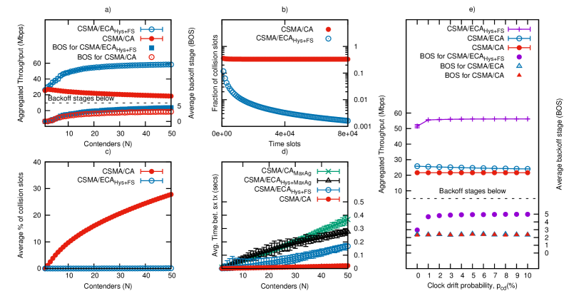
CSMA/ECA nodes are able to build a collision-free schedule, use the channel more efficiently, and experience a throughput increase as seen in Figure 7a. Hysteresis allows the allocation of more contenders by increasing the length of the collision-free schedule, while Fair Share ensures an even distribution of the available throughput. This is reflected by the average backoff stage, which value increases with the number of contenders. In contrast, CSMA/CA throughput keeps decreasing due to an augmented number of collisions as the number of nodes increases (see Figure 7c). Further, Figure 7b shows the fraction of collision slots for CSMA/ECA and CSMA/CA as simulation time passes. In the figure, is appreciated how the fraction of collision slots keeps decreasing once CSMA/ECA reaches collision-free operation.
V-A2 Effect of clock drift over the achieved throughput in saturation
Figure 7e shows the network aggregated throughput with 16 saturated stations and an increasing clock drift probability.
In Figure 7e, a station has a clock drift probability equal to . Each station has a probability of of miscounting one slot more, and of miscounting one slot less. Because CSMA/CA is based on a random backoff, miscounting slots has no significant effect on the throughput. For the CSMA/ECA curve, it is possible to appreciate a slight decrease of the throughput as increases, caused by collisions due to the drift.
The CSMA/ECA curve in Figure 7e shows instead an increase of the aggregated throughput as grows. Collisions make CSMA/ECA contenders to increment their backoff stage and aggregate packets for transmissions according to Fair Share, effectively increasing the throughput.
As it also can be appreciated in the figure, the average backoff stage for CSMA/ECA contenders increases rapidly to its maximum value (), reducing the effect of clock drift over CSMA/ECA nodes given that their transmissions would now be separated by more slots.
V-A3 Time between successful transmissions
It is related to the elapsed time between the contention for transmission and the reception of an ACK.
In Figure 7d all tests with maximum aggregation, namely CSMA/CA and CSMA/ECA, have an increased average time between successful transmissions. This is due to the multiple packets that are sent in each attempt. CSMA/CA, though, has an increased value due to collisions also taking longer channel time.
Although CSMA/ECA has an increased average time between successful transmissions due to Fair Share, it has a lower metric when compared with the maximum aggregation curves in Figure 7d.
V-B Non-saturated nodes
Emptying the MAC queue in CSMA/ECA means that nodes will reset their backoff stage to zero and use a random backoff when a new packet arrives at the queue, breaking any collision-free operation in CSMA/ECA. The following show the impact over throughput, delay and time between successful transmissions when using CSMA/CA and CSMA/ECA in non-saturated conditions.
V-B1 Throughput
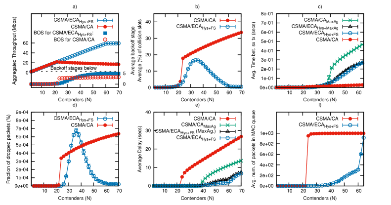
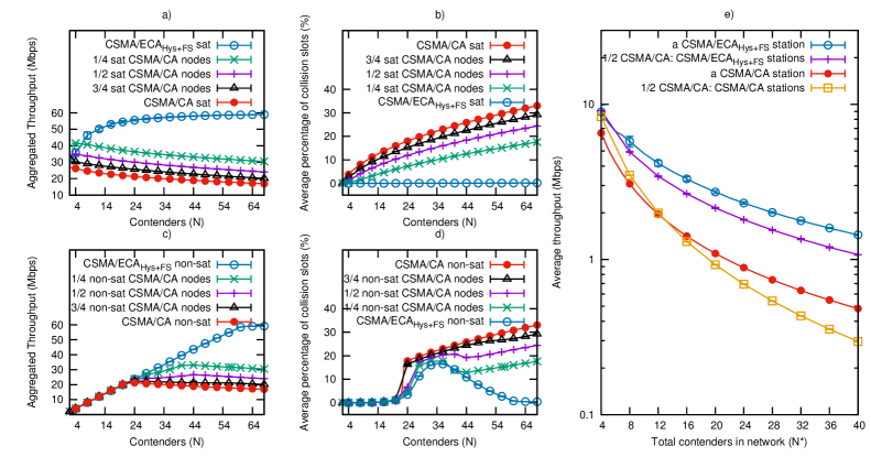
In Figure 8a, the aggregated throughput increases linearly for the CSMA/CA curve until saturation is reached at around 22 nodes, where the throughput begins to degrade. The CSMA/ECA curve has a similar behavior, entering saturation at around 60 nodes. Further, at around 30 nodes we see an increase in the average backoff stage for CSMA/ECA contenders which suggests an increment in collisions. This effect is shown in Figure 8b and Figure 8d, where at around 35 nodes CSMA/ECA contenders start colliding and dropping packets.
As indicated by Figure 8b, when CSMA/ECA nodes suffer from an increasing number of collisions. This is due to nodes emptying their MAC queue quicker due to Fair Share, as shown in Figure 8f and re-entering the contention with a random backoff every time a new packet arrives.
This increase in collisions may also cause the dropping of packets due to reaching the maximum retransmission limit. As CSMA/ECA drops more packets after reaching such limit (see line 3 in Algorithm 3), it shows a higher fraction of dropped packets in Figure 8d.
Beyond 35 contenders, the MAC queue of CSMA/ECA nodes starts to fill up, gradually allowing longer periods of collision-free operation due to CSMA/ECA nodes getting saturated. This allows CSMA/ECA to outperform CSMA/CA.
V-B2 Delay
This metric refers to the elapsed time between the injection of a packet into the station’s MAC queue and the reception of an ACK for such packet.
In Figure 8e, a rapid increase in the delay for CSMA/CA nodes is appreciated at the saturation point (around 20 contenders), whereas CSMA/ECA’s delay is still low.
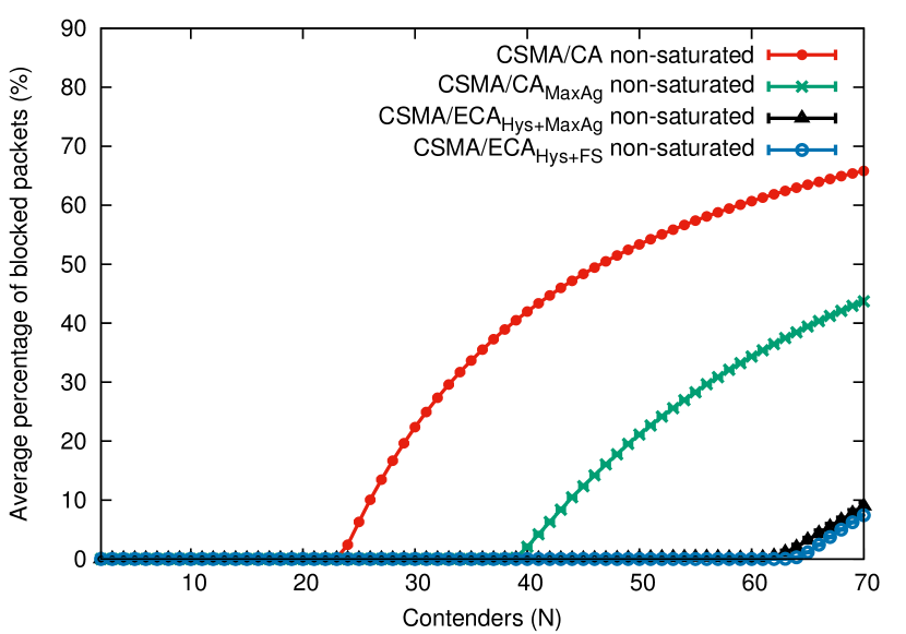
Further, with CSMA/ECA the percentage of blocked packets from the MAC queue is lower than CSMA/CA or CSMA/CA (see Figure 9). This is due to the construction of collision-free schedules which ensure that large A-MPDU transmissions do not suffer from collisions.
As CSMA/ECA nodes get saturated, the delay increases due to longer queueing and contention time (see the number of packets in the MAC queue for CSMA/ECA nodes in Figure 8f and how it is related to the increase in delay shown in Figure 8e).
Figure 8c shows the average time between successful transmissions. It is possible to see from the figure that when CSMA/ECA approaches the saturation point the average time between successful transmissions increases, resembling Figure 7d.
V-C Coexistence with CSMA/CA
CSMA/ECA is thought to be an evolution of CSMA/CA given its similarities and the ability to coexists with the latter. This section provides simulations results for a setup of different proportions of CSMA/CA nodes in a network where there are also CSMA/ECA contenders, that is: 1/4, 1/2 and 3/4 of the total nodes run CSMA/CA, while the rest uses CSMA/ECA. This network configuration will be referred to as mixed network setup from here on.
V-C1 Throughput
Figure 10a shows the network throughput for different proportions of CSMA/CA nodes in a mixed network setup.
In the figure it is appreciated how the mixed network setups curves lay between the CSMA/CA and CSMA/ECA curves. As the proportion of CSMA/CA nodes decreases, the throughput increases as the result of a lower probability of collision, as can be seen in Figure 10b. A similar behaviour is observed when testing the same proportion of nodes under non-saturated conditions. Figure 10c and Figure 10d show the average aggregated throughput and fraction of collisions slots in a non-saturated mixed network setup.
As shown in Figure 10a and Figure 10c, at a lower proportion of CSMA/CA nodes () the average aggregated throughput is the greatest among the tested mixed network setups. This is because collisions trigger Hysteresis and Fair Share in CSMA/ECA nodes, lowering the number of times these nodes enter in a contention and reducing the overall collision probability when compared to an only CSMA/CA network (see Figure 10b, Figure 10d and Figure 10e). As the proportion of CSMA/CA nodes increases, the network throughput approximates to CSMA/CA.
Figure 10e shows the average throughput for CSMA/CA and CSMA/ECA stations in a saturated mixed setup (half the contenders using CSMA/CA). It is possible to see that for a low total number contenders () CSMA/CA stations attain greater throughput than in a CSMA/CA-only network. Again, this is because in the mixed network setup the other contenders with CSMA/ECA use a deterministic backoff, leaving many empty slots between transmissions.
Still referring to Figure 10e, for periods of collision-free operation and the aggregation performed with Fair Share allows CSMA/ECA to have larger channel time than CSMA/CA nodes, which throughput degrades even more than in CSMA/CA-only. These results suggests that a switch to CSMA/ECA can be beneficial for networks with high number of contenders.
V-D Channel errors and Schedule Reset
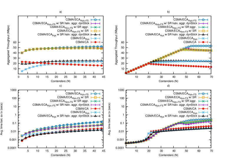
Figure 11a shows the average aggregated throughput of a saturated network with a channel error probability, (see Section IV-D). We can see that the highest throughput, corresponding to CSMA/ECA is lower than the one observed in a perfect channel (Figure 7a). Furthermore, curves with Schedule Reset (SR) seem to have lower aggregated throughput. This is because the backoff stage, and therefore the level of aggregation done by Fair Share, is repeatedly reduced.
Still assessing Figure 11a and focusing on the SR curves, we can see that both aggressive schedule halving with dynamic stickiness (SR aggr. halv. dynStick) curves (with and without Fair Share) have higher aggregated throughput than the rest (for a description of aggressive schedule halving and dynamic stickiness, refer to Algorithm 4 and Section III-G2). This Schedule Reset configuration reduces the time between successful transmissions (see Figure 11c) and maintains collision-free operation for longer periods of time thanks to the increase in the node’s stickiness.
Figure 11c shows the average time between successful transmissions for the same network setup. Even-though CSMA/ECA still has a higher metric than CSMA/CA due to the aggregation done by Fair Share, Schedule Reset is able of reducing this metric by almost .
Figure 11b and Figure 11d show the aggregated throughput and time between successful transmissions, respectively for a non-saturated network with the same . Since under non-saturated conditions CSMA/ECA nodes reset their schedule every time they empty their MAC queues, Schedule Reset’s benefits are not relevant. Nevertheless, a reduction in the time between successful transmissions is observed for Schedule Reset curves in Figure 11d.
VI Real hardware implementation
We confirmed the simulations results experimentally with a testbed of real prototypes. This phase was mandatory in order to check whether the behaviour of the system is still correct in the presence of real phenomena, like excessive channel errors, or technical limitations of the hardware like imperfect node synchronisation; and to verify the implementation feasibility of CSMA/ECA and the Schedule Reset mechanism with a real time horizon.
As CSMA/ECA works with the standard 802.11 PHY, we do not need the flexibility offered by complex development kits based on FPGAs like the WARP boards [36]. Any architecture that allows a customisation of the channel access delayblack would fit our requirements. For this reason we chose a widely available 802.11b/g WNIC from Broadcom. Like many other cards, its behaviour is ruled by a firmware code that controls the underlying hardware (including the radio, carrier sense and FIFOs) in real time. In particular we used the BRCM4318KBFG PCI card as it is supported by the OpenFWWF [25] open-source firmware, an alternative to the original code from the manufacturer that has been recently considered as development platform in several research projects [15, 37, 38, 39, 24].
Thanks to the extremely low price of this card (refurbished devices are widely available for less than each), it is possible to run experiments with very large testbeds. We used 25 PC-Engines Alix 2d2 nodes running Linux kernel 2.6.32 as stations and a more powerful computer with the same kernel as Access Point (AP), all nodes being equipped with the aforementioned WNIC.
We built on the DCF protocol implemented in OpenFWWF and adapted the firmware to create collision-free schedules as described in Algorithm 2. The modification was straightforward: for every transmitted data frame the firmware sets an ACK-time-out alarm. Later, either at the expiration of the timer or when the acknowledgment frame is received, it executes a handler labelled tx_contention_params_update. It updates the contention window value STATE_CW and backoff counter according to the success/failure of the previous transmission attempt, just as in Algorithm 2. Implementing CSMA/ECA required just a modification specifying that a reset of the backoff stage (or STATE_CW in this case) is performed only when a packet is dropped or when the MAC queue empties.
To incorporate stickiness into the prototype we added a STATE to the system that can be either STATE_DETERMINISTIC or STATE_RANDOM (related to the type of backoff being used), and a STICKINESS counter that we reset each time we have a success and decrement when failing. When the counter gets to zero we enter the random state. Upon a successful transmission we unconditionally enter the deterministic state and reset the stickiness counter to DEFAULT_STICKINESS.
For the Schedule Reset mechanism, we added a bitmap for monitoring the state of every single slot after a successful transmission. To index the current slot in the bitmap we used the hardware register SPR_IFS_BKOFFDELAY, which counts how many slots have still to come before the next transmission. The value of the register is decremented once per idle slot.
To avoid spurious detection, instead of continuously checking the state of the channel, we rely on the execution of the rx_plcp handler, which is called each time a valid PLCP is detected. When this happens, we implicitly know that the backoff counter has been frozen at least ago, which is the time between the detection of the first short trailing sequence and the complete decoding of the PLCP signal data. In any case, the slot is marked as busy.
We have the option to keep filling the bitmap for up to BITMAP_ROUND_BUILD consecutive successful transmissions ( in Section III-G) before checking if the central slot in the bitmap is available. If that is the case, the node’s current schedule is halved (a schedule halving, following Algorithm 4) and its stickiness is incremented to DEFAULT_STICKINESS.
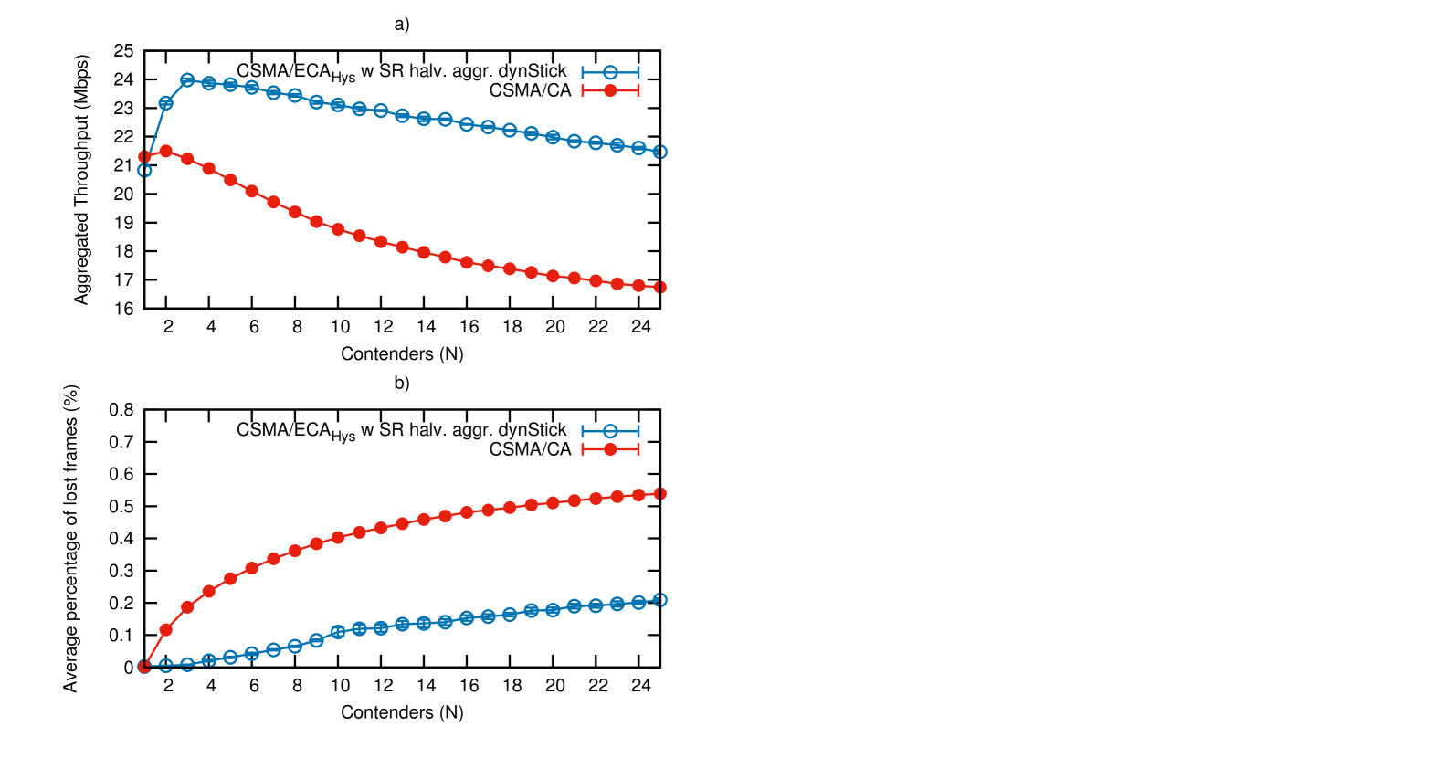
We performed four experiments for each tested number of contenders, starting from 1 and up to 25. For every experiment each station establishes an iPerf [40] session and transmits saturated UDP traffic towards a central AP, which also functions as iPerf server for each flow. We used WiFi channel 14 in order to avoid interference from other networks. The aggregated throughput is derived from the iPerf logs, while the percentage of lost frames is reported by the firmware. This is known to be ; where tx are the number of transmission attempts, and sx are the number of acknowledged frames.
Figure 12a shows the average aggregated throughput, while Figure 12b presents the average percentage of lost frames. Details of the testbed are shown in Table III.
CSMA/ECA has greater throughput due to its ability to avoid collisions more efficiently than CSMA/CA. Further, the Schedule Reset aggressiveness (see Section III-G2) prevents CSMA/ECA nodes from increasing too much the time between successful transmissions.
Nevertheless, the implementation results reveal that there are other underlying factors that disrupt collision-free schedules. This is evidenced by the increasing percentage of lost frames followed by a throughput degradation in CSMA/ECA. The analysis of the factors that may disrupt collision-free schedules on real hardware implementations of CSMA/ECA is left as future research.
| PHY | |
|---|---|
| Parameter | Value |
| PHY rate | 48 Mbps |
| Empty slot | |
| DIFS | |
| SIFS | |
| IEEE 802.11g WiFi channel | 14 |
| MAC | |
| Parameter | Value |
| Maximum backoff stage () | 5 |
| Minium Contention Window () | 16 |
| Maximum retransmission attempts | 6 |
| Data payload (Bytes) | 1470 |
| Schedule Reset | 1 |
| Schedule Reset mode | halving, dynStick |
| Default stickiness | 1 |
| TESTBED | |
| N | 25 |
| Distance between nodes and AP | 8 m |
| Arrangement of nodes | Semicircle |
VII Transitioning towards CSMA/ECA
The current PHY/MAC enhancements considered by the HEW Task Group seek to achieve higher throughput and include improved coding schemes; full duplex radios, capable of receiving and transmitting at the same time; OFDMA and Multiple-User Multiple-Input Multiple-Output (MU-MIMO), allowing the transmission of different packets to/from multiple destinations at the same time; as well as dynamic channel bonding techniques [41]. Using CSMA/ECA alongside these features would provide enhanced performance by constructing collision-free schedules, thus substantially decreblackasing the time spent recovering from collisions.
Additionally, there are several features and scenarios still to be analysed for CSMA/ECA networks. Part of what is left for future work is summarised in the following:
-
•
The performance of CSMA/ECA WLANs in dense scenarios: transmissions from stations in the same or other networks may negatively affect the collision-free operation, particularly when not all devices in the CSMA/ECA WLAN are able to listen such transmissions. As a consequence, not all stations will pause the backoff countdown accordingly, resulting in large slot drifts that disrupt any collision-free schedule, approximating CSMA/ECA performance to CSMA/CA’s.
-
•
Traffic differentiation: although priorities using different contention windows in CSMA/ECA proved to outperform CSMA/CA, other Enhanced Distributed Channel Access (EDCA) mechanisms like the Arbitration Inter-Frame Spacing (AIFS) would not work [42], whereas the following EDCA mechanisms would:
-
–
Transmission Opportunity (TXOP): stations with an increased TXOP are able to transmit more packets. APs in CSMA/ECA can use a big TXOP in order to transmit more than users.
-
–
Multiple Queues: [42] provides performance metrics for two traffic categories. In order to transition to CSMA/ECA a total of four access categories (AC) should be implemented, as in EDCA. Priorities to the multiple queues can be granted through different minimum and maximum contention windows.
CSMA/ECA with multiple access categories is expected to provide better traffic differentiation in WLANs, mainly due to the elimination of collisions by using a deterministic backoff after each access category’s successful transmission, as well as providing a minimum amount of transmission opportunities to each AC.
-
–
-
•
Coexistence with EDCA stations in the same WLAN.
VIII Conclusions
CSMA/ECA is able to construct a collision-free schedule with many contenders. Taking advantage of this condition, the cumulative throughput experienced by CSMA/ECA nodes goes beyond the achievable by CSMA/CA for any number of nodes. All of these while preserving throughput fairness. Further, as non-saturated CSMA/ECA networks get crowded the cumulative throughput keeps increasing up to the saturation point, contrary to the throughput degradation seen in CSMA/CA networks.
As CSMA/ECA is thought to be the next MAC for WLANs, coexistence with CSMA/CA nodes is paramount. Results show that coexistence is not an issue for any proportion of CSMA/ECA/CSMA/CA users. Moreover, when the network is composed with a majority of CSMA/ECA nodes, the cumulative throughput increases from CSMA/CA’s.
To top it all, the real hardware implementation of CSMA/ECA clearly outperforms CSMA/CA. In itself, the prototype represents a strong indicator that the proposed enhanced collision avoidance could be considered as a viable replacement or evolution of the current MAC for WiFi.
References
- [1] “IEEE Standard for Information Technology - Telecommunications and Information exchange between systems. Local and Metropolitan Area Networks - Specific requirements,” IEEE Std 802.11TM-2012, p. 1646, 2012.
- [2] Perahia, E, “IEEE 802.11n Development: History, Process, and Technology,” Communications Magazine, IEEE, vol. 46, no. 7, pp. 48–55, 2008.
- [3] G. Bianchi, “Performance Analysis of the IEEE 802.11 Distributed Coordination Function,” IEEE Journal on Selected Areas in Communications, vol. 18, no. 3, pp. 535–547, 2000.
- [4] V. Bharghavan, A. Demers, S. Shenker, and L. Zhang, “MACAW: a media access protocol for wireless LAN’s,” in ACM SIGCOMM Computer Communication Review, vol. 24, no. 4. ACM, 1994, pp. 212–225.
- [5] C. Wang, B. Li, and L. Li, “A new collision resolution mechanism to enhance the performance of IEEE 802.11 DCF,” IEEE Transactions on Vehicular Technology, vol. 53, no. 4, pp. 1235–1246, 2004.
- [6] F. Cali, M. Conti, E. Gregori, and P. Aleph, “Dynamic Tuning of the IEEE 802.11 Protocol to Achieve a Theoretical Throughput Limit,” vol. 8, no. 6, pp. 785–799, 2000.
- [7] A. Lopez-Toledo, T. Vercauteren, and X. Wang, “Adaptive Optimization of IEEE 802.11 DCF Based on Bayesian Estimation of the Number of Competing Terminals,” vol. 5, no. 9, p. 1283, 2006.
- [8] J. Barcelo, B. Bellalta, C. Cano, and M. Oliver, “Learning-BEB: Avoiding Collisions in WLAN,” in Eunice, 2008.
- [9] J. Barcelo, B. Bellalta, A. Sfairopoulou, C. Cano, and M. Oliver, “CSMA with Enhanced Collision Avoidance: a Performance Assessment,” in IEEE VTC Spring, 2009.
- [10] Y. He, R. Yuan, J. Sun, and W. Gong, “Semi-Random Backoff: Towards resource reservation for channel access in wireless LANs,” in 17th IEEE International Conference on Network Protocols. IEEE, 2009, pp. 21–30.
- [11] J. Barcelo, A. Toledo, C. Cano, and M. Oliver, “Fairness and Convergence of CSMA with Enhanced Collision Avoidance (ECA),” in 2010 IEEE International Conference on Communications (ICC), may 2010, pp. 1 –6.
- [12] M. Fang, D. Malone, K. Duffy, and D. Leith, “Decentralised learning MACs for collision-free access in WLANs,” Wireless Networks, vol. 19, pp. 83–98, 2013. [Online]. Available: http://dx.doi.org/10.1007/s11276-012-0452-1
- [13] K. Hui, T. Li, D. Guo, and R. Berry, “Exploiting peer-to-peer state exchange for distributed medium access control,” in Information Theory Proceedings (ISIT), 2011 IEEE International Symposium on. IEEE, 2011, pp. 2368–2372.
- [14] J. Barcelo, B. Bellalta, C. Cano, A. Sfairopoulou, and M. Oliver, “Towards a Collision-Free WLAN: Dynamic Parameter Adjustment in CSMA/E2CA,” in EURASIP Journal on Wireless Communications and Networking, 2011.
- [15] I. Tinnirello, G. Bianchi, P. Gallo, D. Garlisi, F. Giuliano, and F. Gringoli, “Wireless MAC processors: Programming MAC protocols on commodity Hardware,” in INFOCOM, 2012 Proceedings IEEE, march 2012, pp. 1269 –1277.
- [16] L. Sanabria-Russo, A. Faridi, B. Bellalta, J. Barceló, and M. Oliver, “Future Evolution of CSMA Protocols for the IEEE 802.11 Standard,” in 2nd IEEE Workshop on Telecommunications Standards: From Research to Standards. Budapest, Hungary, 2013.
- [17] IEEE 802.11 TGax, “Status of IEEE 802.11 HEW Task Group,” http://www.ieee802.org/11/Reports/tgax_update.htm, 2014.
- [18] B. Bellalta, “IEEE 820.11 ax: High-Efficiency WLANs,” IEEE Wireless Communications (arXiv preprint arXiv:1501.01496), Accepted July 2015.
- [19] G. Martorell, F. Riera-Palou, G. Femenias, J. Barcelo, and B. Bellalta, “On the performance evaluation of CSMA/E2CA protocol with open loop ARF-based adaptive modulation and coding,” European Wireless. 18th European Wireless Conference, pp. 1 –8, april 2012.
- [20] E. Yucesan, C. Chen, J. Snowdon, and J. Charnes, “COST: A component-oriented discrete event simulator,” in Winter Simulation Conference, 2002.
- [21] L. Sanabria-Russo, J. Barcelo, A. Faridi, and B. Bellalta, “WLANs throughput improvement with CSMA/ECA,” in 2014 IEEE Conference on Computer Communications Workshops (INFOCOM WKSHPS), April 2014, pp. 125–126.
- [22] L. Sanabria-Russo, J. Barcelo, and B. Bellalta, “Prototyping Distributed Collision-Free MAC Protocols for WLANs in Real Hardware,” in Multiple Access Communcations. Springer International Publishing, 2013, pp. 82–87.
- [23] L. Sanabria-Russo. (2013) Report: Prototyping Collision-Free MAC Protocols in Real Hardware. Webpage. [Online]. Available: http://luissanabria.me/written/beca-test1.pdf
- [24] L. Sanabria-Russo, F. Gringoli, J. Barcelo and B. Bellalta. (2014) Implementation and Experimental Evaluation of a Collision-Free MAC Protocol for WLANs. Arxiv pre-print. [Online]. Available: http://arxiv.org/pdf/1410.7924v1
- [25] F. Gringoli and L. Nava. Open Firmware for WiFi Networks. Webpage. [Online]. Available: http://www.ing.unibs.it/openfwwf/
- [26] L. Hanzo, H. Haas, S. Imre, D. O’Brien, M. Rupp, and L. Gyongyosi, “Wireless Myths, Realities, and Futures: From 3G/4G to Optical and Quantum Wireless,” Proceedings of the IEEE, vol. 100, no. Special Centennial Issue, pp. 1853–1888, 2012.
- [27] C. Cano and D. J. Leith, “Coexistence of WiFi and LTE in Unlicensed Bands: A Proportional Fair Allocation Scheme,” IEEE International Conference on Communications Workshops, 2015. ICC Workshops 2015.
- [28] M. Fang, D. Malone, K. Duffy, and D. Leith, “Decentralised learning MACs for collision-free access in WLANs,” Wireless Networks, pp. 1–16, 2010.
- [29] J. Lee and J. C. Walrand, “Design and nalysis of an asynchronous zero collision MAC protocol,” arXiv preprint arXiv:0806.3542, 2008.
- [30] D. Skordoulis, Q. Ni, H.-H. Chen, A. Stephens, C. Liu, and A. Jamalipour, “IEEE 802.11n MAC Frame Aggregation Mechanisms for Next-Generation High-Throughput WLANs,” Wireless Communications, IEEE, vol. 15, no. 1, pp. 40–47, February 2008.
- [31] L. Sanabria-Russo. (2014) Github repository: CSMA-ECA-bounds-example. Webpage, accessed October 2014. [Online]. Available: https://github.com/SanabriaRusso/CSMA-ECA-bounds-example
- [32] W. Gong and D. Malone, “Addressing Slot Drift in Decentralized Collision Free Access Schemes for WLANs,” in Multiple Access Communications, ser. Lecture Notes in Computer Science, B. Bellalta, A. Vinel, M. Jonsson, J. Barcelo, R. Maslennikov, P. Chatzimisios, and D. Malone, Eds. Springer Berlin Heidelberg, 2012, vol. 7642, pp. 146–157. [Online]. Available: http://dx.doi.org/10.1007/978-3-642-34976-8\_16
- [33] J. Deng, B. Liang, and P. K. Varshney, “Tuning the carrier sensing range of IEEE 802.11 MAC,” in Global Telecommunications Conference, 2004. GLOBECOM’04. IEEE, vol. 5. IEEE, 2004, pp. 2987–2991.
- [34] B. Jang and M. L. Sichitiu, “IEEE 802.11 saturation throughput analysis in the presence of hidden terminals,” IEEE/ACM Transactions on Networking (TON), vol. 20, no. 2, pp. 557–570, 2012.
- [35] L. Sanabria-Russo, J. Barcelo, and B. Bellalta. (2015) Implementing CSMA/ECA in COST. [Online]. Available: https://github.com/SanabriaRusso/CSMA-ECA-HEW
- [36] K. Amiri, Y. Sun, P. Murphy, C. Hunter, J. R. Cavallaro, and A. Sabharwal, “WARP, a Modular Testbed for Configurable Wireless Network Research at Rice,” IEEE SWRIF, 2007.
- [37] P. Salvador, V. Mancuso, F. Gringoli, and A. Banchs, “VoIPiggy: Analysis and Implementation of a Mechanism to Boost Capacity in IEEE 802.11 WLANs Carrying VoIP Traffic,” IEEE Transactions on Mobile Computing, vol. 7, no. 13, 2014.
- [38] P. Salvador, L. Cominardi, F. Gringoli, and P. Serrano, “A first implementation and evaluation of the IEEE 802.11aa group addressed transmission service,” Computer Communication Review, vol. 44, no. 1, 2014.
- [39] D. Berger, F. Gringoli, N. Facchi, I. Martinovic, and J. Schmitt, “Gaining Insight on Friendly Jamming in a Real-world IEEE 802.11 Network,” in Proceedings of the ACM Conference on Security and Privacy in Wireless & Mobile Networks, 2014.
- [40] A. Tirumala, F. Qin, J. Dugan, J. Ferguson, and K. Gibbs, “Iperf: The TCP/UDP bandwidth measurement tool,” http://dast.nlanr.net/Projects, 2005.
- [41] B. Bellalta, A. Faridi, J. Barcelo, A. Checco, and P. Chatzimisios, “Channel Bonding in Short-Range WLANs,” in European Wireless 2014; Proceedings of 20th European Wireless Conference, May 2014, pp. 1–7.
- [42] J. Barcelo, B. Bellalta, C. Cano, A. Sfairopoulou, M. Oliver, and J. Zuidweg, “Traffic Prioritization for Carrier Sense Multiple Access with Enhanced Collision Avoidance,” in IEEE International Conference on Communications Workshops, 2009. ICC Workshops 2009., June 2009, pp. 1–5.