Compact, robust, and spectrally pure diode-laser system with a filtered output and a tunable copy for absolute referencing
Abstract
We report on a design of a compact laser system composed of an extended cavity diode laser with high passive stability and a pre-filter Fabri-Perot cavity. The laser is frequency stabilized relative to the cavity using a serrodyne technique with a correction bandwidth of MHz and a dynamic range of MHz. The free running laser system has a power spectral density (PSD) Hz2/Hz centered mainly in the acoustic frequency range. A highly tunable, GHz copy of the spectrally pure output beam is provided, which can be used for further stabilization of the laser system to an ultra-stable reference. We demonstrate a simple one-channel lock to such a reference that brings down the PSD to the sub-Hz level. The tuning, frequency stabilization and sideband imprinting is achieved by a minimum number of key elements comprising a fibered EOM (electro-optic modulator), AOM (acousto-optic modulator) and a NLTL (non-linear transmission line). The system is easy to operate, scalable, and highly applicable to atomic/molecular experiments demanding high spectral purity, long-term stability, and robustness.
1 Introduction
Stable and spectrally pure lasers have widespread applications in optical frequency standards Diddams2001 , measurement of fundamental constants Wineland2010 ; Marion2003 ; Eisele_gravity , gravitational-wave detection Abbott2009 , quantum information Schindler2013 , high-resolution spectroscopy Kolachevsky2011 as well as stimulated adiabatic transfer of population between atomic/molecular levels Danzl2008 ; Ni2008 ; Mark2009 ; Danzl2010a ; Aikawa2011a ; Takekoshi2014 . It has already been demonstrated that the laser frequency can be locked to better than Hz precision relative to a reference Fabri-Perot (FP) cavity. The ultimate linewidth achieved is then limited by the cavity’s mechanical vibrational and thermal noise. Recently a linewidth of mHz was demonstrated by stabilizing a erbium-doped fiber laser to a silicon single-crystal Fabri-Perot cavity held at cryogenic temperatures Kessler2012 .
Diode lasers are generally compact and cost effective, cover wide spectral ranges, can be tuned to the desired wavelength, and can be optically narrowed. For an extended cavity diode laser (ECDL) with the usual grating feedback the linewidth easily narrows to the kHz range Riehle2004 . To further reduce the linewidth additional optical feedback from an external cavity Breant1989 can be employed, combined with a low frequency electronic lock to a reference cavity (RC) Kirilov2009 . The optical lock is difficult to maintain since one has to stabilize the “half-cavity” between the ECDL and the optical feedback FP. Different variations to stabilize and increase the dynamic range of the optical lock include balanced polarization-sensitive methods or dithering of the half-cavity path Doringshoff2007 ; Labaziewicz2007 . For absolute frequency reference and additional noise reduction the RC spacer is fabricated out of ULE (Corning), Zerodur, or single-crystal silicon substrates, and the laser is stabilized at the zero crossing of the spacer’s thermal expansion coefficient. The error signal from referencing the laser to the RC is generated using the Pound-Drever-Hall (PDH) technique Black2001 . In almost all scenarios for tuning the laser frequency in the range of the free spectral range (FSR) of the RC a configurations of at least 2 double-pass AOMs has to be employed.
As an alternative to external cavity optical feedback one can lengthen the cavity length of the ECDL Kolachevsky2011 , since the linewidth depends inversely quadratically on the length as , where is the optical length of the laser diode (LD). In addition, the laser is typically locked to a RC with a high bandwidth (BW) electronic lock. The mode-hop free tunability is then compromised relative to a short cavity setup. Typically in most designs the slow integrated correction signal is applied to the piezo element (PZT) regulating the ECDL cavity length and the fast signal is applied to the injection current of the laser diode. The fast channel BW is typically limited to MHz due to competing thermal and electronic charge carrier effects with opposite signs of , where is the laser wavelength and is the diode injection current. This is specific to the respective laser diode and requires that one individually adapts the design of the proportional-integral-derivative (PID) servo. In some of the above designs the useful output sent to the experiment is taken in transmission through a pre-stabilizing filter cavity (FC) (which could be the same one providing the optical feedback Labaziewicz2007 ) to erase the remaining noise pedestal due to stochastic laser phase modulation, which typically caries about of the laser power and whose width MHz and shape depend crucially on the PID parameters Matveev2008 ; yatsenko2014 .
Here we present a diode-laser system that is extremely robust to acoustic perturbations and that has superior long-term stability with high modularity suitable for various demanding applications. The linewidth narrowing is accomplished by a method independent of the specific laser diode. The continuous tunability of the laser without feed-forward Petridis2001 is GHz. We employ a low-acoustically susceptible mechanical design of an ECDL in Littrow configuration in combination with a high BW and dynamic range fibered EOM-NLTL Kohlhaas2012 ; Afshari2005 ; Johnson2010a , a single doubly-diffracting AOM, and a FC, each contributing both to the tuning and stabilization of the laser. The setup can be used in many different, more familiar configurations that are easily interchangeable from the one described in this work, where the roles of the components are disentangled, similar but still superior to standard laser systems, with the cost of adding additional infrastructure. The passive stability of the ECDL combined with the features of the above elements provides an economic and elegant solution to a high performance laser system and a good alternative to existing designs.
2 Basic description of the laser system. Advantages of the design
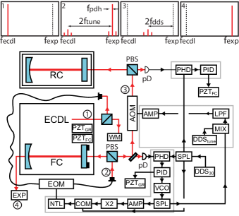
The rough scheme is presented on Fig.1. The output of the ECDL is passed through a fibered EOM driven by the superposition of a direct digital synthesizer’s (DDS) sinusoidal output at fixed frequency and a sawtooth signal generated by a NLTL powered by a frequency-doubled broadband high-bandwidth voltage-controlled oscillator (VCO) at (the factor of 2 results from a doubling stage after the VCO; see below). Most of the light entering the EOM at frequency is diffracted into the upper (or lower, but not both; a property of the serrodyne modulation technique Johnson2010a , details in sec.3) sideband at . The spectral distribution after the EOM is composed of mostly and a small leftover at with both frequencies accompanied by their small sidebands at (panel 1 of Fig.1). Further the light is directed towards a 2-port tunable FC (tuning is possible by a PZT) that is resonant with . The laser is locked to the FC using a PDH lock at by slow/fast lock sent to the ECDL-PZT/EOM-NLTL respectively. In transmission the filtered light goes to the experiment with frequency (panel 4 of Fig.1). In reflection the light consists now of mostly and a leftover at (the last portion results from the non-perfect mode matching and mirror losses). A small portion of it is necessary for the PDH lock (using the lines at ), but the rest is passed through a double-pass up-shifting AOM. The AOM is driven by the frequency difference , where the first portion comes from the same VCO driven by the fast port of the PID used to lock to the FC, but before the doubling stage, (Fig.1; denoted X2) and the second from a DDS (subtracted using a rf mixer; denoted MIX). The useful light after the double-pass AOM has the frequency (panel 3 of Fig.1). The result is a filtered, ultra-tightly locked main beam coming in transmission of the FC with noise dominated only by the cavity’s acoustics, and another beam (the one after the AOM) that is shifted away, which, in the acoustic frequency range, perfectly resembles the primary one. The latter one can be used to lock the whole system to an ultimate RC by a simple one channel PID with mediocre bandwidth, addressing the PZT of the FC.
The system’s advantages apart from the above mentioned ones over the standard realizations of such systems include: 1) extremely high BW and dynamic range of the fibered EOM-NLTL system superior to intra-cavity EOMs (which have smaller dynamic range) or injection current locks (which have smaller BW and dynamic range and add amplitude noise), 2) comparatively low optical losses (mainly due to the NLTL), 3) convenient long-range tuning without the need to optimize AOMs when switching to another atomic or molecular line as one simply has to change the DC value and accordingly to be in the convenient range of the AOM (the fast lock to the EOM is ac-coupled starting from Hz), 4) decreased complexity by a) achieving tuning, sideband modulation, and locking (to both FC and RC) by just one EOM and one AOM, b) powering all the components by dBm rf amplifiers (still in the power range where the costs are minimal), and c) using only one actuator, namely the FC PZT, to lock to the RC in view of its high BW (a small mirror is used and a carefully chosen PZT), and 5) filtered output by the FC, eliminating stochastic laser noise and unwanted sidebands.
3 ECDL engineering and performance
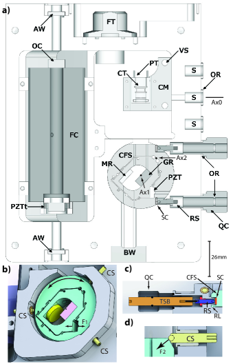
We first discuss the laser housing and mount in detail. It is based on a Littrow-type ECDL with a variable cavity length in the range of cm. The passive stability of the ECDL (operating with a laser diode EYP-RWE-1060, Eagleyard) and acoustic immunity are improved in comparison to standard designs by a few simple measures (Fig.2). First, a commercial diode collimation tube (LT230P-B, Thorlabs) is partially flattened on two parallel planes and sandwiched between two Peltier elements (TE-17-1.0-2.0, TE tech.) to control the diode’s temperature using a k thermistor (Vishay BCComponents). The overall square-shaped mount (CM) serves as a heat sink and as a vertical goniometer. Rotation in the vertical plane (around axis Ax0) is necessary to optimize the optical feedback. It is initiated by vertical precision screws (VS) pressing against the floor of the main body. Once aligned, the vertical rotation degree of freedom is frozen by tightening the CM to the sidewall of the laser body Cook2012 as it is not used in a daily operation. Its contribution therefore to the acoustic noise of the laser is minimized. The grating (holographic, number of lines/mm chosen such that ; 33025FL01-239H Richardson gratings) is positioned in a cylinder-flexure structure (CFS) that is allowed to rotate only in the horizontal plane for tuning the wavelength (around Ax1) Toptica . Rough tuning is achieved by a rotation induced by two fine threaded screws (RS) (F3SS10 and N250L3P, Thorlabs) inducing rotation in opposite directions by pushing along the tangent of the CFS (see Fig.2 a) and c) for horizontal and vertical views respectively). The screws have ball tips and press against the CFS through two sapphire crystals (SC, 43-627, Edmund). Smooth rotation is accomplished by three ball-tip precise screws (CS) that press the upper edge of the cylinder, which is wedged at (Fig.2 d)). This feature also assures that the screws apply a normal downward force component to the cylinder (F2), therefore guaranteeing rotation only in the horizontal plane. The CFS contacts the main body only through the ball tips of the three CS and a thin 1 mm wide ring-shaped lip left on the outer edge of its bottom surface (denoted RL and visible in Fig.2 c)). After choosing the rough wavelength the horizontal rotation is also frozen (by applying a force on the CFS by both RS). Subsequent fine tuning is left to a PZT stack (PCh 150/7x7/2, Piezomechanik) driving only the flexure (force F1 on Fig.2 b) ), designed to have a mechanical frequency at kHz. The center of the grating moves m for N force applied by the PZT. During flexing the grating experiences a rotation around Ax2. The CFS is made out of 316 SS. Modeling of the above properties is achieved using a standard CAD program with an elastic properties simulation capability. In practice the resonant frequency is determined by exciting the PZT and sweeping a variable sound generator while observing the noise spectral density of the laser when locked to the FC. The whole body of the laser is made out of aluminum and is vacuum sealed, allowing it to be evacuated if desired. It is thermally stabilized by 4 Peltier elements (TE-127-1.0-1.3, Tetech.) wired in series. The resistive bridges for both the diode and laser body are attached on the back of the laser for thermal stability and share the layout with the LD filtering circuit. Rough tuning is possible by engaging the two finely threaded screws RS with adapted quick-seal connects QC (B-025-K, Lesker), which allows for rotation without breaking vacuum (applying Apiezon vacuum grease on the sealing o-rings experiencing the rotation driven by transmission-seal bar (TSB) from outside). The chamber is evacuated through a small inlet (same as V1021-1, DLH Industries) machined on a KF25 flange, which is economic and does not take much space compared to standard vacuum valves.
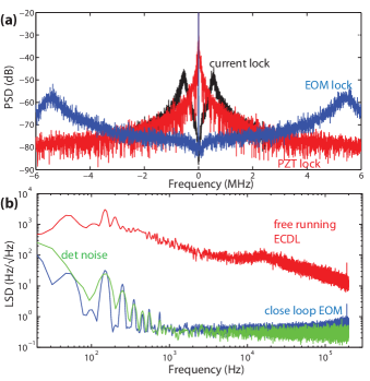
The performance of the bare, free-running ECDL without engaging the tight locks to the FC and the RC is characterized by analyzing the frequency noise linear spectral density (LSD) of the error signal as shown in Fig.3 when the laser is locked to the FC using only the slow (Hz) servo branch applied to the PZT behind the grating of the ECDL (the feedback via the EOM is not applied). There are no visible mechanical resonances. The “fast” linewidth of the laser is kHz mostly defined by the length of the ECDL cavity. At Fourier frequencies kHz the spectrum increases from the quantum white noise level due to additional technical noise sources. The overall rms linewidth is kHz. The corresponding Allan deviation calculated based on the PSD is in the kHz range for times in the s - ms interval.
4 Full laser system description and performance
We now use the fibered EOM (EOspace, PM-0K5-10-PFA-PFA-980, 10 GHz BW) as a fast actuator. Almost of the light is coupled into the EOM, additionally spatially filtering the beam and thus delivering a clean Gaussian mode. We note that one typically filters the laser mode with a polarization maintaining (PM) fiber; the presence of the fibered EOM therefore eliminates this step. The light is then directed to the plano-convex FC (finesse , FSR GHz, spacer made of Zerodur square block 30x30x100 mm, Helma optics) with one coupler (both couplers from Layertec, low loss, 12.5 mm diam.; flat and mm radius) mounted on two concentric tubular PZT’s (Meggit, F3270154, F3270055) compensating their thermal drifts (Fig.2; PZTt). The FC is placed in a V-groove and held in place by 8 viton O-rings ( mm OD) positioned closely under and above the diagonal-mid plane (top clamps visible on Fig.2). Almost of the light is coupled into the FC on resonance. The EOM is driven by a NLTL 7013 (Tactron Inc., produced by Picosecond Pulse Inc., operating range MHz, higher than the specifications), which converts the signal from the VCO (VCO ROS-625-219+, Mini-Circuits) into a sawtooth-shaped signal Johnson2010a . When Fourier transformed the signal of the NLTL driven at frequency is composed of a comb of frequencies with power scaling roughly as , where is the Fourier index. Once the amplitude of the sawtooth signal becomes equal to the voltage of the EOM (i.e. 3-4 V), the modulated phase has an effectively linear time dependence and therefore most of the light power () is diffracted either into the upper or into the lower sideband spaced at (500-1300 MHz) away from the carrier. This sideband can be tuned with dB BW of MHz limited by the VCO BW and with a dynamic range of MHz. This allows for an extremely fast and easy to operate lock with a closed loop BW that can be pushed to MHz, limited primarily by phase delays in the PID (see Fig.4 a) and c) for a schematic) and cable length.
The FC is positioned in the same body as the ECDL to minimize space and costs. The whole chamber is covered with silicon (Smooth-on Mold Max 15T) for damping acoustic air-born noise Cook2012 . The sidebands needed for the PDH lock are imprinted by a -MHz wave provided by a fixed DDS (AD9858) right before the NLTL (power splitters resp. combiners are ADP-2-20-75, Mini-Circuits). These sidebands pass the NLTL unaltered. One could perform the mixing after the NLTL with a resistive combiner, but then a dB loss is added and the of the EOM can barely be reached. In reflection of the light is used for the PDH to the FC. The fast correction is applied to the voltage-controlled port of the VCO. The slow correction ( Hz) goes to the grating piezo (PZT) of the ECDL. At this point the laser is locked to sub-Hz linewidth relative to the FC and the PSD is dominated solely by the FC’s acoustic noise. Fig.3 a) and b) compare the PSD/LSD of the error signal to the FC for the free running ECDL and in a locked configuration. For comparison we show the PSD when using the injection current of the LD as a fast actuator. We reach a unity gain frequency of MHz for the servo loop when locking via the current without lead compensation. Sending the fast correction to the fibered EOM effortlessly achieves unity gain frequencies that could be pushed to MHz. For low frequencies the noise cancellation is more than dB.
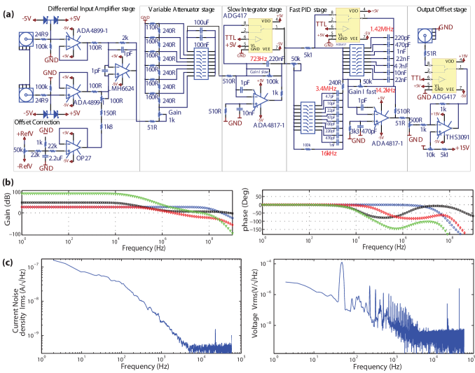
To achieve such high BW a careful design of the PID circuit is needed. In Fig.4 a) we provide the schematic and describe the most important features. The differential input amplifier stage consists of two unity gain buffers (ADA4899-1, MHz GBWP, LSD) and a subtracting high BW amplifier (LMH6624, GHz GBWP, LSD) with a fixed voltage gain of dB. This configuration ensures a high input impedance optimal for signals coming from phase-detectors and a high usable signal BW while keeping the overall noise level low. Next a variable attenuator stage allows for a reduction of gain if necessary. Additionally one can choose between AC and DC coupling of the signal (corner frequency Hz). The first (slow) integrator stage has a fixed corner frequency of kHz. The maximum voltage gain for low frequencies reaches dB, the gain in the proportional region is fixed to dB. The amplifier that we use (ADA4817-1, GHz GBWP, LSD) has FET-input stages, ensuring negligible changes in the offset voltage in the whole integral gain region. The full PID stage, using the same amplifier as the slow integrator stage, uses DIP-switches to set the corner frequencies of the D- and I-part by changing the corresponding capacitances. The P-part has a fixed attenuation of dB, ensuring that the D-part with a maximum of dB gain is within a frequency region where the bandwidth of the amplifier is no limitation. The available corner frequencies of the I-part with a maximum gain of dB are limited to low frequencies such that no overlap with the first (slow) integrator could lead to instabilities due to high phase shifts. A full-scale output offset can be added within the last stage (THS3091, MHz Bandwidth, LSD), which also serves as an output buffer able to provide up to mA current.
Overall, all electronic parts, especially the amplifiers, are chosen carefully to allow a maximum electronic bandwidth of several tens of MHz such that phase shifts due to the amplifiers of the PID circuit are negligible in the overall PID, thereby not limiting the feedback BW. Bode plots showing the performance of our circuitry are given in Fig. 4. To minimize electronic noise introduced by the PID, ultra-low-noise amplifiers and small resistor values to reduce thermal noise are used. The current and PZT driver circuits are also home made with noise figures of ( @ kHz) for the current and ( @ kHz) for the piezo in the Hz - kHz range (see Fig. 4 c)).
Next, for better absolute stability, we reference the laser to a highly stable RC without any additional components other than a single AOM (Fig.1). A DC voltage in the range of about V is added to the correction signal of the PID to tune the laser to a desired average position relative to the carrier . The light reflected from the FC contains non-diffracted light at the frequency of the ECDL carrying sidebands at MHz (see panel 2 of Fig.1). Note that this light still has the noise of the ECDL. It is passed through a double-pass up-diffracting AOM (Crystal Technology, model 3200, 200 MHz center frequency). The AOM is driven by a portion of the radio-frequency signal that comes from the VCO and that is mixed with the signal at from a DDS, resulting in an approximately -MHz drive within the range of the AOM ( is chosen accordingly). The AOM is not a part of the closed loop but since it is driven by the radio-frequency that contains the frequency excursions of the ECDL relative to the FC, it corrects the frequency excursions within its bandwidth. The light after the AOM is shifted by with respect to the light transmitted through the FC (see panel 3 of Fig.1). In comparison to the FC-transmitted beam it has enhanced noise beyond the AOM’s bandwidth (which is typically kHz). This, however, is irrelevant to the lock to the RC as the only noise that needs to be compensated for comes from the acoustic noise of the FC.
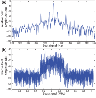
In Fig.5 we analyze the light that comes out of the AOM. We show the beat signal between the light locked to and transmitted through the FC and the light diffracted by the AOM when the AOM is either driven by an independent source or driven by the signal that is correlated with the signal that is fed to the EOM. When the AOM is driven from a fixed -MHz source the beat as shown in Fig.5 b) reveals the linewidth of the free running ECDL (over the time of the sweep of s). When driven by the half frequency of the EOM at MHz the beat signal dramatically narrows as shown in Fig.5 a). We attribute the spurs at multiples of 50 Hz visible in Fig.5 a) to the power supply that drives the LD current source and the PZT drivers (see Fig. 4 c)). With appropriate filtering, they could be removed.
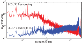
With the feedback to the AOM the diffracted light can now be sent to the RC. A single-channel feedback to the fast PZT of the FC (PZTt in Fig.1) eliminates the acoustic noise of the FC and provides long-term stability. The light after the AOM already carries PDH-sidebands, eliminating the need for an additional EOM. In Fig.6 we compare the LSD of the PDH-signal of the free-running ECDL/FC-system to that of the ECDL/FC-system locked to the RC (cylindrical ULE cavity in vacuum at Torr with finesse ). Even without the lock to the RC the free running ECDL/FC laser linewidth as calculated from the LSD is already Hz and, as expected, the LSD is significant only in the acoustic range. When locked the acoustic noise is greatly reduced. The laser linewidth relative to the RC is now sub-Hz, although this estimate is based purely on the LSD of the PDH error signal and does not include a possible residual amplitude modulation (RAM) at the PDH frequency. Choosing a smaller (i.e. lighter) cavity mirror and a FC PZT with a smaller inner diameter we expect to be able to increase the BW of the second lock to at least kHz and not be limited by the mechanical resonance of the FC PZT-mirror Briles2010 that can still be seen in the error-signal spectrum.
5 Conclusions
In conclusion, we have demonstrated a simple, compact, and versatile laser system that is easy to operate and that achieves simultaneously high spectral purity, high tunability, long-term stability, and robustness. It should facilitate experiments in high precision spectroscopy, meteorology, interferometry, and quantum state control. We note that this locking scheme does not involve electronic feedback to the laser diode itself. Laser diodes and fibered EOMs cover a large portion of the visible and near-infrared spectrum of interest for many experiments in atomic and molecular physics, making the setup widely applicable. The fibered EOM’s highly defined interaction region within the crystal makes the system less susceptible to problems arising from crystal inhomogeneity or anisotropy of the applied field Kessler2012 . One can also use the EOM for canceling RAM by simply feeding a DC offset on top of the rf correction signal Wong1985 . An ultimate test for our system would be a beat measurement involving two identical systems locked to independent ultra-stable reference cavities. Our system will first be applied to molecular ground-state transfer on KCs molecules similar to work presented in Ref.’s Danzl2008 ; Ni2008 ; Mark2009 ; Danzl2010a ; Aikawa2011a ; Takekoshi2014 .
6 Acknowledgments
We thank J. Berquist for providing the ULE cavity, J. Danzl for helping with the design of the PID circuit, and K. Aikawa for useful suggestions on the manuscript. We acknowledge generous support by R. Grimm. The work is supported by the European Research Council (ERC) under Project No. 278417.
References
- (1) S. A. Diddams, T. Udem, J. C. Bergquist, E. A. Curtis, R. E. Drullinger, L. Hollberg, W. M. Itano, W. D. Lee, C. W. Oates, K. R. Vogel, and D. J. Wineland, An optical clock based on a single trapped 199Hg+ ion. Science 293, 825–828 (2001)
- (2) C. W. Chou, D. B. Hume, T. Rosenband, and D. J. Wineland, Optical clocks and relativity. Science 329, 1630–1633 (2010)
- (3) H. Marion, F. Pereira Dos Santos, M. Abgrall, S. Zhang, Y. Sortais, S. Bize, I. Maksimovic, D. Calonico, J. Grünert, C. Mandache, P. Lemonde, G. Santarelli, P. Laurent, A. Clairon, and C. Salomon, Search for variations of fundamental constants using atomic fountain clocks. Phys. Rev. Lett. 90, 150801 (2003)
- (4) C. Eisele, A. Y. Nevsky, and S. Schiller, Laboratory test of the isotropy of light propagation at the level. Phys. Rev. Lett. 103, 090401 (2009)
- (5) B. P. Abbott, LIGO: The laser interferometer gravitational-wave observatory. Rep. Prog. Phys. 72, 076901 (2009)
- (6) P. Schindler, D. Nigg, T. Monz, J. T. Barreiro, E. Martinez, S. X. Wang, S. Quint, M. F. Brandl, V. Nebendahl, C. F. Roos, M. Chwalla, M. Hennrich, and R. Blatt, A quantum information processor with trapped ions. New Journal of Physics 15, 123012 (2013)
- (7) N. Kolachevsky, J. Alnis, C. G. Parthey, A. Matveev, R. Landig, and T. W. Hänsch, Low phase noise diode laser oscillator for 1S-2S spectroscopy in atomic hydrogen. Opt. Lett. 36, 4299–4301 (2011)
- (8) J. G. Danzl, E. Haller, M. Gustavsson, M. J. Mark, R. Hart, N. Bouloufa, O. Dulieu, H. Ritsch, and H.-C. Nägerl, Quantum gas of deeply bound ground-state molecules. Science 321, 1062 (2008)
- (9) K.-K. Ni, S. Ospelkaus, M. H. G. de Miranda, A. Pe’er, B. Neyenhuis, J. J. Zirbel, S. Kotochigova, P. S. Julienne, D. S. Jin, and J. Ye, A high phase-space-density gas of polar molecules. Science 322, 231 (2008)
- (10) M.J. Mark, J.G. Danzl, E. Haller, M. Gustavsson, N. Bouloufa, O. Dulieu, H. Salami, T. Bergeman, H. Ritsch, R. Hart, and H.-C. Nägerl, Dark resonances for ground-state transfer of molecular quantum gases. Appl. Phys. B 95, 219–225 (2009)
- (11) J. G. Danzl, M. J. Mark, E. Haller, M. Gustavsson, R. Hart, J. Aldegunde, J. M. Hutson, and H.-C. Nägerl, An ultracold high-density sample of rovibronic ground-state molecules in an optical lattice. Nature Phys. 6, 265–270 (2010)
- (12) K. Aikawa, J. Kobayashi, K. Oasa, T. Kishimoto, M. Ueda, and S. Inouye, Narrow-linewidth light source for a coherent Raman transfer of ultracold molecules. Opt. Express, 19 14479–14486 (2011)
- (13) T. Takekoshi, L. Reichsöllner, A. Schindewolf, J. M. Hutson, C. R. Le Sueur, O. Dulieu, F. Ferlaino, R. Grimm, and H.-C. Nägerl, Ultracold dense samples of dipolar RbCs molecules in the rovibrational and hyperfine ground state Phys. Rev. Lett. 113, 205301 (2014)
- (14) T. Kessler, C. Hagemann, C. Grebing, T. Legero, U. Sterr, F. Riehle, M. J. Martin, L. Chen, and J. Ye, A sub-40-mHz-linewidth laser based on a silicon single-crystal optical cavity. Nature Photonics 6, 687–692 (2012)
- (15) F. Riehle, Frequency Standards. Wiley VCH Verlag (2004)
- (16) C. H. Breant, Frequency noise analysis of optically self-locked diode lasers. IEEE J. Quantum Elect. 25, 1131–1142 (1989)
- (17) E. Kirilov and S. Putterman, 2-Photon ionization for efficient seeding and trapping of strontium ions. European Phys. J. D 54, 683–691 (2009)
- (18) K. Döringshoff, I. Ernsting, R.-H. Rinkleff, S. Schiller, and A. Wicht, Low-noise, tunable diode laser for ultra-high-resolution spectroscopy. Opt. Lett. 32, 2876–2878 (2007)
- (19) J. Labaziewicz, P. Richerme, K. R. Brown, I. L. Chuang, and K. Hayasaka, Compact, filtered diode laser system for precision spectroscopy. Opt. Lett. 32, 572–574 (2007)
- (20) E. D. Black, An introduction to Pound-–Drever–-Hall laser frequency stabilization, Am. J. Phys. 69, 79–87 (2001)
- (21) A. N. Matveev, N. N. Kolachevsky, J. Alnis, and T. W. Hänsch, Spectral parameters of reference-cavity-stabilised lasers. Quantum Electron. 38, 391–400 (2008)
- (22) L. P. Yatsenko, B. W. Shore, and K. Bergmann, Detrimental consequences of small rapid laser fluctuations on stimulated Raman adiabatic passage. Phys. Rev. A 89, 013831 (2014)
- (23) C. Petridis, I. D. Lindsay, D. J. M. Stothard, and M. Ebrahimzadeh, Mode-hop-free tuning over 80 GHz of an extended cavity diode laser without antireflection coating. Rev. Sci. Instrum. 72, 3811–3815 (2001)
- (24) R. Kohlhaas, T. Vanderbruggen, S. Bernon, A. Bertoldi, A. Landragin, and P. Bouyer, Robust laser frequency stabilization by serrodyne modulation. Opt. Lett., 37, 1005–1007 (2012)
- (25) E. Afshari, S. Member, and A. Hajimiri, Nonlinear transmission lines., IEEE J. Solid-St. Circ. 40, 744–752 (2005)
- (26) A commercial ECDL design based on a flexture design is available by the company Toptica (patents DE102007028499 and US7970024).
- (27) D. M. S. Johnson, J. M. Hogan, S.-W. Chiow, and M. A. Kasevich, Broadband optical serrodyne frequency shifting. Opt. Lett. 35, 745–747 (2010)
- (28) E. C. Cook, P. J. Martin, T. L. Brown-Heft, J. C. Garman, and D. A. Steck, High passive-stability diode-laser design for use in atomic-physics experiments. Rev. Sci. Instrum. 83, 043101 (2012)
- (29) T. C. Briles, D. C. Yost, A. Cingöz, J. Ye, and T. R. Schibli, Simple piezoelectric-actuated mirror with 180 kHz servo bandwidth. Opt. Express 18, 9739–9746 (2010)
- (30) N. C. Wong and J. L. Hall, Servo control of amplitude modulation in frequency-modulation spectroscopy: demonstration of shot-noise-limited detection. J. Opt. Soc. Am. B 2, 1527–1533 (1985)