Degrees-of-Freedom Regions for -User MISO Time-Correlated Broadcast Channel
Abstract
In this paper, we study the achievable degrees-of-freedom (DoF) regions of the -user multiple-input-single-output (MISO) time correlated broadcast channel (BC). The time correlation induces knowledge of the current channel state information at transmitter (CSIT) with an estimation error , where is the signal-to-noise ratio (SNR). We consider the following two scenarios: -user with -antenna base station (BS) and -user with -antenna BS. In case of symmetric DoF tuples, where all the users obtain the same DoF, we derive the total DoF equal to for the first scenario and for the second one. In particular, we provide the achievability schemes for these two DoF tuples. Nevertheless, we also consider the asymmetric case where one of the users is guaranteed one DoF, and provide the achievability scheme. Notably, the consistency of the proposed DoF regions with an already published outer bound , as well as with the Maddah-Ali-Tse (MAT), which assumes only perfect delayed CSIT, and the ZF beamforming schemes (perfect current CSIT) consents to the optimality of the proposed achievability schemes.
I Introduction
As interference is a critical factor for the performance of modern wireless communication, its management by using practically available (imperfect) channel state information at transmitter (CSIT) is becoming an important topic. There are many interference management techniques that have been proposed in the literature, including interference alignment (IA) [1] and beamforming (e.g., zero-forcing (ZF)). Most of the beamforming techniques like IA and ZF can achieve high degrees of freedom (DoF) but require high quality of current CSIT. Unfortunately, the time division multiple access (TDMA) scheme requires no CSIT but can only achieve one DoF in total.
As high-quality current CSIT is difficult to achieve by using modern CSI feedback techniques [2], the trade-off between CSIT requirement and achievable DoF becomes an interesting topic. The MAT scheme proposed in [3] exploits completely delayed CSIT and achieves higher DoF than the schemes in absence of any CSIT, i.e., the completely delayed CSIT is useful to achieve higher DoF. Recently, given that knowledge of only delayed CSIT is pessimistic, information-theoretic studies have successfully extended the idea of the MAT scheme to a time-correlated channel, where the current CSIT can be estimated by taking into account for the delayed observations. Specifically, in [4] the DoF region is studied for a -user multiple-input-single-output (MISO) broadcast channel (BC), where imperfect current and perfect delayed CSIT are available. Moreover, the same authors extended the MISO BC to the -user multiple-input-multiple-output (MIMO) interference channel (IC), by considering different antenna settings [5]. Furthermore, the DoF region is obtained in [luo2014degrees, 6] for a -user MISO channel, when both imperfect current and delayed CSIT are known. It is worthwhile to mention that most of all the previous works, based on the assuption of a time-correlated channel, have considered only users. Similarly to the MAT scheme, which has considered a scenario with more than users, it is interesting to investigate the achievable DoF regions in time-correlated channels with multiple users. Although in [7] the DoF outer bound was proposed for a -user and -antenna BS scenario, they were unable to show the achievability scheme reaching this bound.
In this paper, we consider a MISO time-correlated BC, where CSI is conveyed back to the BS by using a one-time-slot delay link. In this way, imperfect current CSIT can be predicted by using the obtained delayed samples. The estimation error of the current CSIT is , where is the signal-to-noise ratio (SNR). Two scenarios are addressed in this paper and together with [4], all the available schemes given in [3] are successfully extended to a time-correlated channel. Specifically, the cases of -user with -antenna base station (BS) and -user with -antenna BS are studied. In the former setting, DoF are achieved and evenly allocated to users. Meanwhile, for the asymmetric scheme where one user is guaranteed one DoF, all the other users achieve DoF. In the latter setting, DoF are achieved and evenly allocated to users. It is worth mentioning that all the DoF regions are consistent with well-known results. That is to say, when the quality of current CSIT is low, the DoF value approaches the DoF achieved by the MAT scheme. When the quality of the current CSIT is high, the achievable DoF value approaches to one per user, obtained by means of ZF beamforming. Most importantly, we show that our proposed achievability schemes reach the already known DoF outer bounds.
The remainder of this paper is organized as follows. Section III starts with the study of the symmetric case of a users and -antenna BS, and then the generalization to the -user and -antenna BS scenario is presented. Interestingly, Section IV obtains the DoF for a special assymetric case, i.e., a -user and -antenna BS transmission scenario. Finally, the conclusions are given in Section V.
II System Model
We consider a -user MISO BC, where the BS is equipped with antennas. For Rx-, the received signal at time slot is given by
| (1) |
where denotes the channel vector from the BS to Rx-, is the beamformed symbol vector at the BS and is the zero-mean unit-variance additive white Gaussian noise at Rx-.
We assume that the BS obtains perfect CSI with a one-time-slot delay link. Based on the delayed CSIT, the BS will predict the current CSIT to Rx- at time slot as . The relation between the estimated current CSIT and the actual one is
| (2) |
where the estimation error vector consists of independent identically distributed (i.i.d) Gaussian entries with zero mean and variance. Note that is the SNR and parameter represents the quality of the estimated channel at high SNR. Specifically, indicates no current CSIT, while denotes perfect instantaneous CSIT. However, in the case that , zero-forcing (ZF) beamforming may achieve no DoF loss due to sufficient knowledge of imperfect current CSIT. Thus, only will be considered.
III Symmetric Case
In this section, DoF regions as well as the achievability schemes for the -user and -antenna BS case is studied first and then extended to the -user and -antenna BS scenario.
III-A DoF region for
Theorem 1
The achievable DoF region of a -user MISO BC with -antenna BS, using imperfect current CSIT as well as perfect delayed CSIT, is given by Fig. 1.
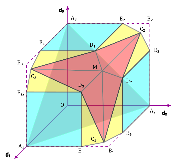
The coordinates of important vertices are listed below:
Remark: The vertices are achievable by using the scheme proposed in [4]. Vertices , , , and achieve DoF when , which is achieved by ZF beamforming approach with perfect current CSIT. Vertex achieves DoF when , which are achieved by the MAT scheme. In particular, vertex can be achieved by using Scheme , which consists of phases and totally time slots. Vertices are achieved by a one-time-slot scheme, Scheme . The achievability schemes will be discussed in detail as follows.
III-B Scheme (vertex )
III-B1 Phase
In the first phase of scheme , new symbol vectors for Rx-, Rx- and Rx- are prepared as , , , respectively, where
Each symbol contains bits of information, and . The symbol means where is a constant not scaled of . When transmitting the aforementioned symbol vectors, other accompanying symbols are sent, which are denoted as , , and , where . Each of the accompanying symbol contains bits of information and . The accompanying symbol is sent at time slot . For example, the symbol vectors sent in the first three time slots are given by
where denotes the normalized beamforming vector lying in the null space of and . At Rx-, the received signal in the first time slot can be expressed as
| (3) |
where . The desired accompanying symbol has power and the remaining two have power . Because is the overlapping of the three included symbols, Rx- can decode , which contains bits of information, at the rate of bits/s by considering remaining interference as noise. Afterwards, Rx- can remove from its received signal and decode their private symbol at the rate of bits/s as rest of the interference merges in noise. Using a similar method, in each time slot of Phase , Rx- is able to decode as well as their private symbols, i.e., . In order to accomplish the following phases, we repeat the first phase once for new symbol vectors where , and replace , and , respectively, as well as replace , respectively.
At the end of Phase , the BS has obtained perfect CSIT, with which it can perfectly reconstruct all the interference terms. Similar to the MAT scheme, the order- symbols will be reconstructed by using the reconstructed interference. Specifically, is digitalized and coded into , is digitized and coded into , as well as is digitized and coded into . Symmetrically, , and are also generated. Because each interference term is decoded at the rate of bits/s of information, according to the rate distortion theorem, each or also contains bits. In the rest of this section and are called order- common symbols.
III-B2 Phase
During this phase, the transmit signal vector, occurring at time slot is given by
| (4) |
where each order- common symbol and has power in order to satisfy the power constraint. For DoF analysis, since we only care about the power exponent of the received terms, we can safely remove the coefficient found in power of order-2 common symbols.
During these three time slots, each receiver will obtain a combination of and with power , a desired private symbols with power , and an interference part with power . For example, at time slot , Rx- will receive the following terms
| (8) | ||||
| (9) |
As the linear combination of and contains bits of information, it can be successfully decoded by regarding the rest of the terms as noise. Afterwards, the private symbol can be decoded at the rate of bits/s by using the successive decoding method. Similarly, at time slot , Rx- will be able to decode the combination of order- common symbols as well as their private symbols .
At the end of Phase , the BS has obtained perfect CSI. Similar to the MAT scheme, it will reconstruct the overheard interference and generate the order- common symbols, i.e., is coded from , is coded from , and is coded from . It is worth mentioning that as each combination of and is decoded at the rate of bits/s, each contains bits of information.
III-B3 Phase
In the two time slots of Phase , the BS will send two linear combinations of , and . Specifically, the symbol vector sent at time slot , where , is given by
| (10) |
where the constants , for are shared with the receivers.
The signal received by Rx- at time slot is given by
| (14) | ||||
where can be decoded at the rate of bits/s by regarding the rest of the terms as noise. Similar to Phase and Phase , the private symbol vectors can be decoded at the rate of bits/s by using the successive cancellation approach (SIC) approach.
III-B4 Backwards decoding and DoF calculation
The symbols contained in and can be decoded by Rx- by using the approach provided in the MAT scheme as all the required order- and order- common symbol vectors have already been obtained. Meanwhile, at Rx-, all the new private symbols included in and , where , can be decoded in each time slot by using the SIC method.
On one hand, this scheme sends , , , , , to receivers in time slots, which sums up to bits of information. Therefore, the total DoF gained for decoding , , , , , are . On the other hand, in each of the time slots, private symbol are sent for all the receivers and each of them contains bits of information. That is to say, the DoF per time slot for decoding is . Hence, the total DoF achieved by this scheme are
Given the symmetry of this scheme for Rx-, Rx-, and Rx-, each receiver obtains DoF.
III-C Scheme (vertices )
The Scheme describes the procedure to achieve Vertex in the DoF region. At this achievability scheme, occuring one time slot, the transmit symbol vector to be sent is
| (15) |
where is a private symbol for Rx- and . Symbols , , and are for Rx-, Rx-, and Rx-, respectively, and each of them has power . The received signal at Rx- can be expressed as
| (16) |
where denotes the channel entry from the first antenna at the BS to Rx-. Rx- will decode at rate bits/s by considering the rest of the terms as noise. Then, it can remove and decode symbol at the rate of bits/s because the other interference drowns into the noise level. Therefore, Rx- gets DoF in total.
On the other side, Rx- and Rx- will also be able to decode at rate bits/s. However, they regard it as an undesired symbol vector and remove it from the received signal. Afterwards, they can decode their private symbol at the rate of bits/s. Hence, each of them obtains DoF. As a result, the DoF vertex is achieved.
By changing into the corresponding symbols for Rx- or Rx-, the vertices and can be achieved, respectively.
III-D Extension to -user with -antenna BS scenario
For the proposed -user setting, two achievability schemes are considered, i.e., Scheme and Scheme . To be more specific, Scheme achieves the symmetric DoF vertex, i.e., all the users get the same DoF, while Scheme achieves the DoF vertex when one of the users gets one DoF similar to vertices in Figure 1.
III-D1 Scheme
Theorem 2
In a -user MISO BC, where the BS is equipped with antennas, each of the receivers is able to achieve
| (17) |
DoF per second per Hz.
Remark: This DoF region is consistent with two well known results. Specifically, when , the Scheme reduces to the MAT scheme, where DoF are achieved. When , the achievable DoF becomes one per user which can be simply achieved by using ZF beamforming method.
The MAT scheme is modified, in order to achieve this DoF vertex. Specifically, Scheme can be divided into two parts, the MAT part and the ZF part:
-
•
In the MAT part, the MAT scheme is performed but instead of constructing each symbol vector with bits of information, we construct it with bits of information. Consequently, each order- symbol vector used in the MAT scheme, where will contain bits of information. By using a backwards decoding approach as stated in [3], DoF are achieved.
-
•
In the ZF part, since all the symbol vectors in the MAT part contain bits of information, we can send them with power , and save the extra space to send new private symbol vectors at each time slot. Given that the BS is equipped with antennas, it can provide independent -dimensional vectors. Specifically, if is desired by Rx-, the symbol vector in the ZF part is beamformed as
(18) where denotes the beamforming vector in the null space of the estimated current channel vectors to all the receivers except Rx-. If , all the overheard interference will be at noise level. Therefore, at each time slot, there are symbols containing bits of information for each of the receiver and DoF are achieved.
As a result, the total DoF are
which are evenly allocated to the receivers.
III-D2 Scheme
Scheme is a straightforward extension of Scheme . Specifically, because the BS is equipped with antennas, it can provide linear independent -dimensional spaces. Let us denote the beamforming vector for the desired symbol vector for Rx- as , and define new symbols and intended for the same receiver. Then, the beamformed symbol vector can be written as
where and . For Rx-, , the received signals are
| (19) |
Rx- can first decode at rate bits/s by regarding the rest of the terms as noise. Then it can remove it from and decode its own private symbol at rate bits/s because the remaining interference is at noise level.
Taking into account that is intended for Rx-, the achieved DoF at Rx- are . At all the other receivers, the achieved DoF are .
IV Assymetric Case (, )
In this section, we present the achievable DoF region and achievability schemes for a -user MISO BC, where the BS is equipped with 2 antennas.
IV-A DoF Region
Theorem 3
The DoF region, achieved by the -user MISO BC with perfect delayed as well as imperfect current CSIT when the BS is equipped with antennas, can be formed by the following inequalities, i.e.,
All the important vertices are listed and the formed polygon is shown in Fig. 2. Specifically, the vertices are given by
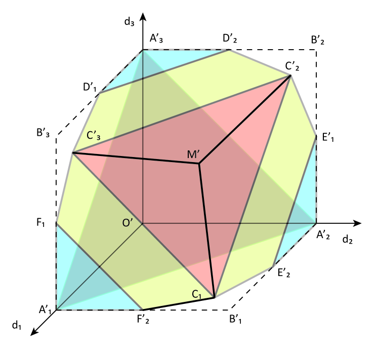
Remark: The DoF polygon represented by the triangle can be obtained by the scheme, where one DoF can be achieved totally. All the remaining vertices except Vertex achieve total DoF when . The total DoF achieved at vertex is , which is consistent to two well known results, i.e., when , DoF are achieved and when , DoF are obtained, as proved in [3].
IV-B Scheme for vertex
The total scheme is divided into three phases where the first two phases consist of time slots, while the last phase includes time slots. The two symbol vectors, sent to each of the receivers, are for Rx-, .
IV-B1 Phase
In the first phase, the BS sends signal vectors to two of the three receivers at each time slot, i.e., the symbol vector sent in the first time slot can be written as
which contains no symbol vector intended for Rx-. Symbol and denote the vectors in the span and the null space of , respectively. The power allocation of each of the symbol vectors are and . Symmetrically, the symbol vectors, sent in the following two time slots, are given by
At the receiver side, the received symbols and the corresponding power allocations in the first time slot are given by
where and describe the interference at Rx- and Rx-, respectively. Note that Rx- regards all its received signal as interference. The total power of the interference terms at Rx- is given by
| (20) |
by which we have . Similarly, has the same power. At the end of each time slot, the BS will obtain the perfect CSIT of this time slot, which enables it to reconstruct the interference terms, i.e., and . In order to make room for privates symbol that will be sent in later phases, each of the reconstructed interference will be digitalized into bits to make the digitalization error submerged in white noise. After the digitalization process, the digitalized version of is included in the new common symbol that will be sent in the next phase, where .
The symbols received in the other two time slots in this phase have similar form with the received signal as in the first time slot. In general, the BS reconstructs interference terms and each one will be digitalized into bits. Note that the other common symbols and , where , contain interference overheard by Rx-.
IV-B2 Phase
The second phase also consists of time slots and the symbol vectors sent at each time slot are symmetric. Specifically, in the -th time slot, the transmit symbol vectors are given by
| (21) |
where and are new private symbols for Rx- and Rx-, respectively, and .
Note that Rx-, , can decode at the rate of bits/s and remove it from its received signal. Then it can decode its desired symbol at bits/s. After obtaining perfect CSIT at the end of the -th time slot, the BS will generate new symbols by reconstructing interference terms observed by Rx- as and . Note that the symbol or is the digitalized symbol for the interference term containing and , respectively.
In the remaining two time slots, the BS will reconstruct the interference terms overheard at Rx-, Rx-, respectively. Consequently, digitalized symbols , , , and , representing the interference terms, are generated.
IV-B3 Phase
The symbol vector transmitted at the -th time slot, where , is given by
| (28) |
where are shared all receivers and the common symbol , where , contains two private symbol vectors similar to the second phase. To keep the scheme symmetric among all the receivers, private symbol vectors contained in are evenly transmitted to the three receivers. The most simple way to evenly allocate the symbols is to repeat the whole scheme three times and in each time, is destined to one receiver. By regarding the common symbol vector as noise, the receivers will be able to decode the sum of all the other terms at the rate of bits/s. After that, the private symbol can be decoded at the rate of bits/s.
IV-B4 Backwards decoding and DoF calculation
Similarly, the scheme can be divided into the MAT part and the ZF part. For the MAT part, the exact way to decode and , where refers to the MAT scheme. Note that each or contains two symbols with bits and bits each. Therefore, the achievable DoF per time slot in the MAT part are .
Meanwhile, for the ZF part, at each time slot, two new symbols are sent and each of them is decoded at the rate of bits/s. Altogether, during the last two phases, new private symbols are sent, each of which contains bits of information. Specifically in Phase , the . Thus, the total DoF achieved per time slots are .
Adding the DoF achieved in the MAT and the ZF parts, the total achievable DoF are
| (29) |
Note that the total DoF are symmetrically allocated to Rx-, Rx-, and Rx-.
V Conclusion
This paper proposed the DoF regions and achievability schemes in MISO time-correlated BC by taking into account for imperfect current as well as perfect delayed CSIT. In total, achievability schemes are provided for DoF regions, i.e., a -user and -antenna BS (symmetric) case as well as a -user and -antenna (asymmetric) case.
-
•
-User and -Antenna BS: How to achieve the DoF outer bound with -user and -antenna BS with imperfect current and perfect delayed CSIT was an open problem. We proposed the Scheme and achieved DoF, which is equal to the known published DoF outer bound. By varying , Scheme compromised between the MAT scheme and the ZF beamforming method . That is to say, the current CSIT is always beneficial. Moreover, we proposed the Scheme , which provided one receiver one DoF and all the other receivers DoF. Note that DoF can be achieved in total when .
-
•
-User and -Antenna BS: Firstly, a -dimensional DoF polygon consisting of surfaces was illustrated. Afterwards, Scheme was proposed, which achieved DoF in total, and therefore, the scheme is consistent with two well known results, i.e., when , a total of DoF are achieved as obtained by the MAT scheme, while when , DoF can be achieved as obtained by using the ZF method in case of only perfect current CSIT.
Acknowledgment
This research was supported by HIATUS and HARP projects, as well as a Marie Curie Intra European Fellowship within the 7th European Community Framework Programme for Research of the European Commission under grant agreements no. [265578], HIATUS and no. [318489], HARP, as well as no. [330806], IAWICOM.
References
- [1] V. Cadambe and S. Jafar, “Interference alignment and degrees of freedom of the K-user interference channel,” IEEE Trans. Inf. Theory, vol. 54, no. 8, pp. 3425–3441, 2008.
- [2] G. Caire, N. Jindal, M. Kobayashi, and N. Ravindran, “Multiuser MIMO achievable rates with downlink training and channelstate feedback,” IEEE Trans. Inf. Theory, vol. 56, no. 6, pp. 2845–2866, 2010.
- [3] M. Maddah-Ali and D. Tse, “Completely stale transmitter channel state information is still very useful,” IEEE Trans. Inf. Theory, vol. 58, no. 7, pp. 4418–4431, 2012.
- [4] S. Yang, M. Kobayashi, D. Gesbert, and X. Yi, “Degrees of freedom of time correlated MISO broadcast channel with delayed CSIT,” IEEE Trans. Inf. Theory, vol. 59, no. 1, pp. 315–328, 2013.
- [5] X. Yi, S. Yang, D. Gesbert, and M. Kobayashi, “The degrees of freedom region of temporally correlated mimo networks with delayed CSIT,” IEEE Trans. Inf. Theory, vol. 60, no. 1, pp. 494–514, Jan. 2014.
- [6] J. Chen and P. Elia, “Toward the performance versus feedback tradeoff for the two-user MISO broadcast channel,” IEEE Trans. Inf. Theory, vol. 59, no. 12, pp. 8336–8356, Dec. 2013.
- [7] P. De Kerret, X. Yi, and D. Gesbert, “On the degrees of freedom of the K-user time correlated broadcast channel with delayed CSIT,” in IEEE International Symposium on Information Theory Proceedings (ISIT), Jul. 2013, pp. 624–628.