Content-centric Routing in
Wi-Fi Direct Multi-group Networks
Abstract
The added value of Device-to-Device (D2D) communication amounts to an efficient content discovery mechanism that enables users to steer their requests toward the node most likely to satisfy them. In this paper, we address the implementation of content-centric routing in a D2D architecture for Android devices based on WiFi Direct, a protocol recently standardised by the Wi-Fi Alliance. After discussing the creation of multiple D2D groups, we introduce novel paradigms featuring intra- and inter-group bidirectional communication. We then present the primitives involved in content advertising and requesting among members of the multi-group network. Finally, we evaluate the performance of our architecture in a real testbed involving Android devices in different group configurations. We also compare the results against the ones achievable exploiting Bluetooth technologies.
I Introduction
It can be argued that the vast majority of wireless communicating devices in use today rely on an Access Point (AP)-based paradigm. Cellular networks, Wi-Fi hotspots, all require user devices to “associate” to a common base station before they can operate. Undeniably, such paradigm is convenient: it facilitates a uniform service provision, it simplifies management and it is essential in case billing is required. At the same time, it creates a cumbersome overhead for communications which, by virtue of the location of endpoints, might best be served by a direct link. Exploitation of Device-to-Device (D2D) connectivity, whether in an unrestrained or in a network-controlled fashion, is at the forefront of standardisation and research efforts. Such interest is spurred by the commercial appeal and widespread availability of Bluetooth Low Energy [1] and Wi-Fi Direct [2], technologies that smartphone and tablet manufactures are increasingly incorporating in their products.
While in the past D2D communication was largely relegated to cable-replacement use cases, today it is touted as a game-changing factor in mass communication, thanks to its enhanced spectral efficiency and traffic offloading capabilities. Some commonly envisioned scenarios for D2D are: machine-to-machine communication, Internet of Things architectures, infrastructure replacement (in case of failure), social content sharing. Additionally, D2D (and Wi-Fi Direct in particular) has the potentiality to play a crucial role in future LTE offloading strategies. LTE standardisation is looking at the interoperability with other D2D technologies by introducing the concept of network-assisted D2D communication: the cellular interface would jump-start the D2D link between suitable devices by handling the discovery and authentication phases, thus serving as broker party [3, 4, 5].
However, many of the promises in store for D2D communication lay bare what is arguably its biggest flaw: lacking a “static” infrastructure, the availability of content is, at best, spotty and unreliable. Even if requested content is cached by a nearby node, reachable through a multi-hop D2D path, a robust content discovery and retrieval mechanism is needed. Such mechanism should be aware, and, if possible, should leverage the peculiarities of the D2D environment: high node churn, volatile topologies and resource-constrained devices.
In this paper, we focus on the potentiality of Wi-Fi Direct as D2D communication technology in medium and large-scale scenarios, using open-source, non-rooted Android devices. Our contribution is manyfold.
-
•
For starters, we investigate in depth the limitations that the current Android OS exhibits in some crucial Wi-Fi direct features, and in the roles that devices can play in a D2D multi-device topology.
-
•
Secondly, we work around the above limitations by designing a multi-group, interconnected logical topology that overcomes the limitations of the physical one by exploiting transport-layer tunneling. Such logical topology allows us to enable bidirectional, inter-group data transfers, which would otherwise be impossible in today’s Wi-Fi Direct-based networks.
-
•
Thirdly, in order to address the content availability issue, we implement a content-centric routing architecture on our D2D topology. In content-centric routing, users do not need to know the physical whereabouts of data (as in traditional IP routing, in which the hosting device is pinpointed by a univocal identifier), but they just focus on the content they need and let the network do the rest. Routing tables thus carry content-oriented routing information that reflects both (i) the availability of specific content either in the local group of devices or in a nearby, reachable group, and (ii) the above transport-layer tunneling mechanism through which content can be reached.
-
•
At last, we implement a novel content registration/advertisement protocol that is designed to populate Content Routing Tables (CRT) consistently with the data that each user is willing to share (and thus advertises in the D2D network).
To our knowledge, our work is the first that tackles bidirectional, inter-group communication in Wi-Fi Direct networks, and proposes and implements a solution to support this data transfer paradigm. Furthermore, we realised a small-scale testbed using off-the-shelf Android devices to test both the feasibility of our multi-group topologies, as well as the efficiency of content-centric routing along with the registration/advertisement protocol.
The rest of the paper is organised as follows. Section II provides an overview of Wi-Fi Direct. Section III highlights some of the limitations that topology formation suffers from in WiF-Direct devices and details the multi-group communication mechanism. Our content-centric routing architecture and registration/advertisement protocol are presented in Section IV. Section V illustrates the results derived from our testbed implementation. Related work is discussed in Section VI, while Section VII draws some conclusions and points out directions for future research.
II The Wi-Fi Direct Technology
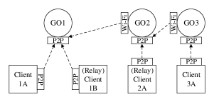
Wi-Fi Direct is a recent protocol standardized by the Wi-Fi Alliance [2], with the aim to enable D2D communications between nodes, referred to as peers. Communication among peers in Wi-Fi Direct occurs within a single group. One peer in the group acts as Group Owner (GO) and the other devices, called clients, associate to the GO (see, e.g., Fig. 1). Such roles within the group are not predefined, but are negotiated upon group formation. After the GO is elected, the role of each peer remains unchanged during the whole group session. Only when the GO leaves the group, the peers become disconnected and a new group must be created.
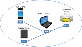
The group works as an infrastructure Wi-Fi BSS operating on a single channel, through which the peers communicate. The GO periodically transmits a beacon to advertise the group so as to enable other devices to discover and, possibly, join the group. As depicted in Fig. 1, each client is either a P2P client or a legacy client. A P2P client supports the Wi-Fi Direct protocol, whereas a legacy-client is a conventional Wi-Fi node that does not support Wi-Fi Direct and “sees” the GO as a traditional Wi-Fi AP. P2P clients and legacy clients coexist seamlessly in the same group.
It is important to note that Wi-Fi Direct has been designed to support D2D communication within a group, however its protocol does not prevent the communication between different groups. Indeed, a peer can act as a bridge between two groups, or between the group and other networks.
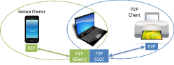
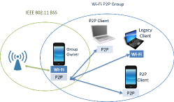
One possible scenario, as shown in Fig. 2, consists of a bridge peer (the middle node) behaving as GO for one group and as P2P-client in another group. We stress that the bridge peer must support two different MAC entities at layer 2, with two different MAC addresses. A peer can also act as a bridge between a Wi-Fi Direct group and a standard infrastructure BSS. This concurrent operation is shown in Fig. 3. Also in this case, the support for multiple MAC entities is required.
III Multi-group Communication with Android devices
As mentioned, we focus on user devices running an open-source Android OS due to their wide popularity, and we investigate how to provide bidirectional multi-group communication in networks composed of such devices.
Android devices offer a limited, controlled set of networking capabilities for security reasons. It is of course possible to “root” a device in order to access advanced capabilities, but we do not take this possibility into account since the rooting process requires skills that are beyond the average user, and it renders the warranty null and void. Thus, we only act upon application-layer functionalities, i.e., no changes can be performed at the transport or network layer (like changing IP addresses for P2P interfaces, configuring routing tables, etc).
A multi-group topology could be implemented by letting a device have two virtual P2P network interfaces: in this way, it could act as a bridge using a different MAC entity in each group. In non-rooted Android devices, however, the programmer cannot create a custom virtual network interface. Our experiments revealed that none of the following scenarios are feasible in Android, much though they are not expressly forbidden by the standard:
-
1.
a device plays the role of P2P client in one group and GO in another,
-
2.
a device behaves as the GO of two or more groups,
-
3.
a device behaves as client in two or more groups.
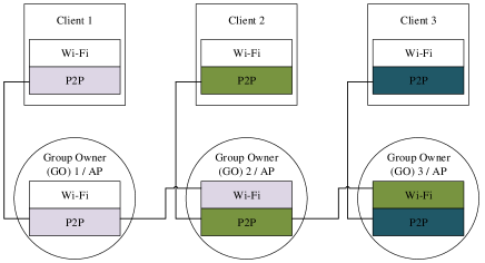
Thus, in order to create a multi-group physical topology (i.e., bridge nodes), we let a GO be a legacy client in another group. Specifically, we proceed as depicted in Fig. 4, where three inter-connected groups are formed with six devices. GOs are represented by circles and clients by squares. In each peer, we enable two network interfaces, one of which is the conventional Wi-Fi interface and the other (P2P) is used for Wi-Fi Direct connection. The interfaces used to form a group are highlighted using the same color, while connections are represented by lines. It is important to remark that each group represents a different Wi-Fi Basic Service Set (BSS). Furthermore, note that GO2 and GO3 also act as legacy clients of GO1 and GO2, respectively. GO1 is not acting as a legacy client since it is not associated to any other group. As discussed later in Section III-B, the fact that one GO is a legacy client of another GO affects its forwarding capabilities.
For ease of presentation, in the following we often take the three-group physical topology depicted in Fig. 4 as reference scenario and refer to the three groups as Group 1, Group 2 and Group 3, respectively.
III-A IP address assignment
In Android devices, once a Wi-Fi Direct connection is established, the GO automatically runs the DHCP to assign IP addresses to itself (192.168.49.1/24) as well as to the P2P clients or legacy clients in its own group (192.168.49./24 where is a random number to minimize the chance of address conflicts). Therefore, the P2P interfaces of all GOs have the same IP address, namely 192.168.49.1. The Wi-Fi interfaces of the GOs that act as legacy clients in another group are assigned an IP address in the format 192.168.49./24. Similarly, P2P interfaces of clients are assigned different IP addresses in the format 192.168.49./24.
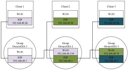
An example of IP assignment for the three-group topology is shown in Fig. 5, which highlights the address conflicts for the P2P interface of the GOs. Since GO1 is not associated with a Wi-Fi AP, no IP address is assigned to its Wi-Fi interface.
III-B Design of the logical topology
Given the above assignment of IP addresses, we show how to design a logical topology that implements multi-group communication. Our methodology overcomes the limitations of the physical topology and of its addressing plan, which prevent data transfers on some D2D links.
Let us start by discussing intra-group communication, as it is the basis for enabling bidirectional inter-group communication. Two cases have to be distinguished.
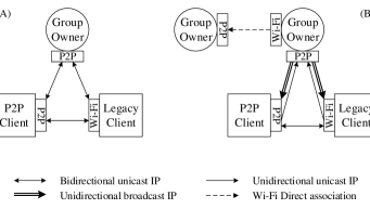
In the first case, depicted in Fig. 6(A), the GO is not connected to any other group as legacy client. Since Wi-Fi Direct has been designed to provide full connectivity among all nodes of an isolated group, all possible D2D communications are enabled. Thus, any pair of devices (GO, P2P clients and legacy clients) can exchange data at the IP layer. Note that, in the specific example in Fig. 5, Group 1 falls in this case (hence all D2D communications are allowed) since GO2 is a standard legacy client as far as GO1 is concerned.
In the second case, illustrated Fig. 6(B), the GO is also connected to another group as a legacy client. Referring again to the example network in Fig. 5, Group 2 and Group 3 fall in this case. All D2D unicast data transfers among clients (P2P or legacy clients) are allowed, thus TCP connections and/or UDP flows between clients are supported. Instead, between two GOs, or between a GO and its clients, only a subset of D2D data transfers are allowed. The reasons underlying this limitation are two. First of all, two neighboring GOs cannot communicate directly, because of the IP address conflict. Note that in this case one of the GOs acts as legacy client of the other GO, as in the example of Fig. 5 where GO2 is legacy client of GO1. When GO2 wishes to transmit an IP packet to GO1, the destination is set to 192.168.49.1 and the packet is thus sent to its local loop and not to the Wi-Fi interface. Also, when GO1 sends an IP packet to GO2 (192.168.49.134), GO2 discards it since its IP layer detects that the packet source address matches its own (192.168.49.1). The second reason pertains to the ordering of routing table entries in the GO, as implemented by the Android OS. When the GO wants to send a unicast IP packet to any client of its group, the packet is invariably sent through the GO Wi-Fi interface, since the latter entry is listed with higher priority than the P2P interface in the routing table of the device111We consistently observed this behavior for different devices, of different brand, running Android 4.3 and 4.4.. In the client-to-GO direction, instead, the communication is allowed since client routing tables list only one interface and no conflict occurs. In summary, bidirectional unicast data transfer between GO and its clients is not allowed, only unidirectional unicast communication between the client and the GO can take place. Hence, no TCP connection can be established between the GO and its clients, whereas UDP flows are allowed only from the clients towards their own GO.
Conversely, broadcast IP packets sent by the GO are always\footreffn:repeat sent through its P2P interface. This is an important observation as it allows the support of bidirectional data transfer between each client and its GO: broadcast IP packets can be used from the GO to the clients, while unicast IP packets can be adopted to transfer data from the clients to the GO. Note that broadcast packets generated by the GO will also reach the GOs associated to it as legacy clients, but then such packets will be discarded because of the conflict of source IP address, as discussed above. So, it is not possible for a GO to directly reach neighboring groups. Lines connecting the nodes in Fig. 6(B) summarize the possible intra-group data transfers at IP level.
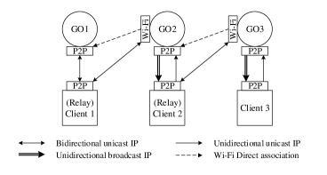
We can now focus on enabling inter-group communication in light of the issues discussed above. We recall that D2D communications are allowed between any two clients within the same group (i.e., not involving the GO at IP layer). Thus, also the communication between a P2P client and a legacy client that is also the GO of a different group is allowed in both directions. This observation is crucial, since it provides support for our novel design that exploits a client within the group as relay to reach a neighboring group. Specifically, we provide bidirectional, inter-group communication between neighboring groups by adopting the communication scheme shown in Fig. 7. To send data from the central group (Group 2) to its right side group (Group 3), we leverage a P2P client (Client 2) to relay the traffic toward GO3. Instead, to send data from Group 2 to its left side group (Group 1), GO2 itself is responsible to relay traffic toward a client in the left side group (Client 1).
In other words, we build a logical topology based on transport-level tunnels enabled by IP and MAC-layer connectivity, as follows.
-
•
Unidirectional UDP tunnels between a GO and its P2P clients (e.g., GO1 and Client 1). They are based on broadcast IP packets from the GO to clients and on unicast IP packets from clients to the GO. When reliable communication is required towards a single client, the GO can adopt a classical stop-and-wait protocol.
-
•
Bidirectional UDP or TCP tunnels between P2P clients and legacy clients within the same group (e.g., between Client 1 and GO2, or Client 2 and GO3).
Full connectivity among nodes in a multi-group network can thus be provided by leveraging a proper sequence of transport-layer tunnels established in the logical topology, and switching packets at the application layer (i.e., without rooting the devices).
III-C The role of the relay client
To define a routing process that properly leverages the above transport-layer tunnels, we select one client within each group, to act as a relay node with respect to neighboring groups. We name such node relay client. In the example in Fig. 5, Client 1 (Client 2) is the relay client connecting Group 1 (Group 2) to Group 2 (Group 3).
We implemented a basic election scheme at the application layer; more sophisticated solutions could be devised so as to design smart network topologies. According to our scheme, the GO sends a message to one of its clients, chosen at random among those that do not act as GO in another group, to elect it. To reach the desired client, the message is sent via a broadcast IP packet through the P2P interface. Indeed, if a unicast IP packet were used, it could be wrongly sent to the Wi-Fi interface (specifically, when the GO is also legacy client in another group). Note that the role of each client in the group, as well as in other groups, is known to its GO through application-layer signalling (see Sec. IV.B).
III-D The communication backbone
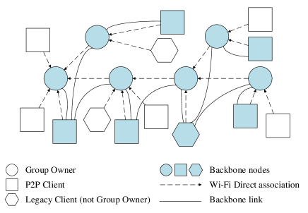
To disseminate data across a large set of devices, we then propose a logical tree topology, connecting all groups by extending the approach shown in Fig. 7 to an arbitrary number of groups.
By doing so, we build a communication backbone, as depicted in Fig. 8. The figure highlights in grey the GOs and the relay clients that compose the backbone and provide connectivity to all other clients (P2P and Wi-Fi clients that do not act as GOs, i.e., that are not involved in the traffic relay process). In principle, our approach might scale indefinitely, even if we were able to validate it experimentally only for few groups, as shown in Section V.
It is important to remark that a path over the backbone involving transfers from GO to relay Client within the same group requires a broadcast IP transmission for each of such transfers. Instead, transfers from relay client to GO do not require any broadcast IP transmission.


III-E A step-by-step example
For the sake of clarity, here we report a detailed description of the packet forwarding process in the scenario depicted in Fig. 9, when a packet flows from Client 1A to Client 3A, and viceversa, using UDP as transport layer. To help elaborate the procedure clearly, the message exchange at IP and MAC layers are shown in Figs. 10-13. Note that, since our focus is on content-centric routing, here we assume devices to be aware of the next-hop to contact in order to reach a content. The selection of the next-hop is determined by the sequence of transport-layer tunnels composing the network backbone. For instance, the path from Client 1A consists of the following hops: Client 1A Client 1B GO2 Client 2A GO3 Client 3A. The next section explains the acquisition of routing information by devices.
Below, we detail the steps that let a packet be delivered from Client 1A to Client 3A.
-
1.
Client 1A encapsulates the data in the payload of a unicast UDP packet and sends it directly to the relay Client 1B. This packet is sent at MAC layer to GO1, which behaves as an AP and re-sends it to the relay client.
-
2.
Client 1B processes the packet at the application layer and duplicates the payload into a new UDP packet, sent directly to the IP of the Wi-Fi interface of GO2. At MAC layer, the packet is sent to GO1, which re-sends it to the desired GO2 interface.
-
3.
GO2 processes the packet at the application layer and duplicates the payload into a new UDP packet. The UDP packet is sent as a broadcast IP packet through the P2P interface of GO2, thus reaching the relay client in Group 2.
-
4.
Client 2A processes the packet at the application layer and duplicates the payload into a new UDP packet, to be sent directly to the IP address of the Wi-Fi interface of GO3.
-
5.
Finally, GO3 processes the packet at the application layer and duplicates the payload into a new UDP packet, sent directly to destination Client 3A.
In case of a packet flowing from Client 3A to Client 1A, the following procedure takes place. For brevity, only IP layer packet transfers are highlighted.
-
1.
Client 3A encapsulates the data in the payload of a unicast UDP packet and sends it directly to GO3.
-
2.
GO3 (which is also a legacy client in Group 2) processes the packet at the application layer and duplicates the payload into a new unicast UDP packet, sent to the relay Client 2A.
-
3.
In its turn, Client 2A processes the packet at the application layer and creates a new UDP packet destined to the P2P interface of GO2.
-
4.
GO2 (which is also a legacy client in Group 1), again, creates a new UDP packet and sends it to the relay Client 1B.
-
5.
Finally, Client 1B forges a new UDP packet for the final destination, Client 1A.
Note that, in accordance with our discussion in Section III-D, the first example above implies two IP broadcast transmissions (i.e., transfers from a GO to a relay client within the same group), while the second example does not involve any broadcast IP packet.
IV Content-centric Routing
We propose a network architecture in which content delivery leverages the above forwarding scheme through a content-centric approach.
We assume that each node knows the neighboring node (next hop) to which it has to send the request for a specific content. How this knowledge is acquired is explained later in this section. When the request reaches the node with the desired content through a sequence of transport-layer tunnels, the content data is forwarded back to the requester, along the same path (i.e., sequence of tunnels) followed by the request packet. Note that this scheme is compatible with possible caching solutions adopted at intermediate nodes; however, for ease of presentation, we will assume that each content is provided by exactly one node in the network and that, when such node disconnects, the content becomes unavailable.
Two main data structures are responsible for content routing, as detailed below.
The Content Routing Table (CRT) provides the routing information to reach content items. For each item, identified by the MD5 hash of its name, the CRT stores the IP address of the next-hop node to reach the content provider, similarly to the “gateway” field of a traditional IP routing table. Note that the next-hop node definition must be tailored to the data forwarding scheme described in Section III.
Let us examine the possible next-hop values that can be associated to a specific content item. To this end, we consider two neighboring groups, and , and denote by RC() the relay client of group and by GO() the GO of ; a similar notation is used for devices in . Let us assume that the user requesting the content is in group . The CRT entry on the requesting user device will associate the following possible next-hop values to the requested item.
-
1.
The content item is available in . Then, the next hop is set as the IP address of the client in providing the content.
-
2.
The content item is available in , and is reachable through RC(). In other words, GO() is a bridge node (i.e., it is also a legacy client in ), and, according to our forwarding scheme, RC() can relay traffic to it. Thus, the next-hop for the requesting client, and for all group members with the exception of GO(), is RC(). The next-hop for RC() is the IP address associated with the Wi-Fi interface of GO(). In the example of Fig. 9, for a content available in Client 3A, the next-hop for Client 1A and GO1 is the relay client 1B; the next-hop for Client 1B is the Wi-Fi interface of GO2.
-
3.
The content item is available in , and is reachable through GO(), i.e., GO() is a bridge node as it acts as legacy client in . The next-hop for the requesting client, and for all members of , is the IP address of the P2P interface of GO(). The next-hop of GO() is the IP address of RC(). In the example of Fig. 9, for a content available at Client 1A, the next-hop for Client 3A is the P2P interface of GO3; the next-hop for GO3 is Client 2A.
If no match is found in the CRT of an intermediate node, the packet is discarded and a notification message is returned to the requester.
The information present in the CRT is updated only when new content becomes available, or a content item becomes unavailable, according to the protocol described in Section IV-A. Note that the proposed scheme can be easily extended with a weighted list of next-hops to support multiple copies of the same content, in case of cooperative caching mechanisms implemented in the network. Furthermore, standard methods to aggregate content routes in the CRT can be implemented to reduce the CRT size and propagate differential updates. Such methods are complementary to our scheme and out of the scope of this paper.
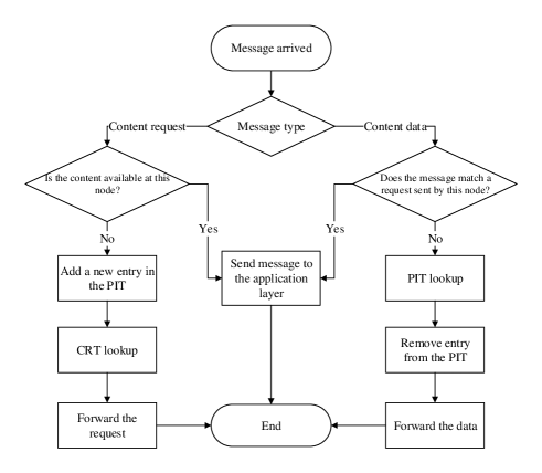
The second data structure is the Pending Interest Table (PIT), derived from CCN [6], which provides the information to route a content to the requester. Before an intermediate node forwards a content request, the node stores the IP address of the node interface from which the request was received. Devices thus record the “previous hop” for each requested content item and forward the content back to the requester upon receiving it; then, the corresponding entry is removed from the PIT. Note that, at a given device, there may be multiple pending requests for the same item. In this case, when the item reaches the device, the latter forwards it toward all requesting devices, duplicating it and sending it over the previous hops from which the corresponding requests were received. A timeout is set to remove pending requests for unavailable content. A content received by an intermediate node without any matching entry in the PIT is discarded.
The flow chart in Fig. 14 summarises the packet processing at an intermediate node of the communication backbone (relay client or GO), when a content data packet or a content request packet is received.
IV-A Content registration, advertisement and request
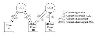
To build the CRT, we adopt a simple protocol based on the following two phases. Content registration is the initial phase in which a client advertises the availability of new content within the group. The message is sent from the client to the GO, which returns an acknowledgment (ACK), guaranteeing reliable registration of content. Content advertisement is the subsequent phase in which content is advertised internally and externally to the group. First, the GO sends a broadcast message to all (p2p and legacy) clients, to update their CRT and waits for an ACK from the relay client. Thanks to its broadcast nature, a single message is needed, regardless of the number of clients in the group. However, reliable reception is guaranteed only for the relay client. The broadcast message sent by the GO is discarded at the IP layer by the legacy clients that are GOs of other groups; thus, it will not propagate outside the group where it has been generated. In order to advertise the content to other groups, the relay client sends a content advertisement message to each legacy client that is also a GO of another group, and waits for the ACK. The example of Fig. 15 shows the sequence of application-layer packets that are exchanged when new content becomes available at Client 1A. After message ➇, all nodes in the two groups have updated their own CRT with the new content item.
Based on the above procedure, updated content information can be (surely) found only at the GOs and at the relay clients. Thus, upon generating a content request, a device that is neither a GO nor a relay client, first looks up the content information in its CRT. If no entry is available, it sends the request to its GO, which will process it as described in the previous section.
IV-B Message format
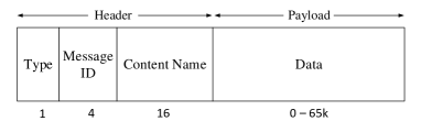
Our content-centric routing is based on one application-layer message, which may carry control information (e.g., content registration and advertisement), a content request, or the desired content item. The message is encapsulated in standard TCP or UDP segments, carried by IP packets. Fig. 16 reports the message format:
-
•
Type (1 byte) specifies the message type, among: Content registration (and ACK), Content advertisement (and ACK), Content data, Content request, Relay election (and ACK), notification of GO role in another group by a legacy client (and ACK).
-
•
Message identifier (4 bytes) is a random nonce that associates the ACK with the message it refers to.
-
•
Content name (16 bytes) is the MD5 hash of the content name. Note that any other hash function could be used to encode the name.
-
•
Data (0-65 kbytes) is the main payload, carrying control or content data.
V Experimental Evaluation
We set up a testbed including several Android devices of different type, namely, Google Nexus 7 and ASUS Transformer Pad TF300 tablets and 2 different smartphones (LG P700, Sony Xperia Miro ST23i). The Nexus tablets were equipped with Android 4.4.2 (API level 19), but our application was also tested with Android 4.3 (API level 18) on the same devices, before the operating system upgrade. LG smartphones used Android 4.0 (API level 14), which is the oldest version supporting Wi-Fi Direct. In our tests, LG smartphones acted as P2P clients and never as GOs, since the transport-layer tunnels from/to the GO discussed in Section III-B are fully enabled only for Android 4.3 and later versions. The ASUS tablets and the Sony Xperia were equipped with Android 4.2.1 (API level 17) and Android 4.0.4 (API level 14), respectively. Neither of them support Wi-Fi Direct; we used such devices only as legacy clients and not as group owners. This variety in the choice of devices allowed us to validate our multi-group communication mechanism in presence of heterogenous devices and different conditions. No device was rooted, to be sure that we could validate the approach for off-the-shelf devices.
We developed an Android application to implement our solution for bidirectional, multi-group communication and content-centric routing, as well as to validate the whole approach and assess its performance. In order to program the devices, we used the integrated development environment (IDE) Eclipse (version v22.0.1) with the ADT (Android Developer Tools) on Ubuntu 13.04. The ADT is officially provided by Google and allows users to build, test, and debug applications on Android.
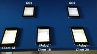
For brevity and ease of presentation, in the following we show the results that we obtained using the experimental setup depicted in Fig. 17, i.e., two Wi-Fi Direct groups. Group 1 includes 4 devices (GO1, Client 1A, Client 1B and GO2, the latter acting as legacy client in Group 1), while Group 2 comprises 2 devices (GO2 and Client 2A). Client 1B and Client 2A operate as relay clients in their own groups. This setup is equivalent to the scenario discussed in the example of Fig. 15.
All the tablets were located in proximity of each other, to reduce the effects of propagation delays and signal attenuation due to distance. All experiments have been carried out in the laboratory, during evening hours to reduce interference from active neighboring APs. We manually chose channel 11 for Wi-Fi and Wi-Fi Direct communications, since, according to a preliminary monitoring of the spectrum, it appeared to be the least interfered channel. The interference power we measured on channel 11 was always between -91 dBm and -98 dBm (i.e., quite low) during all the experiments. As a term of comparison, the most crowded channels showed levels of interference between -65 dBm and -83 dBm.
After the Wi-Fi Direct groups were set up, we tested the content-oriented routing scheme in two phases. In the initial phase we investigated the performance only of the content delivery scheme (i.e., of the forwarding mechanism through transport-layer tunnels), while in the second phase we tested the content registration and advertisement mechanism.
V-A Content delivery performance
Here, we focus on the performance that can be achieved for the content data transfer, from one device to another, based on the data delivery scheme explained in Section III. We manually configured the CRT and PIT tables to avoid any protocol overhead due to content requests and table updating. Each content is divided into chunks of fixed size equal to 1400 bytes, to avoid IP fragmentation. To vary the offered traffic load, the content provider periodically sends a new chunk, encapsulated into a Content Data message, with the chunk rate being a varying application parameter.
We validated the data delivery mechanism by picking different pairs of devices among the possible ones, and letting them act as source-destination nodes. We therefore verified the full bidirectional connectivity over the whole multi-group network, and recorded the application-layer throughput and the packet losses experienced at the IP layer, as functions of the application-layer traffic offered load. For each configuration, we run 100 different experiments, to obtain throughput results with a 1% relative width of the 95% confidence interval.
In the following, we mainly focus on the scenarios detailed below, always run on the testbed shown in Fig. 17:
-
1.
“2 devices - 1 group” (2d1g), in which the source is Client 1A and the destination is GO1. The communication between a client and its GO involves just one hop at IP and MAC layer, since each message is sent through a single unicast IP packet, carried by a single MAC frame.
-
2.
“3 devices - 1 group” (3d1g), in which the source is Client 1A and the destination is Client 1B. The communication between two clients in the same group involves one hop at the IP layer, but two hops at the MAC layer (Client 1A GO1 Client 1B).
-
3.
“4 devices - 2 groups” (4d2g), in which the source is Client 2A and the destination is Client 1B. The communication between the two clients in 2 groups requires two hops at IP layer (Client 2A GO2 Client1B) and three hops at MAC layer (Client 2A GO2 GO1 Client 1B).
-
4.
“2 devices - 1 group - broadcast” (2d1g-B), in which the source is GO2 and the destination is Client 2A. The communication within the same group now occurs in the opposite direction with respect to the 2d1g case, but notably the single-hop communication is based on a broadcast transmission, since GO2 is also legacy client of GO1.
-
5.
“4 devices - 2 groups - broadcast” (4d2g-B), in which the source is Client 1B and the destination is Client 2A. The communication between the two clients in two different groups involves 2 hops at IP layer (Client 1B GO2 Client 2A) and 3 hops at MAC layer (Client 1B GO1 GO2 Client 2A) in which the last hop is based on a broadcast transmission.
Note that we do not show the case of content transfer from GO1 to Client 1A since it is equivalent to the 2d1g case; indeed, GO1 is not a legacy client of any other group, thus it can send unicast IP packets directly to Client 1A.
For fair comparison, we start by evaluating the first three cases, which imply only unicast transmissions; then, we will move on to the last two cases, involving broadcast transmissions.


Fig. 18 shows the application-layer throughput vs. the offered load. As expected, the throughput increases with the load, and reaches a maximum value of about 19 Mbit/s (2d1g scenario), 8.4 Mbit/s (3d1g scenario) and 5.0 Mbit/s (4d2g). These results are coherent with the fact that the throughput decreases proportionally to the number of hops, due to the channel contention among the transmitters operating on different hops. Note that current available Wi-Fi Direct interfaces work only on a single frequency channel and, thus, the whole multi-group network is part of the same collision domain. In general, the number of hops traversed by a packet depends only on the distance, in terms of number of groups, over the backbone between source and destination (usually, we have two hops at the MAC layer per each traversed group), whereas it is independent of the total number of devices composing the network. While the single collision domain increasingly affects the performance as the number of active transmitters grows, having the hop number independent of the group size improves scalability. Additionally, the impact of the single collision domain lessens as the network gets larger: when transmitters are far away from each other, some degree of spatial diversity is possible and interference among parallel transmissions greatly reduces. It follows that the network throughput decreases less than proportionally to the number of hops.
Fig. 19 shows the overall packet loss probability. Note that packet losses are almost negligible in the 2d1g scenario. They become noticeable for the 3d1g case ( for the lowest load) but still have little impact on the throughput. Under the 4d2g scenario, instead, packet losses are more significant ( for the lowest load), since the transmissions over the three hops that every message has to undergo at the MAC layer interfere with each other.
Figs. 20 and 21 depict throughput and packet losses, respectively, for the last two scenarios, 2d1g-B and 4d2g-B, both implying one broadcast transmission by GO2. The maximum throughput is 4.6 Mbit/s for 2d1d-B and 2.5 Mbit/s for 4d2g-B. Such numbers are much smaller than in the first three scenarios, since, at MAC layer, 802.11 broadcast packets are transmitted at the minimum data rate (6 Mbit/s), whereas much higher rates are used for unicast transmissions (up to 54 Mbit/s). Note also that, even if three hops are involved in 4d2g-B, the first two hops occur through unicast transmissions (hence at much higher data rate than broadcast transmissions) and, thus, they mildly affect the throughput. Looking at Fig. 21, it can be seen that the loss probability is higher in the two scenarios with broadcast transmissions than in previous cases. This behavior is also expected: in case of failure, broadcast packets are never retransmitted at the MAC layer, thus the reliability of the communication from the GO to its relay client is severely reduced.
In summary, the performance of the communication backbone is strongly affected by the traffic flow direction. The two different relay schemes, adopted within a group to work around the constraints imposed by Wi-Fi Direct, show significantly different performance. The main bottleneck is represented by broadcast communications from the GOs to their relay clients.
V-B Content registration and advertisement performance
We now investigate the performance of the process for content registration and advertisement, by programming one device to periodically register a new content item and measuring the latency experienced at each node to update its own CRT.
We focus on the scenario in Fig. 15 where, every second, Client 1A registers one new content item with GO1, through the two messages ➀, ➁ reported in the figure. The experiment lasted 1 minute, with a total of 60 new registered items. The sequence of the advertisement messages that are generated and transmitted is represented by messages ➂-➇; all of them are processed at the application layer. Table I reports the latency measured at each hop, as well as the end-to-end latency in the 4d2g scenario, obtained by logging the time at which each device processes the incoming advertisement message. Such message triggers a CRT update and the transmission of the corresponding ACK. Clock offsets affecting the logs of different devices were computed through a packet-level trace obtained by an external laptop sniffing traffic in monitor mode.
| Transfer | Incoming | Average | 95% confidence |
|---|---|---|---|
| message | [ms] | interval [ms] | |
| GO1 Client 1B | ➂ | 250 | 206-294 |
| Client 1B GO2 | ➄ | 304 | 219-390 |
| GO2 Client 2A | ➆ | 226 | 199-252 |
| GO1 Client 2A | ➂ | 780 | 688-872 |
The overall latency required to update the farthest node is less than one second. According to our data, the main contribution is due to the processing time at the application layer of each node since the transmission time of the advertisement messages (and their ACKs) is negligible. This points to the need for optimized versions of relay code running at backbone nodes.
V-C Comparison with Bluetooth
The Android devices we used in the previous experimentation are equipped with Bluetooth 3.0, which also supports multi-hop communications. For this reason, we have chosen to compare the performance of multi-group communications in Wi-Fi Direct and in Bluetooth under similar scenarios.
Under the same testbed setup shown in Fig. 17, we run a logical topology in Bluetooth, shown in Fig. 22, to mimic exactly the Wi-Fi Direct multi-group topology, considered in the previous sections. We set up two piconets, P1 and P2. P1 consists of three devices: one master (M1) and two associated slaves (S1A, S1B). P2 consists of two devices: one Master (M2) and one associated Slave (S2A). To enable bridging capabilities among the two piconets, M2 is also connected to M1 as a slave. We developed a single Android application (not requiring to root the devices) that can generate traffic, relay packets between the two piconets and record performance metrics. We run this application on each device, manually configuring the role of each device (source/destination/gateway).
We focused mainly on the maximum achievable throughput in different scenarios, when changing the source-destination pairs. We adopted 990 bytes as the application-layer packet size, to avoid packet fragmentation. The throughput is always measured at the receiver’s application layer.

To faithfully mimic the scenarios considered in Sec. V-A, we define each piconet as a “group” and consider the following cases:
-
1.
“2 devices - 1 group” (2d1g), in which the source is S1A and the destination is M1. The packets are directly sent from S1A to M1 at the MAC layer without any relay.
-
2.
“3 devices - 1 group” (3d1g), in which the source is S1A and the destination is S1B. The traffic generated by S1A is first sent to the M1, i.e. the piconet master. Each packet is processed by M1 at application layer and then relayed to S1B. The overall communication involves two hops at both application and MAC layer (S1A M1 S1B).
-
3.
“4 devices - 2 groups” (4d2g), in which the source is S2A and the destination is S1B. The traffic traverses P1 and P2 thanks to the two application-layer relays operated by the two masters, M2 and M1. The overall communication involves 3 hops both at application and MAC layer (S2A M2 M1 S1B).
Note that the Bluetooth does not support broadcast, hence we do not consider the last two scenarios in Sec. V-A involving broadcast communications.
We now compare the maximum throughput between Wi-Fi Direct and Bluetooth. Table II provides the maximum throughput achieved in each scenario, measured at application layer. The throughput is expressed in terms of absolute value and normalized value, as described below.
For Bluetooth, the maximum absolute throughput with 2 devices in direct communication (2d1g) is around 1.9 Mbit/s, which is consistent with the maximum net data rate of 2.1 Mbit/s. For 2-hop communications (3d1g), the throughput decreases by a factor of two (0.9 Mbit/s); this is expected, since the communication slots used by master M1 are divided in two: one to receive the data from one slave (S1A) and one to send the data to the other slave (S1B). In the case of two piconets (4d2g), the maximum throughput is slightly less than 3d1g, since simultaneous transmissions (S1AM1 and M2S2A) can occur in the two different piconets.
Table II reports also the throughput achievable by Wi-Fi Direct, which is much higher with respect to Bluetooth in absolute terms, thanks to the higher data rates.
| Throughput Mbit/s | Normalized throughput | |||||
| Technology | 2d1g | 3d1g | 4d2g | 2d1g | 3d1g | 4d2g |
| 1 hop | 2 hops | 3 hops | 1 hop | 2 hops | 3 hops | |
| Bluetooth | 1.92 | 0.94 | 0.77 | 64% | 31% | 26% |
| Wi-Fi Direct | 22.9 | 10.6 | 6.2 | 35% | 16% | 9.5% |
For a fair comparison, we also report the normalized throughput obtained by dividing the throughput by the actual physical data rate adopted during the communication. In Wi-Fi Direct the rate must adapt to the channel conditions, and in this case we observed, most of the times, packets sent at the maximum data rate (65 Mbit/s) thanks to the small physical distance (always less than 40 cm) between the devices. For Bluetooth, the physical data rate adopted for the normalization is 3 Mbit/s, which is the data rate for Bluetooth 3.0 operating in the devices.
By considering only the normalized throughput in Table II, Wi-Fi Direct achieves about 35%, 16% and 9.5% of the maximum throughput, respectively for increasing number of transmission hops, while Bluetooth achieves about 64%, 31% and 26% of it. The lower efficiency of Wi-Fi Direct is due to the contention-based protocol that regulates the access to the same radio channel. As already observed, the throughput decreases proportionally to the number of transmission hops. Instead, in Bluetooth the efficiency is larger thanks to the slotted time version of the protocol, whose access is coordinated by the Master.
VI Related Work
Several recent studies have investigated the features and the performance of the Wi-Fi Direct technology.
One of the first studies has appeared in [7], where Camps Mur et al. consider a single-group Wi-Fi Direct network with the group owner sharing access to a 3G network with a set of connected devices. The work analyzes the power saving protocols defined in Wi-Fi Direct and design two algorithms that use such protocols to save energy while providing good throughput performance. An improved power management scheme for Wi-Fi Direct is proposed in [8], which dynamically adapts the duty cycle of P2P devices to the properties of the application to be supported.
An overview and experimental evaluation of Wi-Fi Direct using two laptops running Linux is presented in [9], where the emphasis is on the standard group formation procedures and the performance that they exhibit in terms of delay and power consumption. Group formation is also the focus of the work in [10], which investigates the ability to create opportunistic networks of devices using Wi-Fi Direct to establish communication links. The performance of group formation is studied experimentally, by varying the protocol parameters and considering scenarios that are typical of opportunistic networks. A preliminary study of multi-group physical topologies of Wi-Fi Direct networks can be found in our previous work [11], where however only some of the limitations of the Android OS are investigated and only unidirectional D2D communication is tackled.
The use of Wi-Fi Direct as a D2D technology to be integrated into LTE and LTE-A cellular networks is explored in [4, 5, 12]. In particular, while [4] mainly focuses on architectural issues, [5] and [12] also quantify the estimated network performance gains from offloading cellular traffic onto Wi-Fi Direct-based, D2D connections.
As for content dissemination and sharing in mobile ad hoc networks, a number of solutions have been proposed in the literature, e.g., [13, 14, 15]. However, very few works exist that specifically address Wi-Fi Direct-based networks. Among these, the study in [16] presents a Wi-Fi Direct-based overlay architecture for content sharing among peers belonging to the same group. In particular, they leverage the P2PSIP protocol, which enables real-time communication using the application-layer signaling protocol SIP in a peer-to-peer fashion. The work in [17], instead, implements the decentralized iTrust mechanism [18] for information publication and retrieval. In particular, it proposes a peer management technique to facilitate group creation and allow peers to set up and maintain connectivity over Wi-Fi Direct.
As mentioned, to the best of our knowledge, none of the existing works has investigated, solved and experimentally evaluated bidirectional communication in Wi-Fi Direct multi-group networks.
VII Conclusions and Future Work
We implemented bidirectional, multi-group communication in Android devices supporting the recent Wi-Fi Direct protocol. This allowed us to extend the achievable communication range for a protocol whose current implementation in off-the-shelf, unrooted Android devices has been tailored just to single group D2D communication.
In particular, we proposed a solution to overcome the limitations of the physical Wi-Fi Direct network topology and of its addressing plan, and we built a logical topology that enables bidirectional inter-group data transfers. The logical topology we devised is based on a cooperative traffic relaying scheme among adjacent groups and, through transport-layer tunnels, leads to the formation of a network backbone that provides full network connectivity. We also devised a content-centric routing scheme, which properly exploits the above backbone and allows content advertisement, discovery and retrieval in arbitrary D2D network topologies. We implemented our solution in Android and validated it by developing a testbed comprising a heterogenous set of devices.
Our work opens up several future research directions. Firstly, an in-depth study could be carried out to determine the system scalability with the number of network devices. Such study could also factor in the choice of nodes to be elected as relay clients (their number and typology) as well as the techniques to efficiently manage the consequences of node churning. Secondly, our data transfer mechanism can support distributed strategies for the formation of smart topologies involving multiple groups and covering extended geographical areas. Lastly, bidirectional, inter-group communication can be the basis for disruptive cooperative applications and service models.
VIII Acknowledgements
This work was partially supported by Telecom Italia S.p.A. under the “Smart Connectivity” Research Contract.
References
- [1] “Bluetooth low energy,” http://www.bluetooth.com/Pages/low-energy-tech-info.aspx, 2014.
- [2] “Wi-Fi Direct Alliance,” http://www.wi-fi.org/, 2014.
- [3] G. RP-122009, “Study on LTE device to device proximity services,” 3GPP TSG RAN Meeting #58, 2012.
- [4] A. Asadi and V. Mancuso, “WiFi Direct and LTE D2D in action,” in IFIP Wireless Days (WD), Valencia, Spain, 2013, pp. 1–8.
- [5] S. Andreev, A. Pyattaev, K. Johnsson, O. Galinina, and Y. Koucheryavy, “Cellular traffic offloading onto network-assisted device-to-device connections,” IEEE Communications Magazine, vol. 52, no. 4, pp. 20–31, 2014.
- [6] B. Ahlgren, C. Dannewitz, C. Imbrenda, D. Kutscher, and B. Ohlman, “A survey of information-centric networking,” IEEE Communications Magazine, vol. 50, no. 7, pp. 26–36, 2012.
- [7] D. Camps-Mur, X. Perez-Costa, and S. Sallent-Ribes, “Designing energy efficient access points with wi-fi direct,” Computer Networks, vol. 55, no. 13, pp. 2838–2855, 2011.
- [8] K.-W. Lim, W.-S. Jung, H. Kim, J. Han, and Y.-B. Ko, “Enhanced power management for Wi-Fi Direct,” in Wireless Communications and Networking Conference (WCNC), 2013, pp. 123–128.
- [9] D. Camps-Mur, A. Garcia-Saavedra, and P. Serrano, “Device-to-device communications with Wi-Fi Direct: overview and experimentation,” IEEE Wireless Communications, vol. 20, no. 3, pp. 96–104, 2013.
- [10] M. Conti, F. Delmastro, G. Minutiello, and R. Paris, “Experimenting opportunistic networks with WiFi Direct,” in IFIP Wireless Days (WD), Valencia, Spain, 2013, pp. 1–6.
- [11] Y. Duan, C. Borgiattino, C. Casetti, C. Chiasserini, P. Giaccone, M. Ricca, F. Malabocchia, and M. Turolla, “Wi-Fi Direct multi-group data dissemination for public safety,” in World Telecommunications Congress (WTC), Berlin, Germany, June 2014.
- [12] A. Pyattaev, K. Johnsson, A. Surak, R. Florea, S. Andreev, and Y. Koucheryavy, “Network-assisted D2D communications: Implementing a technology prototype for cellular traffic offloading,” in IEEE Wireless Communications and Networking Conference (WCNC), Istanbul, Turkey, April 2014.
- [13] M. Fiore, C. Casetti, and C. Chiasserini, “Information density estimation for content retrieval in MANETs,” IEEE Transactions on Mobile Computing, vol. 8, no. 3, pp. 289–303, 2009.
- [14] P. Meroni, E. Pagani, G. Rossi, and L. Valerio, “An opportunistic platform for android-based mobile devices,” in Proceedings of the Second International Workshop on Mobile Opportunistic Networking, ser. MobiOpp. ACM, 2010, pp. 191–193.
- [15] P. Tiago, N. Kotilainen, and M. Vapa, “Mobile search - social network search using mobile devices demonstration,” in IEEE Consumer Communications and Networking Conference (CCNC), January 2008, pp. 1245–1245.
- [16] T. Duong, N.-T. Dinh, and Y. Kim, “Content sharing using P2PSIP protocol in Wi-Fi Direct networks,” in International Conference on Communications and Electronics (ICCE), 2012, pp. 114–118.
- [17] I. Lombera, L. Moser, P. Melliar-Smith, and Y.-T. Chuang, “Peer management for iTrust over Wi-Fi Direct,” in International Symposium on Wireless Personal Multimedia Communications (WPMC), 2013, pp. 1–5.
- [18] I. Lombera, L. Moser, P. Melliar-Smith, and Y. Chuang, “Mobile decentralized search and retrieval using SMS and HTTP,” Mobile Networks and Applications, vol. 18, no. 1, pp. 22–41, March 2013.