An experimental test of the viscous anisotropy hypothesis for partially molten rocks
Abstract
Chemical differentiation of rocky planets occurs by melt segregation away from the region of melting. The mechanics of this process, however, are complex and incompletely understood. In partially molten rocks undergoing shear deformation, melt pockets between grains align coherently in the stress field[1, 2]; it has been hypothesized that this anisotropy in microstructure creates an anisotropy in the viscosity of the aggregate[3]. With the inclusion of anisotropic viscosity, continuum, two-phase-flow models reproduce the emergence and angle of melt-enriched bands that form in laboratory experiments[4, 5]. In the same theoretical context, these models also predict sample-scale melt migration due to a gradient in shear stress. Under torsional deformation, melt is expected to segregate radially inward[5, 6]. Here we present new torsional deformation experiments on partially molten rocks that test this prediction. Microstructural analyses of the distribution of melt and solid reveal a radial gradient in melt fraction, with more melt toward the centre of the cylinder. The extent of this radial melt segregation grows with progressive strain, consistent with theory. The agreement between theoretical prediction and experimental observation provides a validation of this theory, which is critical to understanding the large-scale geodynamic and geochemical evolution of Earth.
Department of Earth Sciences, University of Minnesota, Minneapolis, Minnesota 55455, USA.
Department of Earth Sciences, University of Oxford, Oxford OX1 3AN, UK.
Earthquake Research Institute, University of Tokyo, Tokyo 113-0032, Japan
Shear deformation of partially molten rocks gives rise to melt segregation into sheets (bands in cross-section) that emerge at a low angle to the shear plane. This mode of segregation was predicted with two-phase flow theory[7] and subsequently discovered in experiments[8, 9]. It has been proposed that melt-enriched bands, if present in the mantle of Earth, would permit rapid extraction of melt[10], produce significant anisotropy in seismic wave propagation[11], and provide a mechanism for the seismic discontinuity that is, in some places, associated with the lithosphere–asthenosphere boundary[12]. The emergence[13] and low angle[14] of melt-enriched bands under simple-shear deformation can be reproduced using two-phase flow theory with a non-Newtonian, isotropic viscosity. This theory describes the flow of a low-viscosity liquid (melt) through a permeable and viscously deformable solid matrix (grains)[15]. However, an unrealistically strong stress-dependence of viscosity was required to match the low angle of bands observed in experiments[14]. This disagreement between models and experiments found a possible resolution by the incorporation of anisotropic viscosity arising from coherent alignment of melt pockets between grains (i.e., melt-preferred orientation, MPO) in response to a deviatoric stress[3, 16, 17, 5].
Crucially, with the inclusion of viscous anisotropy, two-phase flow theory also predicts a simultaneous but distinct mode of melt segregation driven by large-scale gradients in shear stress. This mode is termed base-state melt segregation[4, 5, 6]. Base-state melt segregation is not predicted if viscosity is isotropic; thus, its occurrence in experiments represents a test of the hypothesis that MPO leads to anisotropy in viscosity. Below we explain base-state melt segregation in more detail; we then present new experimental results that demonstrate its occurrence.
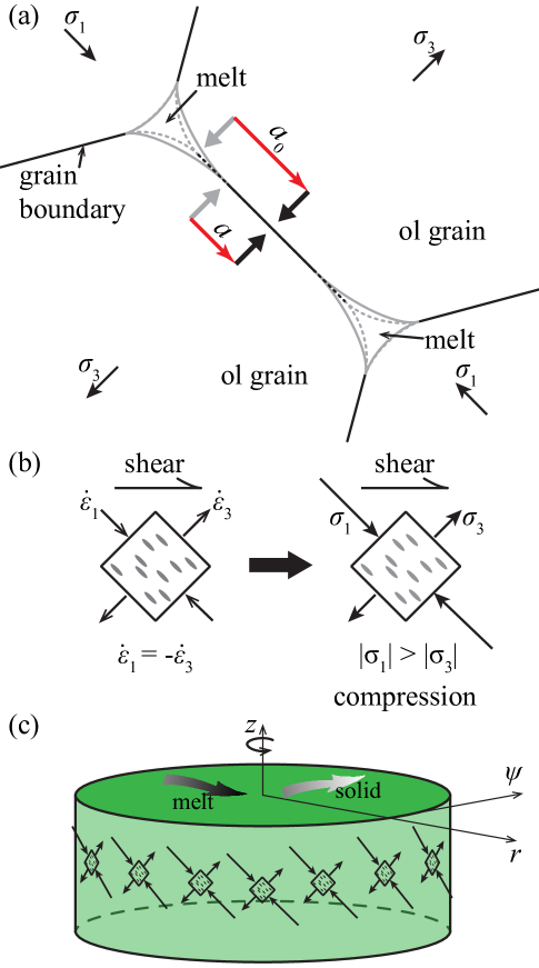
Figure 1a illustrates how anisotropy in grain/melt microstructure (i.e., MPO) produces viscous anisotropy through the mechanics of diffusion creep[3]. For a representative grain in an aggregate subjected to a deviatoric stress, the contact area with neighbouring grains decreases for grain boundaries that are normal to the direction of the minimum principal stress (the minimum eigenvalue of the deviatoric stress tensor; compression positive). A decrease in contact area shortens the diffusion pathway for material transport along this boundary relative to grain boundaries with different orientations. Since melt provides a fast pathway for diffusion, this change in the contiguity between neighbouring grains reduces the timescale of the diffusive response to the component of stress. Conversely, an increase in grain–grain contact area in the direction of the maximum principal stress lengthens the diffusion pathway on this surface and thus the timescale for diffusive response to stress in this direction.
To translate these concepts from the microscopic to the continuum scale, consider a representative element of volume (REV) that is large enough to contain many microscopic units (grains and melt pockets) and small enough to define a point property at the scale of macroscopic features of interest (Fig. 1b). Under deviatoric stress, melt pockets in the REV coherently align normal to the direction and the timescale for the diffusive response to stress is reduced in this direction. If the dominant deformation mechanism of the aggregate is diffusion creep, this rapid response imparts a reduction of the continuum viscosity in the direction[18, 3]. Likewise, the change in grain contiguity associated with increases the viscosity in that direction.
Viscous anisotropy can be quantified with a highly symmetric, fourth-rank tensor (Supp. Mat.). The orientation of this tensor is described by three angles that rotate it with respect to the system coordinates. This rotation is used to align anisotropy with the principal directions of deviatoric stress. As a simplifying approximation, we assume that, at each point in the domain, the plane containing and is parallel to the imposed shear direction and perpendicular to the imposed shear plane. This leaves only one angle to be determined, the angle between the shear plane and the direction. The magnitude of anisotropy is parameterised with two scalars: specifies the viscosity reduction in the direction; specifies the viscosity increase in the direction. When either or both and are non-zero at a point in the continuum, the viscosity at that point is anisotropic. The associated tensor then has non-zero off-diagonal terms that couple shear stress to normal strain rate (and vice versa). It is these terms that give rise to base-state segregation[4, 5].
To clarify the physical mechanism of base-state segregation, consider a cylindrical sample in a sealed chamber, deformed in torsion at a constant twist rate (Fig. 1c). Before any deviatoric stress is applied, the grain/melt microstructure is isotropic and the rate of (de)compaction is zero everywhere within the sample. With initiation of twisting, as a consequence of the deviatoric stress, a MPO develops and the viscosity becomes anisotropic. The imposed strain rate, aligned melt pockets, and consequent pattern of stress are shown schematically in Figure 1b–c. The disparity between and gives rise to a net compression that, because it is everywhere tangent to the cylinder, is a compressive hoop stress. This compressive hoop stress pushes the solid grains radially outward and causes a pressure gradient that drives melt radially inward[5] (details provided in Supp. Mat.). This differential motion is the base-state melt segregation under torsional deformation.
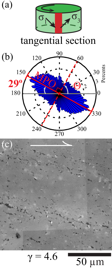
To test this prediction and hence the hypothesis that viscosity is anisotropic, we imposed a constant twist-rate on cylindrical samples of partially molten rock that initially had uniform melt fraction (Table 1). In tangential sections of quenched samples that were deformed in torsion (Fig. 2), we observe aligned melt pockets and low angle, melt-enriched bands. Melt-enriched bands are also evident in transverse sections (Fig. 3). More importantly, analyses of optical micrographs of transverse sections reveal a gradient in melt fraction in the radial direction, with melt concentrated toward the axis of the cylinder. This gradient in melt fraction corresponds to the base-state melt segregation predicted if viscosity is anisotropic. Our observations of MPO, melt-enriched bands, and radial melt segregation are detailed in subsequent paragraphs.
The rose diagram in Figure 2b demonstrates that at a local shear strain of , melt pockets are aligned at 29∘ to the shear plane, antithetic to shear direction. In contrast, the expected direction, based on cylindrical simple shear flow with isotropic viscosity, is 45∘ to the shear plane. The observed low angle of melt alignment means that, at this shear strain, either melt pockets are not normal to the direction[2] or has rotated counter-clockwise. The reason for this alignment is unknown; it might be due to the emergence of chains of melt pockets[19] (Fig. 2c) or to the anisotropic viscosity itself. In the theory of two-phase flow with viscous anisotropy, elaborated in the Supplementary Material, it is generally assumed that melt pockets align perpendicular to , as suggested by deformation experiments on an analogue material at small strains ()[20]. The observed MPO, therefore, may represent a subtle but important discrepancy between observation and theory that we return to below. Despite this possible discrepancy, the observed, strong MPO demonstrates the microstructural anisotropy that hypothetically causes viscous anisotropy.
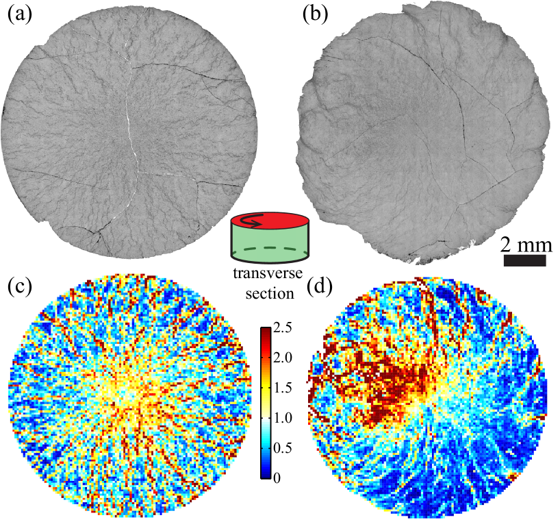
Two-phase flow theory with anisotropic viscosity[5] also predicts the emergence of sheets of high melt fraction that appear as bands in two-dimensional sections[9]. In Figure 3, these features appear as radial lines of high melt fraction where sheets cross the transverse section. For the sample deformed to an outer-radius shear strain of (Fig. 3a, c), the melt-enriched bands are distributed uniformly around the cylinder, whereas at a larger strain of (Fig. 3b, d), the azimuthal distribution of melt-enriched bands is inhomogeneous, dominated by several extraordinarily large bands. Because the total strain decreases toward the centre of the cylinder, the region close to axial centre exhibits less banding. More significantly, however, Figures 3c and d demonstrate a general increase in melt fraction toward the centre of the cylinder, consistent with the predicted base-state migration of melt radially inward.
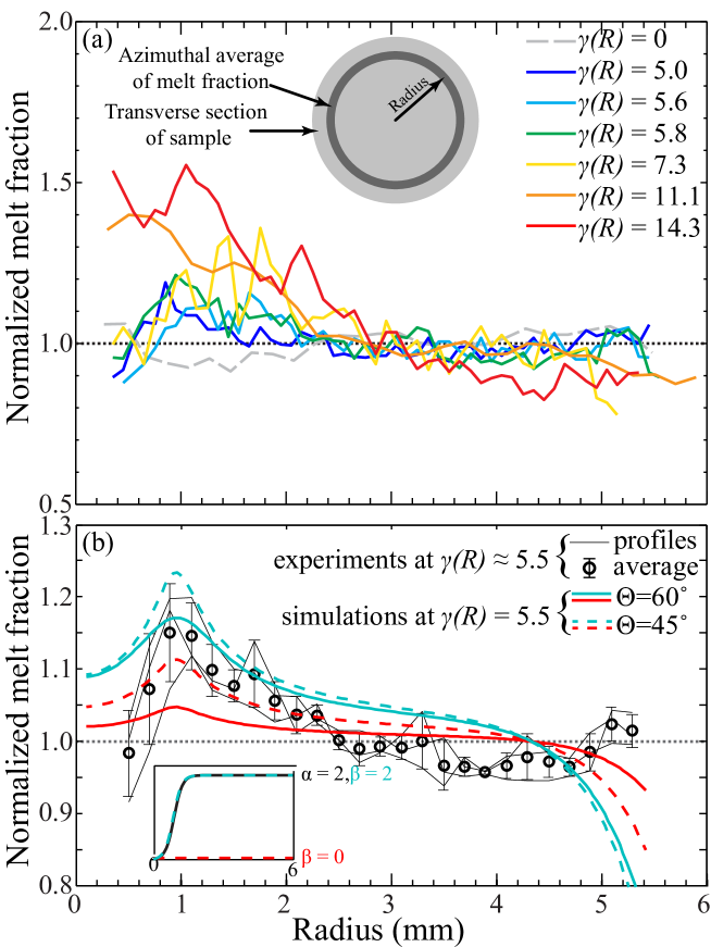
Radial profiles of the azimuthally averaged, normalized melt fraction are presented in Figure 4a for seven experiments, each with a different final strain. The melt fraction in an experiment with no deformation (grey line) varies by less than 10% along a radius. In all deformed samples, the melt fraction increases toward the centre of the cylinder — evidence for base-state segregation. For the three samples deformed to an outer-radius shear strain of , each radial profile of melt concentration reaches its peak at a radius of mm, corresponding to a shear strain of . Melt fraction decreases from that point toward the axis of the cylinder; this behavior is expected because the low-stress/low-strain region at small radius has little or no MPO and hence has essentially isotropic viscosity (). For samples deformed to higher outer-radius shear strains ( and ), peaks in melt fraction occur at a radius of mm. The sample with the highest outer-radius shear strain () exhibits the largest ratio of maximum to minimum melt fraction (Table 1), a measure of the strength of base-state melt segregation. Except for the samples sheared to outer-radius shear strains of and , the maximum in melt fraction increases with increasing shear strain. In summary, the results presented in Figure 4a demonstrate that, with increasing strain, the pressure gradient induced by anisotropic viscosity drives melt inward, increasing the maximum value of the azimuthally averaged melt fraction and decreasing the radius at which this maximum occurs.
Figure 4b compares the azimuthally averaged profiles of normalized melt fraction from three samples deformed to with those derived from numerical simulations. The data points in 4b, which are the mean values of the of the azimuthal averages at each radius, reach a maximum normalized melt fraction of 1.15 at mm and a minimum of 0.95 at mm. For comparison, radial profiles of melt fraction from numerical simulations of samples deformed to at an initial compaction length of and a bulk-to-shear viscosity ratio of . In the simulations, two conditions are used for the angle of viscous anisotropy: (1) 45∘, suggested by previous experiments[20], and (2) 60∘, suggested by Figure 2. The other variable in the simulations is the magnitude of viscous anisotropy. In all four simulations, increases from zero at the centre of the cylinder to at mm and then remains constant at larger radii. In two of the simulations, mimics the behavior of . In the other two simulations, is zero at all radii. In the decompaction region (i.e. at small radii), profiles with 45∘ exhibit higher melt fractions than those with 60∘, while profiles with exhibit higher melt fractions than those with and . The profile with 60∘ and is in the most consistent with the experimental results. However, some clear differences exist between the simulated and the experimental profiles. First, for mm the simulated profiles lie above experimentally measured profile. Second, the abrupt decrease in the simulated profiles at mm was not observed experimentally. Despite these quantitative discrepancies, all simulated porosity profiles are in good qualitative agreement with those from experiments, in terms of both the amplitude and the radial position of the porosity maximum.
In this paper we presented experimental observations of the radial distribution of melt in partially molten rocks deformed in torsion to large strain. For this deformation geometry, the theory of melt segregation with anisotropic viscosity predict a radial distribution of melt fraction. The inclusion of viscous anisotropy in the theory is a necessary and sufficient condition for the development of radially inward, base-state melt segregation. Our experiments test this prediction, and the results reported here are in general agreement with theory, validating the viscous-anisotropy hypothesis. This experimental validation of MPO-induced viscous anisotropy represents a significant advance in our understanding of the relationship between microstructure and continuum mechanics of partially molten rocks, and it also exposes details of the linkage between deformation, MPO and viscosity that are not captured by present models. In Earth, partially melting largely occurs in regions of active deformation — places where melt-preferred orientation will occur. Inclusion of viscous anisotropy in models of the dynamics of the partial molten mantle will likely predict shear-induced melt migration that profoundly influences melt segregation, mantle dynamics, and chemical evolution of our planet.
Samples were fabricated from mixtures of fine-grained powders of olivine from San Carlos, AZ, plus 10 vol.% alkali basalt from Hawaii[21]. Olivine powders were obtained by grinding San Carlos olivine crystals in a fluid-energy mill to produce a particle size of 2 m. Before mechanically mixing with alkali basalt powders with a particle size of 10 m, the olivine powders were dried at 1373 K for 12 h at an oxygen partial pressure near the Ni-NiO buffer to remove water and carbon-based impurities introduced during the grinding process. Mixtures were uniaxially cold-pressed at 100 MPa into nickel capsules and then hydrostatically hot-pressed at 1473 K and 300 MPa for 3.5 h in a gas-medium apparatus[22]. After hot-pressing, samples were cut into thin cylinders with a diameter of mm and a thickness of 3 to 5 mm. The cut sample was then placed into a nickel capsule with spacers cored from a coarse-grained natural dunite as end caps, thus providing non-reactive, impermeable boundaries during deformation[23]. The sample, Al2O3 spacers and pistons, and ZrO2 pistons were enclosed in an iron jacket for deformation.
Torsion experiments were conducted at a shear strain rate of 10-3.5 s-1, a temperature of 1473 K, and a confining pressure of 300 MPa in a gas-medium apparatus fitted with a torsion actuator[22]. After achieving the target strain, each sample was cooled rapidly (2 K/s) to 1300 K under the torque imposed at the end of the deformation experiment to preserve the deformation-produced microstructure and then cooled to room temperature with no torque applied. After deformation, with the iron jacket and the nickel capsule dissolved in acid, the deformed sample was cut in half perpendicular to torsional axis, leaving two transverse sections for examinations. Each transverse section was polished on a series of diamond lapping films down to 0.5 m, followed by a final step using colloidal silica. The section was then examined by reflected-light optical microscopy after chemically etching with diluted HF to highlight melt pockets.
To map the whole transverse section with an area of 113 mm2, a mosaic image consisting of 2209 high-resolution (0.3 m per pixel) optical micrographs was used. A binary image with melt appearing white was created from this mosaic image using using a combined image segmentation method, which includes edge detection[24, 25, 26] and a threshold of grayscale. Then a profile of melt fraction was calculated from the area fraction of the white pixels.
References
- [1] Kohlstedt, D. L. & Zimmerman, M. E. Rheology of partially molten mantle rocks. Annual Review of Earth and Planetary Sciences 24, 41–62 (1996).
- [2] Zimmerman, M. E., Zhang, S., Kohlstedt, D. L. & Karato, S.-i. Melt distribution in mantle rocks deformed in shear. Geophysical Research Letters 26, 1505–1508 (1999).
- [3] Takei, Y. & Holtzman, B. Viscous constitutive relations of solid-liquid composites in terms of grain boundary contiguity: 1. Grain boundary diffusion control model. Journal of Geophysical Research 114, B06205 (2009).
- [4] Takei, Y. & Holtzman, B. Viscous constitutive relations of solid-liquid composites in terms of grain boundary contiguity: 3. Causes and consequences of viscous anisotropy. Journal of Geophysical Research 114, B06207 (2009).
- [5] Takei, Y. & Katz, R. F. Consequences of viscous anisotropy in a deforming, two-phase aggregate. part 1. governing equations and linearized analysis. J. Fluid Mech 734, 424–455 (2013).
- [6] Katz, R. F. & Takei, Y. Consequences of viscous anisotropy in a deforming, two-phase aggregate. part 2. numerical solutions of the full equations. J. Fluid Mech 734, 456–485 (2013).
- [7] Stevenson, D. Spontaneous small-scale melt segregation in partial melts undergoing deformation. Geophysical Research Letters 16, 1067–1070 (1989).
- [8] Holtzman, B., Groebner, N., Zimmerman, M., Ginsberg, S. & Kohlstedt, D. Stress-driven melt segregation in partially molten rocks. Geochemistry Geophysics Geosystems 4, 8607 (2003).
- [9] King, D., Zimmerman, M. & Kohlstedt, D. Stress-driven melt segregation in partially molten olivine-rich rocks deformed in torsion. Journal of Petrology 51, 21 (2010).
- [10] Kohlstedt, D. & Holtzman, B. Shearing melt out of the earth: An experimentalist’s perspective on the influence of deformation on melt extraction. Annual Review of Earth and Planetary Sciences 37, 561 (2009).
- [11] Kendall, J.-M. Teleseismic arrivals at a mid-ocean ridge: Effects of mantle melt and anisotropy. Geophysical Research Letters 21, 301–304 (1994).
- [12] Kawakatsu, H. et al. Seismic evidence for sharp lithosphere-asthenosphere boundaries of oceanic plates. Science 324, 499 (2009).
- [13] Spiegelman, M. Linear analysis of melt band formation by simple shear. Geochemistry, Geophysics, Geosystems 4 (2003).
- [14] Katz, R. F., Spiegelman, M. & Holtzman, B. The dynamics of melt and shear localization in partially molten aggregates. Nature 442, 676–679 (2006).
- [15] McKenzie, D. The generation and compaction of partially molten rock. Journal of Petrology 25, 713 (1984).
- [16] Takei, Y. & Holtzman, B. Viscous constitutive relations of solid-liquid composites in terms of grain boundary contiguity: 2. Compositional model for small melt fractions. Journal of Geophysical Research 114, B06206 (2009).
- [17] Butler, S. Numerical models of shear-induced melt band formation with anisotropic matrix viscosity. Physics of the Earth and Planetary Interiors 200, 28–36 (2012).
- [18] Cooper, R. F. & Kohlstedt, D. L. Rheology and structure of olivine-basalt partial melts. Journal of Geophysical Research 91, 9315–9323 (1986).
- [19] Holtzman, B. & Kohlstedt, D. Stress-driven melt segregation and strain partitioning in partially molten rocks: Effects of stress and strain. Journal of Petrology (2007).
- [20] Takei, Y. Stress-induced anisotropy of partially molten rock analogue deformed under quasi-static loading test. Journal of Geophysical Research: Solid Earth (1978–2012) 115 (2010).
- [21] Morgan, Z. & Liang, Y. An experimental and numerical study of the kinetics of harzburgite reactive dissolution with applications to dunite dike formation. Earth and Planetary Science Letters 214, 59–74 (2003).
- [22] Paterson, M. & Olgaard, D. Rock deformation tests to large shear strains in torsion. Journal of Structural Geology 22, 1341–1358 (2000).
- [23] Qi, C., Zhao, Y.-H. & Kohlstedt, D. L. An experimental study of pressure shadows in partially molten rocks. Earth and Planetary Science Letters 382, 77–84 (2013).
- [24] Canny, J. A computational approach to edge detection. Pattern Analysis and Machine Intelligence, IEEE Transactions on PAMI-8, 679–698 (1986).
- [25] Lim, J. Two-dimensional signal and image processing. Englewood Cliffs, NJ, Prentice Hall, 1990, 710 p. 1 (1990).
- [26] Parker, J. Algorithms for image processing and computer vision (Wiley Publishing, 2010).
The authors are thankful to Mark Zimmerman and Matěj Peč for helps with experiments and analyses, and to Yan Liang and Clint Conrad for providing the alkali basalt. This study is supported by NSF grant EAR-1214876. Katz is grateful to the Leverhulme Trust for support. Numerical models were run on ARCHER, the UK national supercomputer.
The authors declare that they have no competing financial interests.
Correspondence and requests for materials should be addressed to C. Qi (email: qixxx063@umn.edu).
| Sample | (s-1) | (MPa) | ||
|---|---|---|---|---|
| PI0767 | 11.1 | 2.2910-4 | 187 | 1.6 |
| PI0811 | 5.6 | 1.8410-4 | 237 | 1.2 |
| PI0812 | 5.8 | 1.8410-4 | 163 | 1.4 |
| PI0817 | 5.0 | 2.3510-4 | 197 | 1.3 |
| PI0839 | 7.3 | 1.8410-4 | 237 | 1.7 |
| PI0891 | 14.3 | 2.0410-4 | 179 | 2.0 |
Online Supplementary Material
The viscosity tensor
The diffusion-creep viscosity tensor of a partially molten rock can be calculated by using a microstructure-based model[3]. The grain coordinates are defined independently of the continuum coordinates . Each grain in the aggregate is assumed to have 14 circular contacts with equal radius. Microstructural anisotropy is represented by a decrease (or increase) in the radius of the two contact faces in the (or ) direction. By substituting this contact geometry into equation (42) of Takei & Holtzman[3], is calculated as
| (1) |
where and correspond to the shear and bulk viscosity of an isotropic matrix, and (or ) represents the decrease (or increase) in viscosity in the (or ) direction.
For illustration, we consider a two dimensional problem in which contiguity is increased in the direction and decreased in the direction (in other words, MPO is aligned according to the instantaneous directions of principal stress). Furthermore, we assume that the – plane is parallel to the – plane. Let be the angle between the and axes. Then, by a coordinate transformation[5] of expression (1), the viscosity tensor in the continuum coordinates is
| (2) |
where only 21 of the 81 components are shown; the others are readily obtained from the symmetry of . The factor in front of the matrix represents the shear viscosity that decreases exponentially with increasing melt fraction . represents at reference melt fraction , and is the porosity weakening factor. The parameter represents the bulk-to-shear viscosity ratio. Parameters and represent the magnitude of viscous anisotropy in the reduced and increased directions, respectively. Parameters , , and are assumed to be independent of melt fraction based on the theoretical result[3, 5].
When and , (1) and (2) are equal to those used in previous studies[5, 6]. The present formulation is more general than that one because it allows for the effect of contiguity change in the direction as well as the direction. In obtaining solutions to the governing equations, is usually taken such that the axis is in the direction, as discussed above. However, because is defined by the direction of microstructural anisotropy independently of the resultant stress, it can be used to describe a general MPO direction (Fig. 2).
Base-state segregation in torsion
The anomalous character of the base-state melt segregation in torsion bears some elaboration. Takei & Katz[5] showed that viscous anisotropy has a general tendency to cause melt segregation up a gradient in shear stress, and demonstrated the occurrence of base-state melt segregation directly driven by a gradient of shear stress. In torsion, shear stress increases with increasing radius. However, the inward melt flow is driven by the negative hoop stress, which is opposite in direction to general tendency. A detailed explanation for this anomalous result for torsion deformation is presented in Takei & Katz ([5], Section 5.2). Irrespective of these subtleties, viscous anisotropy plays an essential role in the generation of the negative hoop stress that drives base-state segregation (Fig. 1). The occurrence of radially inward melt segregation in torsion can therefore be appropriately used to test the viscous anisotropy hypothesis.