Demonstration of relativistic electron beam focusing by a laser-plasma lens
Abstract
Laser-plasma technology promises a drastic reduction of the size of high energy electron accelerators. It could make free electron lasers available to a broad scientific community, and push further the limits of electron accelerators for high energy physics. Furthermore the unique femtosecond nature of the source makes it a promising tool for the study of ultra-fast phenomena. However, applications are hindered by the lack of suitable lens to transport this kind of high-current electron beams, mainly due to their divergence. Here we show that this issue can be solved by using a laser-plasma lens, in which the field gradients are five order of magnitude larger than in conventional optics. We demonstrate a reduction of the divergence by nearly a factor of three, which should allow for an efficient coupling of the beam with a conventional beam transport line.
Laboratoire d’Optique Appliquée, ENSTA - CNRS UMR7639 - École Polytechnique, 828 Boulevard des Mar chaux , 91762 Palaiseau, France
Centro de Laseres Pulsados, Parque Cient fico, 37185 Villamayor, Salamanca, Spain
Electron beams from laser-plasma accelerators[1, 2, 3] have typical normalized transverse emittances of about or below 1 mm.mrad[4, 5, 6, 7], comparable or even smaller than those of linear accelerators delivering similar energies[8, 9]. Yet, this small emittance is mostly due to a sub-micrometer source size[10], while the beams typically have rather large divergence of a few milliradians. Their energy spread, of a couple of percents[11], is also at least one order of magnitude larger than in linear accelerators. This raises several issues for the beam transport and hence for key applications of laser-plasma accelerators such as free electron lasers and high energy colliders[12, 13, 14, 15]. In particular, the transverse emittance tends to increase during a free drift, because electrons with different energies rotate with different velocities in the transverse phase space[16]. The emittance increase is tolerable[17] if the drift length . Here is the initial normalized emittance, the mean Lorentz factor, the root-mean-square (RMS) relative energy spread and the RMS divergence. Regarding state of the art laser-plasma accelerators[11, 7, 18, 5], the above condition indicates that the drift length should be smaller than 1 to 5 cm, depending on the exact conditions. In other words, electrons must be focused within a few centimeters from the accelerator exit in order to be transported efficiently.
Focusing the beam within such a short distance requires very high transverse field gradients. Quadrupole magnets which are generally used to transport electron beams, operate at gradients of T m-1, which is two orders of magnitude less than required. Though using non-adjustable permanent magnet configurations with millimeter size aperture, field gradients of up to 500 T m-1 have been reported[19], further enhancement is limited due to manufacturing issues, demagnetization effects, etc. An electron beam transport line based on quadrupole-technology will therefore degrade the quality of a laser-plasma electron beam, rendering it useless for most applications. As they can sustain much higher gradients, plasmas could help to drastically miniaturize focusing optics, similar to the miniaturization achieved by laser plasma accelerators, and hence to avoid any emittance growth. Incidentally, the idea to use plasma to focus an electron beam[20] is almost as old as the idea to use plasma to accelerate electrons[21]. It was proposed to focus an electron beam using the radial fields created in the wake of the electron beam itself, when it propagates in a plasma. The so-called plasma lens was demonstrated in the context of conventional accelerators[22, 23, 24, 25], but it has not been considered for focusing electron beams from laser plasma accelerators, due to the ultra-short length of these beams. Indeed, there is always a finite length at the bunch head over which the focusing is very non-uniform[26, 27]; for ultrashort bunches from laser-plasma accelerators this length is comparable the bunch length[28]. The laser-plasma lens was recently proposed, and validated by 3-dimensional particle-in-cell simulations, to solve this issue[29, 30]. In the following, we present an experimental demonstration of this concept.
In a laser plasma accelerator, the wakefields in which electrons are accelerated, present both longitudinal components, which are responsible for the energy gain[31], and transverse components, which make electrons oscillate and lead to betatron radiation[32]. The idea of the laser-plasma lens is to use these transverse fields to focus the electron beam. Its principle is illustrated in Fig. 1a. A laser pulse drives a wakefield in a first gas jet, diffracts in free space, and drives again a wakefield in a second jet. As a result, an electron beam is generated and accelerated in the first jet; it then drifts in the free space, where the interaction with the plasma is negligible, and is focused by the transverse components of the wakefield in the second jet. In general, transverse oscillations in a laser-wakefield cannot be used to focus an electron beam, because the beam electrons oscillate out of phase (there is no correlation between the electron position and its propagation angle). In a laser-plasma lens, the required synchronization is operated by the free drift. During the drift, the trajectory of individual electrons is , with and being the transverse position and propagation angle at the accelerator end, and the longitudinal distance from the accelerator end. Hence, for , is almost proportional to : the position is strongly correlated to the propagation angle. Because of this correlation, electrons oscillate almost in phase in the second laser-wakefield (the laser-plasma-lens), except for a small detuning arising from the beam energy spread (which impacts the oscillation frequency) and from the dependance of on . Thus, the plasma can act as a lens whose strength depends on its length and density. More specifically, the electron beam will be collimated if the focusing fields vanish when the transverse momentum is minimum for most electrons.
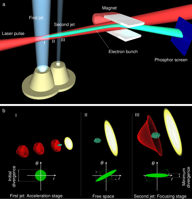
The principle of the laser-plasma lens is further illustrated by the phase-space traces in Fig. 1b. The free drift creates a correlation between and , then the phase-space trace rotates in the second gas jet, leading to a decrease of the beam divergence. The trace area gives the transverse emittance, which is conserved during the focusing process. This emittance conservation can be used to estimate the minimum divergence , where and are the normalized emittance and the RMS divergence at the accelerator end, and is the distance between the two gas jets. We see that the drift length is a key parameter to enhance the collimation. Note that this is a rough estimate, which assumes that the transverse fields in the lens are perfectly linear and neglects both the increase of the beam size during the phase space rotation and chromatic effects, i.e. influence of the beam energy spread; a more accurate analysis shows similar trends[29]. Note also that a noticeable electron density is tolerable in the drift space as long as the transverse forces do no prevent the electron beam to diverge. While decreases as increases, longer drift lengths do not necessarily imply smaller divergences. As the laser diffracts while propagating in free space, the laser intensity and thus the wakefield amplitude in the second jet decrease with increasing , resulting in only a partial collimation of the electrons for long . This puts an upper limit on the drift length, meaning that there is always a trade-off between low and efficient wakefield generation (necessary to get an actual divergence reduction).
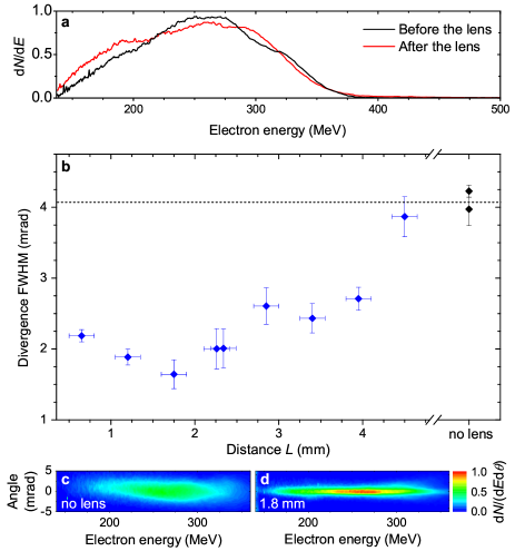
The laser-plasma lens, in the collimation configuration, was demonstrated at LOA using the Salle Jaune laser system (see Methods, for information on the laser system, the gas targetry and divergence measurements). At the end of the accelerator stage, electrons had a mean energy of MeV (RMS error) and a beam divergence of mrad. The electron beam had a few pC charge and was stable shot-to-shot, suggesting that electrons are injected into the accelerator by longitudinal self-injection[33]. The laser plasma lens does not modify significantly the charge, the mean energy nor the spectrum shape (see Fig. 2a). In contrast, Fig. 2b shows that the beam divergence can strongly decrease in the lens, down to mrad. The final divergence depends on the distance from the accelerator to the lens. It decreases as increases for mm and increases with for mm. The evolution of the divergence is governed by two effects, the decrease of the minimum achievable divergence , and the decrease of the laser intensity, which reduces the strength of the focusing fields for long . Indeed, the Rayleigh length at the accelerator exit is below 400 m (see Methods). After 1.8 mm of propagation the laser beam diameter and intensity are thus m FWHM and Wcm-2. Therefore, the wakefield in the lens is in the linear regime and the strength of the focusing fields strongly depends on the laser beam size and intensity. More precisely, the gradient of the focusing fields in the lens evolves as[29] . As a result, these fields can be too strong for short , leading to excessive focusing, and too low for long , leading to insufficient focusing. In Fig. 2, the transverse force seems to vanish for mm, while the lowest divergence is obtained for mm. Note that for the shortest lengths the wakefield may be in the non-linear regime.
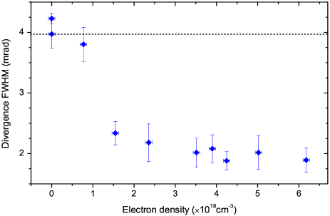
In addition to the drift length, the electron density and the length of the second jet can also impact the lens properties. The influence of the electron density is illustrated in Fig. 3. According to the model from Ref. [29] the focusing force varies as , where is the plasma wave vector, the RMS length of the laser pulse and the distance between the laser and the considered electron. The term in brackets corresponds to the amplitude of the transverse wakefield; it is maximum when the laser pulse is resonant with the plasma wave, i.e. for . The strength of the lens depends also on the position of the electron beam in the wakefield. This effect is described by the sine term; electrons experience the largest focusing force when , and are defocused for . The combination of both terms leads to a complex influence of the electron density on the focusing strength. For low densities ( cm-3 in Fig. 3), the focusing fields are very weak and the divergence is hardly reduced. As density increases the transverse focusing fields rise, which leads to the desired beam collimation. In Fig. 3, the lowest divergence is obtained for cm-3. The fact that the divergence remains almost constant for higher densities suggests that the focusing force has a local maximum, in the range cm-3, around cm-3. For even higher densities (not investigated in the experiment), the divergence should increase and eventually exceed the initial divergence when the fields become defocusing (for ). Note that, for long , the mean density which is effectively experienced by the electron beam during the focusing process may be significantly smaller than the peak density indicated in Fig. 3, because the focusing process is likely to occur only in the rising edge of the second gas jet (the focusing force decreases as ).
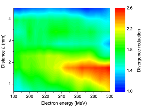
Up to this point, the electron beam was implicitly assumed to be mono-energetic, and in Figs. 2b and 3 only the divergence at 270 MeV was considered. Yet, a careful analysis of the angularly-resolved electron spectra in Fig. 2c-d reveals that electrons of different energies are not focused to the same extend. This is shown more clearly in Fig. 4, which displays the reduction factor of the beam divergence as a function of both the electron energy and the distance between the two stages. A couple of observations can be made from this plot. First, the reduction factor is larger towards higher energies. This is likely due to the decrease of at higher energies, both because varies as , and because in this particular experiment, the divergence at the accelerator end increases with . Second, the optimal length decreases as the electron energy increases. This is because the amplitude of the transverse fields required to focus the beam increases with the electron energy. Lengthening tends to lessen the focusing fields and hence enhances the focusing of low energy electrons (similar results can be obtained by decreasing the electron density). Nonetheless, Figs. 2b-c and 4 show that an electron beam with an energy spread exceeding MeV can be strongly focused, as a whole, using a laser-plasma lens.
We demonstrated the collimation of an electron beam by a laser-plasma lens. The electron beam was accelerated in a laser-plasma accelerator up to MeV, before going through a laser-plasma lens. At the lens exit, the beam divergence was reduced by a factor of 2 for the whole beam, and a factor of 2.6 for its high energy part. This factor was limited by the fast decrease of the laser intensity in the lens. Stronger collimation could be obtained by using a shorter gas jet for the acceleration stage, a gas jet with sharper gradients for the lens, or a more energetic laser pulse. Nevertheless, the demonstrated divergence reduction should already be sufficient to transport the electron beam with a quadrupole lens. For state of the art laser-plasma accelerators, the emittance growth should remain negligible over a propagation distance of about 30 cm, which should be enough to transport the beam with compact quadrupoles[19]. Alternatively, the collimated electron beam could be send directly into an optical[34] or a plasma undulator[35] to form a millimeter scale, possibly coherent, synchrotron source.
0.1 Laser system
The experiment was conducted at Laboratoire d’Optique Appliquée (LOA) with the “Salle Jaune” Ti:Sa laser system, which delivers 0.9 Joule in the focal spot with a full width at half maximum (FWHM) pulse duration of 28 fs and a linear polarization. The laser pulse was focused at the entrance of the first gas jet with a 1 m focal length off-axis parabola, to a FWHM focal spot size of 12 m. From the measured intensity distribution in the focal plane, the peak intensity was estimated to be Wcm-2. The Rayleigh length in vacuum is about 400 m. It is likely significantly shorter at the accelerator exit because of self-focusing.
0.2 Gas targetry
Helium gas jets were used for both the acceleration and the focusing stages. The two gas jets were produced by supersonic nozzles. The first has an exit diameter of 3 mm and a Mach number of 3, the second has a diameter of 0.8 mm and a Mach number of 1.6. The laser was fired at 1.6 mm from the nozzle exits.The electron density profiles of both gas jets were characterized by interferometry, and analyzed using the image processing program Neutrino. The density profile in the acceleration stage had a plateau of mm surrounded by m gradients. The peak electron density was about cm-3. In the second gas jet, the density profile was triangular with mm gradients. The distance between the two gas jets was measured at half maximum.
0.3 Electron diagnostics
The electron divergence was measured, in the vertical direction, from electron spectra. The electron spectrometer consisted of a permanent bending magnet (1.1 T over 10 cm) which deflects electrons depending on their energy, and a Lanex phosphor screen which converts a fraction of the electron energy into 546 nm light imaged by a 16 bit visible CCD camera. The energy resolution varies between 1% (for 140 MeV electrons with a beam divergence of 1.5 mrad) and 10% (for 300 MeV electrons with a beam divergence of 4 mrad). The angular resolution is about 0.3 mrad. Two dimensional footprints of the electron beam showed that the divergence is very similar in the horizontal and vertical directions. These footprints cannot be used to estimate the divergence reduction, because of chromatic effects.
References
- [1] Faure, J. et al. A laser-plasma accelerator producing monoenergetic electron beams. Nature (London) 431, 541–544 (2004). URL http://dx.doi.org/10.1038/nature02963.
- [2] Geddes, C. G. R. et al. High-quality electron beams from a laser wakefield accelerator using plasma-channel guiding. Nature (London) 431, 538–541 (2004). URL http://dx.doi.org/10.1038/nature02900.
- [3] Mangles, S. P. D. et al. Monoenergetic beams of relativistic electrons from intense laser-plasma interactions. Nature (London) 431, 535–538 (2004). URL http://dx.doi.org/10.1038/nature02939.
- [4] Brunetti, E. et al. Low emittance, high brilliance relativistic electron beams from a laser-plasma accelerator. Phys. Rev. Lett. 105, 215007 (2010). URL http://link.aps.org/doi/10.1103/PhysRevLett.105.215007.
- [5] Plateau, G. R. et al. Low-emittance electron bunches from a laser-plasma accelerator measured using single-shot x-ray spectroscopy. Phys. Rev. Lett. 109, 064802 (2012). URL http://link.aps.org/doi/10.1103/PhysRevLett.109.064802.
- [6] Weingartner, R. et al. Ultralow emittance electron beams from a laser-wakefield accelerator. Phys. Rev. ST Accel. Beams 15, 111302 (2012). URL http://link.aps.org/doi/10.1103/PhysRevSTAB.15.111302.
- [7] Thaury, C. et al. Angular-Momentum Evolution in Laser-Plasma Accelerators. Phys. Rev. Lett. 111, 135002 (2013). URL http://link.aps.org/doi/10.1103/PhysRevLett.111.135002.
- [8] Alesini, D. et al. The SPARC project: a high-brightness electron beam source at LNF to drive a SASE-FEL experiment. Nucl. Instr. Meth. Phys. Res. A 507, 345–349 (2003).
- [9] Löhl, F. et al. Measurements of the transverse emittance at the flash injector at desy. Phys. Rev. ST Accel. Beams 9, 092802 (2006). URL http://link.aps.org/doi/10.1103/PhysRevSTAB.9.092802.
- [10] Corde, S. et al. Controlled betatron x-ray radiation from tunable optically injected electrons. Phys. Rev. Lett. 107, 255003 (2011). URL http://link.aps.org/doi/10.1103/PhysRevLett.107.255003.
- [11] Rechatin, C. et al. Controlling the phase-space volume of injected electrons in a laser-plasma accelerator. Phys. Rev. Lett. 102, 164801 (2009). URL http://link.aps.org/doi/10.1103/PhysRevLett.102.164801.
- [12] Nakajima, K. Compact x-ray sources: Towards a table-top free-electron laser. Nature Phys. 4, 92–93 (2008). URL http://dx.doi.org/10.1038/nphys846.
- [13] Malka, V. et al. Principles and applications of compact laser-plasma accelerators. Nature Phys. 4, 447–453 (2008). URL http://dx.doi.org/10.1038/nphys966.
- [14] Schroeder, C. B., Esarey, E., Geddes, C. G. R., Benedetti, C. & Leemans, W. P. Physics considerations for laser-plasma linear colliders. Phys. Rev. Spec. Top. Accel. Beams 13, 101301 (2010). URL http://link.aps.org/doi/10.1103/PhysRevSTAB.13.101301.
- [15] Nakajima, K. et al. Operating plasma density issues on large-scale laser-plasma accelerators toward high-energy frontier. Phys. Rev. ST Accel. Beams 14, 091301 (2011). URL http://link.aps.org/doi/10.1103/PhysRevSTAB.14.091301.
- [16] Floettmann, K. Some basic features of the beam emittance. Phys. Rev. Spec. Top. Accel. Beams 6, 034202 (2003). URL http://link.aps.org/doi/10.1103/PhysRevSTAB.6.034202.
- [17] Migliorati, M. et al. Intrinsic normalized emittance growth in laser-driven electron accelerators. Phys. Rev. Spec. Top. Accel. Beams 16, 011302 (2013). URL http://link.aps.org/doi/10.1103/PhysRevSTAB.16.011302.
- [18] Buck, A. et al. Shock-front injector for high-quality laser-plasma acceleration. Phys. Rev. Lett. 110, 185006 (2013). URL http://link.aps.org/doi/10.1103/PhysRevLett.110.185006.
- [19] Becker, S. et al. Characterization and tuning of ultrahigh gradient permanent magnet quadrupoles. Phys. Rev. ST Accel. Beams 12, 102801 (2009). URL http://link.aps.org/doi/10.1103/PhysRevSTAB.12.102801.
- [20] Chen, P. A possible final focusing mechanism for linear colliders. Particle Accelerators 20, 171–182 (1987).
- [21] Tajima, T. & Dawson, J. M. Laser electron accelerator. Phys. Rev. Lett. 43, 267–270 (1979). URL http://link.aps.org/doi/10.1103/PhysRevLett.43.267.
- [22] Nakanishi, H. et al. Direct observation of plasma-lens effect. Phys. Rev. Lett. 66, 1870–1873 (1991). URL http://link.aps.org/doi/10.1103/PhysRevLett.66.1870.
- [23] Hairapetian, G. et al. Experimental demonstration of dynamic focusing of a relativistic electron bunch by an overdense plasma lens. Phys. Rev. Lett. 72, 2403–2406 (1994). URL http://link.aps.org/doi/10.1103/PhysRevLett.72.2403.
- [24] Hairapetian, G. et al. Transverse dynamics of a short, relativistic electron bunch in a plasma lens. Physics of Plasmas (1994-present) 2, 2555–2561 (1995). URL http://scitation.aip.org/content/aip/journal/pop/2/6/10.1063/1.871217.
- [25] Ng, J. S. T. et al. Observation of plasma focusing of a 28.5 gev positron beam. Phys. Rev. Lett. 87, 244801 (2001). URL http://link.aps.org/doi/10.1103/PhysRevLett.87.244801.
- [26] Barov, N., Conde, M. E., Gai, W. & Rosenzweig, J. B. Propagation of short electron pulses in a plasma channel. Phys. Rev. Lett. 80, 81–84 (1998). URL http://link.aps.org/doi/10.1103/PhysRevLett.80.81.
- [27] Rosenzweig, J. B., Breizman, B., Katsouleas, T. & Su, J. J. Acceleration and focusing of electrons in two-dimensional nonlinear plasma wake fields. Phys. Rev. A 44, R6189–R6192 (1991). URL http://link.aps.org/doi/10.1103/PhysRevA.44.R6189.
- [28] Lehe, R., Thaury, C., Lifschitz, A., Rax, J.-M. & Malka, V. Transverse dynamics of an intense electron bunch traveling through a pre-ionized plasma. Physics of Plasmas (1994-present) 21, – (2014). URL http://scitation.aip.org/content/aip/journal/pop/21/4/10.1063/1.4870336.
- [29] Lehe, R., Thaury, C., Guillaume, E., Lifschitz, A. & Malka, V. Laser-plasma lens for laser-wakefield accelerators. Phys. Rev. ST Accel. Beams 17, 121301 (2014). URL http://link.aps.org/doi/10.1103/PhysRevSTAB.17.121301.
- [30] Lehe, R. Improvement of the quality of laser-wakefied accelerators: towards a compact free-electron laser. Ph.D. thesis, Ecole Polytechnique (2014). URL http://www.normalesup.org/~lehe/Lehe_PhD_Manuscript.pdf.
- [31] Esarey, E., Schroeder, C. B. & Leemans, W. P. Physics of laser-driven plasma-based electron accelerators. Rev. Mod. Phys. 81, 1229–1285 (2009). URL http://link.aps.org/doi/10.1103/RevModPhys.81.1229.
- [32] Corde, S. et al. Femtosecond x rays from laser-plasma accelerators. Rev. Mod. Phys. 85, 1–48 (2013). URL http://link.aps.org/doi/10.1103/RevModPhys.85.1.
- [33] Corde, S. et al. Observation of longitudinal and transverse self-injections in laser-plasma accelerators. Nat Commun 4, 1501 (2013). URL http://dx.doi.org/10.1038/ncomms2528.
- [34] Andriyash, I. A., d’Humières, E., Tikhonchuk, V. T. & Balcou, P. X-ray amplification from a raman free-electron laser. Phys. Rev. Lett. 109, 244802 (2012). URL http://link.aps.org/doi/10.1103/PhysRevLett.109.244802.
- [35] Andriyash, I. A. et al. An ultracompact x-ray source based on a laser-plasma undulator. Nat Commun 5 (2014). URL http://dx.doi.org/10.1038/ncomms5736.
Acknowledgments This work was supported by the European Research Council through the ERC projects PARIS (Contract No. 226424) and X-Five (Contract No. 339128), and by the Agence Nationale pour la recherche through the project LUCEL-X (ANR-13-BS04-0011). A.D. acknowledges LA3NET, which is funded by the European Commission under Grant Agreement Number GA-ITN-2011-289191. C. T. thanks A. Loulergues for fruitful discussions regarding the emittance growth in beam transport lines.
Author contributions C.T. proposed the experiment and wrote the paper with help from E.G, A.D. and R.L.. E.G., A.D., C.T., K.T.P. and J.G. performed the experiment. E.G. analyzed the results. R.L. and A.L. provided a theoretical support. A.L realized Fig. 1. J.P.G. and A.T. designed, built and operated the upgraded laser system of Salle Jaune . A.F., F.T., S.S. and A.R. provided support for the operation of the facility. V.M supervised the project.