Evaluation of commercial ADC radiation tolerance for accelerator experiments
Abstract
Electronic components used in high energy physics experiments are subjected to a radiation background composed of high energy hadrons, mesons and photons. These particles can induce permanent and transient effects that affect the normal device operation. Ionizing dose and displacement damage can cause chronic damage which disable the device permanently. Transient effects or single event effects are in general recoverable with time intervals that depend on the nature of the failure. The magnitude of these effects is technology dependent with feature size being one of the key parameters. Analog to digital converters are components that are frequently used in detector front end electronics, generally placed as close as possible to the sensing elements to maximize signal fidelity. We report on radiation effects tests conducted on 17 commercially available analog to digital converters and extensive single event effect measurements on specific twelve and fourteen bit ADCs that presented high tolerance to ionizing dose. Mitigation strategies for single event effects (SEE) are discussed for their use in the large hadron collider environment.
keywords:
Radiation damage to electronic components; Radiation damage evaluation methods; Front-end electronics for detector readout1 Introduction
Electronic components used in high energy physics accelerator facilities are subjected to a unique radiation background that is generated by the accelerator itself. Generated by particles from collisions or unwanted beam interactions with the accelerator instrumentation, this man made radiation is composed of high energy hadrons, mesons and photons. The nature of particle production makes this background free from heavy ions and with similar characteristics to terrestrial cosmic ray generated radiation but at a much higher flux. The exact particle composition and rates depend on the amount of material in the vicinity of the electronics and most importantly between the electronics and the interaction point. At collider facilities the majority of particles impinging on the electronics near the interaction point are mesons (,, etc..). Further out, neutrons and gamma rays dominate the background.
An important electronic component for many applications is an analog to digital converter. Digitizing analog signals as close as possible to the detector and transporting them via optical fibers guarantees signal fidelity, especially if the alternative is to use long cable runs. Typically, a collider experiment requires the digitization of many thousands of channels at frequencies that vary from 10 to 100 MHz with a dynamic range of 10 to 16 bits. A design that uses commercial off the shelf (COTS) components can lead to faster electronics development, flexibility and may represent cost saving for future detector electronics. As the feature size of integrated circuits decreases the observed trend for some time has been an increase in ionizing radiation resistance [1]. On the other hand the susceptibility to single event effects increases as less charge is required to switch a transistor on or off. Hence, an evaluation of the radiation tolerance of commercial off the shelf ADCs is merited.
In this paper we report on results of ionizing dose tests of seventeen commercial ADCs and on results of an extensive single event effect studies performed on two components with different dynamic ranges. Based on the results obtained we discuss possible strategies for their use in the large hadron collider radiation environment.
2 A unique radiation environment
The accelerator radiation environment is anthropogenic, with damaging radiation generally existing only when the accelerator is in operation. Every accelerator has yearly scheduled operations and unscheduled down time leading to an episodical radiation exposure of components. When the accelerator is operating interactions happen following a well defined periodical timing structure that includes intervals that are free of particle collisions. The component exposure is subjected to the accelerator duty cycle making changes in performance due to annealing important to be studied. In addition, during long scheduled downtimes the electronics can be accessed for repairs, if required.
Test and qualification of components to be used in the accelerator radiation environment should take the radiation environment characteristics into account. The background composition is a function of where the component is placed with respect to the collision point. Material type and thickness before components defines how many interactions high energy particles undergo before they reach them determining the population of particles and their energy spectra. Components placed near the collision point are subjected mostly to mesons (,, etc..) that deposit dose by the energy loss process as well as induce single event effects through nuclear fragmentation reactions such as . In contrast, components in the external layers of a detector are struck mostly by neutrons that are produced at the later stages of the particle shower. Fig 1, illustrates the expected particle composition behind the ATLAS detector calorimeters [2]. The neutron energy spectrum shows a close resemblance in shape to the atmospheric neutron spectrum at sea level due to the similar amount of material for particle interactions [3]. The background also contains electrons, photons, protons, and pions. The overall flux is times higher than the terrestrial radiation.
Our work concentrates on the qualification of components in the environment behind calorimeters, that is fairly well shielded from ionizing radiation. At these locations components are subjected to low total ionizing dose. The dose rate is low and effects such as extreme low dose radiation sensitivity (ELDRS) become relevant. Single event effects are induced by neutrons with energy greater than 10 MeV causing nuclear reactions such as and in the semiconductor media. A second possible source of single event effects are due to thermal neutrons that originate from the thermalization of neutrons in the heavily shielded experimental hall. The main nuclear interaction is the neutron capture reaction with the isotope found in the p-type silicon. This reaction produced two fragments, and that are able to induce SEE. Permanent damage can also be caused by the non ionizing energy loss that induces displacement damage. However, this is not relevant for CMOS devices until very large fluences.
3 Test Setup
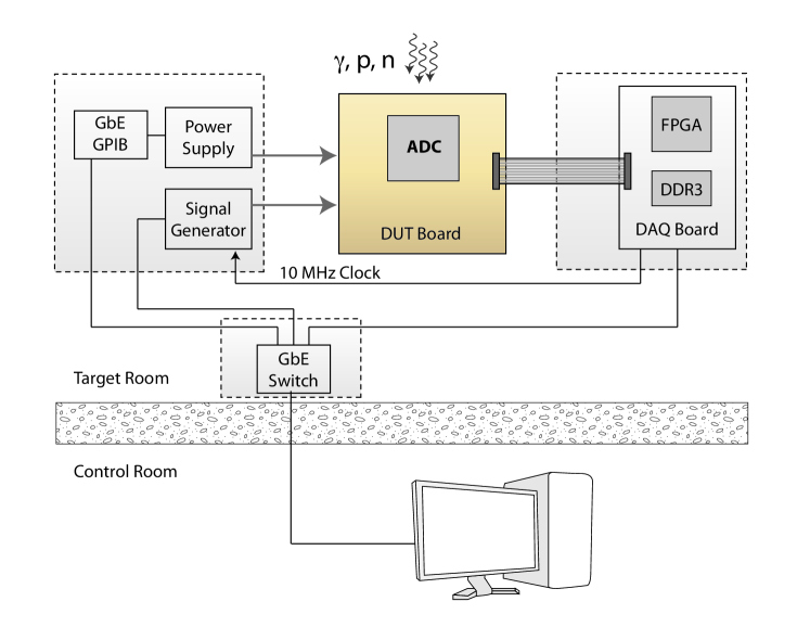
To perform ADC radiation tests we designed and implemented a setup that allows for the dynamical test of ADCs. The setup allows us to examine the ADC output sample by sample to detect radiation induced data modification. A block diagram with the relevant components is shown in Fig. 2. The device under test (DUT) that is exposed to various radiation sources is mounted on the DUT board. Data is acquired by a data acquisition board (DAQ) that is shielded from charged particles and neutrons by a combination of lead and polyethylene blocks. A short high speed extension cable connects the DAQ and DUT boards for fast data transfer. The power supply and signal generator for the device under test are also located in the target room behind shielding. The signal generator is synchronized to the DAQ board. All devices are controlled by a main computer located in the control room via gigabit ethernet connections.
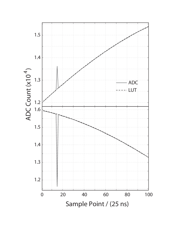
A sine wave of frequency and is fed to the ADC and digitized at 40. To detect the presence of an erroneous output signal, e.g. caused by a single event effect, the digitized signal is compared sample by sample to the expected values obtained from a lookup table. Prior to irradiation the lookup table is generated by an iterative routine which averages digital data to obtain a reference waveform. Later the phase and amplitude are adjusted to match the real time data. During data taking any deviation outside of a preset window triggers the system to record samples around the trigger for later analysis.
4 Response to ionizing dose
Ionizing dose tests are performed to determine the total ionizing dose that renders the components inoperable and to determine their annealing properties. These studies were performed using the source at the Brookhaven National Laboratory Solid State Gamma-Ray Irradiation Facility. DUT boards were placed at a location where the dose rate was 14 krad/h. Dose rates were determined with optically stimulated luminescence (OSL) dosimeters provided and read by Landauer Inc. Results are reported in rad(Si) with an error of [4].
Seventeen ADCs and their response to ionizing dose are presented in Table 1. All of the ADCs tested are manufactured in CMOS technology with a 180 nm feature size, except for one that is manufactured in 350 nm feature size. In this paper the ADC is defined as operational if the ADC output signal is within 5% of the pre-irradiation amplitude, regardless of the the current drawn. However, in most cases what we observed was a sudden failure of the components being irradiated. As table 1 shows that all components withstood doses greater than or equal to 100 kRad, with six performing satisfactorily at doses larger than 1 albeit a power increase of a factor of approximately 2.
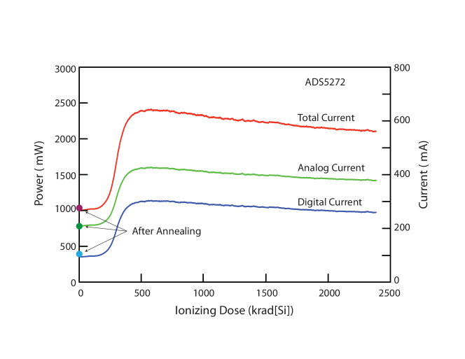
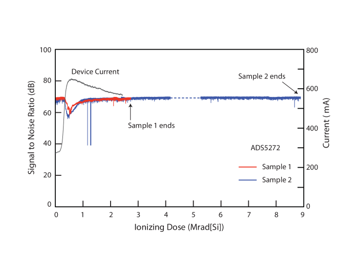
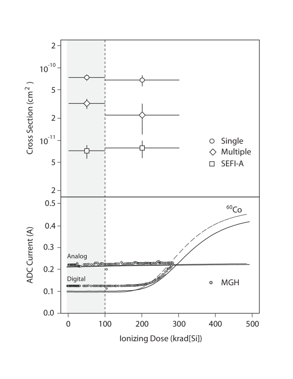
Fig. 3 shows the current increase of the ADS5272 ADC as a function of ionizing dose. The currents for both the analog and digital sections of the ADC rise between 350 and 500 krad. At the higher doses the current slowly decreases. The ADS5272 continues to digitize with acceptable signal to noise ratio as shown in Figure 4. However, we note that the high current consumption makes its use impractical as it would require a power supply able to handle this large excursion.
After irradiation, the ADC sample was annealed at for a period of 24 h. The ADC recovered its original power consumption as indicated in Fig. 3. Room temperature annealing has yielded similar results.
Given the performance of ADS5272, we performed controlled annealing tests with twenty additional samples. We limited the maximum dose to 55 krad, irradiating the components at 14 krad/h, since this is the qualifying dose of a component for the high luminosity LHC located in the detector outer layers. At this value the device current increases by 1.3 %. The components were then annealed at room temperature for 168 hours, followed by additional annealing at 100 for 168 hours. Both the analog and digital currents returned to within 0.5% of the pre-irradiation values. This result shows that the ADS5272 has good annealing properties. This observation is also an indication that this device is likely to be immune to enhanced low dose rate sensitivity (ELDRS).
During ionizing tests we also determined that the ADS5272 exhibits small gain changes. For total integrated doses below 200 krad, the gain change is linear with a slope of -0.015%/krad. Above 200 krad the ADS5272 gain changes by 3%. Similar measurements were performed for the ADS5294 which has a similar response to ionizing radiation. The ADS5294 has a smaller gain change at -0.007%/krad for total ionizing doses below 200 krad.
| ADC | Dynamic | F | Analog | Channels | per | Feature | Vendor | TID |
| Range | Input Span | per Chip | Channel | Size | ||||
| [] | [] | [] | [] | (nm) | [] | |||
| AD9265-80 | 16 | 80 | 2 | 1 | 210 | 180 | ADI | 220 |
| AD9268-80 | 16 | 80 | 2 | 2 | 190 | 180 | ADI | 160 |
| AD9269-40 | 16 | 40 | 2 | 2 | 61 | 180 | ADI | 120 |
| AD9650-65 | 16 | 65 | 2.7 | 2 | 175 | 180 | ADI | 170 |
| AD9253-125 | 14 | 125 | 2 | 4 | 110 | 180 | ADI | 105 |
| LTC2204 | 16 | 40 | 2.25 | 1 | 480 | 350 | Linear | 180 |
| LTC2173-14 | 14 | 80 | 2 | 4 | 94 | 180 | Linear | 105 |
| LTC2193 | 16 | 80 | 2 | 2 | 125 | 180 | Linear | 100 |
| ADS4245 | 14 | 125 | 2 | 2 | 140 | 180 | TI | 235 |
| ADS6445 | 14 | 125 | 2 | 4 | 320 | 180 | TI | 210 |
| ADS5282 | 12 | 65 | 2 | 8 | 77 | 180 | TI | 460 |
| ADS5263 | 16 | 100 | 4 | 4 | 280 | 180 | TI | 2100 |
| ADS5294 | 14 | 80 | 2 | 8 | 77 | 180 | TI | 1070 |
| ADS5292 | 12 | 80 | 2 | 8 | 66 | 180 | TI | 1060 |
| ADS5272 | 12 | 65 | 2.03 | 8 | 125 | 180 | TI | 8800 |
| HMCAD1520 | 14 | 105 | 2 | 4 | 133 | 180 | Hittite | 2300 |
| HMCAD1102 | 12 | 80 | 2 | 8 | 59 | 180 | Hittite | 1730 |
5 Single Event Upset
It is well known that high energy hadrons () can induce single event effects in semiconductor devices. Unlike heavy ions, ionization in the device’s critical areas is caused by nuclear fragments produced by the interaction of high energy hadrons with the semiconductor nuclei. Thus the probability of single event upset occurrence is the product of the probabilities that a nuclear reaction occurs and that the fragments deposit charge in a susceptible location above the SEU critical threshold.
In an ideal measurement, SEU cross sections would be determined with hadrons with an energy spectrum identical to the radiation environment where the component will be used. This guarantees that the multiplicity and the energy of nuclear fragments is accurately reproduced. Experimentally, this is seldom possible. The best approximations to the particle spectrum presented in Fig. 1 are neutron sources attainable at LANSCE at Los Alamos or TSL at Uppsala [5, 6]. Particle fluxes at these facilities are appropriate for devices with larger cross sections () such as RAM memories and less suitable for devices with small cross sections such as an ADC. For ADCs an alternative is to measure the SEU cross sections using high energy, high flux proton beams. The drawbacks are that the actual cross sections will be different than for the expected radiation environment and a large ionizing dose is also deposited in the devices during SEU measurements. In practice proton facilities are useful to measure processes with cross sections of in few hours, whereas WNR-LANSCE is limited to that is achievable in 24 hours.
5.1 Irradiations
| Component | Facility | Energy | Total Fluence | Total Dose | NIEL | Channels Read |
|---|---|---|---|---|---|---|
| (MeV) | krad | |||||
| ADS5272 | IUCF | 205 | 338 | 1 | ||
| IUCF | 205 | 324 | 1 | |||
| IUCF | 205 | 232 | 1 | |||
| ADS5272 | MGH | 216 | 374 | 8 | ||
| MGH | 216 | 226 | 8 | |||
| MGH | 216 | 132 | 8 | |||
| ADS5272 | LANSCE | 800 | 1 | 1 | ||
| ADS5294 | MGH | 216 | 86 | 8 | ||
| MGH | 216 | 217 | 8 |
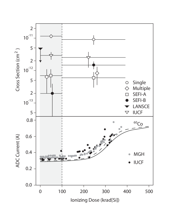
The two high energy proton facilities used to study single event effects are the Francis H. Burr Proton Therapy Center at Massachusetts General Hospital (MGH) [7] located in Boston, Massachusetts and the Indiana University Cyclotron Facility (IUCF) [8] located in Bloomington, Indiana. The MGH is a 216 MeV proton beam facility with flux that can be tuned from to for a circular beam spot size of approximately 2.5 cm in diameter and a variance in flux of approximately 10% across the spot [7]. 216 MeV protons lose energy in silicon at a rate of that translates into an ionizing dose of rad(Si) per incident proton. The IUCF is a 205 MeV proton facility with a nominal flux of . The beam spot is circular with a diameter of 2.5 cm. A similar computation for ionizing dose can be done for the IUCF resulting in rad(Si) per incident proton. The flux at both facilities is obtained from the accelerator staff and has a 5% uncertainty. Shown in the bottom panel of Fig. 5 are the changes in the ADC current as a function of the dose as measured at IUCF, MGH, and facilities.
Measurements with high energy neutrons were performed at the WNR-LANSCE facility. This facility provides neutron beams with an energy distribution that mimics the terrestrial neutron energy spectrum. The dosimetry at LANSCE is known to 15%. We found that during neutron irradiations, secondary charge particles produced in air or other materials upstream of the DUT deposit over the length of the campaign. This was determined by placing passive dosimeters on the components being irradiated.
Proton and neutron irradiations induce displacement damage (NIEL) due to the elastic scattering with moving the atoms from lattice sites into interstitial sites. The conversion of proton or neutron fluence to 1 MeV equivalent neutron fluence can be calculated by [13]:
| (1) |
where is the damage function for a hadron of energy E, and is the fluence of hadrons at a given energy . It is generally accepted that [13]. Since all proton irradiations were performed with mono-energetic beams with , only the value for is needed for the evaluation of the 1 MeV neutron equivalent fluence.
Values for can be obtained from the literature [14, 15, 16, 17] giving an average value for . For neutrons Eq. 1 is used with from the ASTME tables complemented with tables from the work of Huhtinen et al. at high energies[13, 16].
Table 2 summarizes the exposures performed for the measurements of SEU cross sections. From the above considerations both the total ionizing dose and 1 MeV neutron equivalent fluence are listed. The value calculated for LANSCE is for a particle spectrum provided by the accelerator staff. The provided spectrum does not include neutrons with energy below 1 MeV, and therefore we are neglecting the contribution of lower energy neutrons. Since the damage function is very low below 0.5 MeV we don’t expect a significant contribution in the estimated 1 MeV equivalent fluence. All values are considered below fluences where the onset of displacement damage becomes noticeable in CMOS devices.
5.2 SEE studies
Two categories of SEE that influence the functionality of an ADC are data corruption and functional interrupt. Corrupted data leads to wrong information and single event functional interrupt (SEFI) on the other hand will lead to a longer dead time due to the need to reset or re-initialize the ADC. We chose to study in detail single event effects in two candidate ADCs, the ADS5272 and the ADS5294. Both ADCs have eight channels with 12 and 14 bit digitization respectively. The ADS5272 is the simpler device with only few user programmable registers. The ADS5294 is a newer generation ADC with 37 user accessible configuration registers providing the user with a greater flexibility.
For both ADCs we have identified various types of single event effects that we classify in three categories. The single event effect most commonly observed are transients (corrupted data) as shown in Fig. 6. The effect is a change in a bit or bits in a digital word which lasts for one clock cycle. The second type is a SEFI (defined as SEFI-A) that can be cleared by reprogramming the user registers. The third is also a SEFI (defined as SEFI-B) which requires a power cycle to reinitialize the device. In analyzing the data we have noticed that the SEFI-B cross section is dose dependent and hence we give the cross sections for doses below and above 100 krad of integrated dose.
5.2.1 ADS5272
The ADS5272 was tested in two configurations. Experiments conducted at LANSCE and IUCF were performed by monitoring one ADC channel from a total of eight. The data set obtained from irradiation campaigns at MGH was performed by reading all eight channels. In all runs, single event transient (SET) cross sections were determined for events where the difference between the actual ADC readout and expected value was larger than 31 mV or 64 ADC counts. It should be noted that the cross section for SETs is larger than for SEFIs. In order to increase the number of SEFIs detected two exposures where the difference was set to 500 mV, (1024 ADC counts) were performed. With less time spent recording SET events, this strategy allow us to focus mostly on functional interrupts that happens outside of the data stream. In total we have irradiated six ADCs in high energy proton beams, and one in the white energy spectrum neutron beam.
The top panel of figure 5 shows the cross sections determined from the various runs. The largest cross section observed is for the process where one upset occurs in one of the eight ADC channels. The measurement from the IUCF runs is times lower than when all eight channels are read. The exposure at LANSCE yielded no events and therefore we only quote the upper limit for this measurement. Our analysis also shows that of transient events happen in more than one channel simultaneously. These could be caused either by simultaneous bit upsets across channels or an upset elsewhere in the ADC control logic.
The SEFI cross sections are lower in value. SEFI-A is more frequent than SEFI-B for the region of total ionizing dose lower than 100 krad. SEFI-A in this device can be cleared in 1.6 by reprograming four user registers. Above 100 krad we observe an increase in the SEFI-B cross section by a factor of which is greater than SEFI-A cross section. This type of effect has been observed previously in different devices with notable differences in cross sections as a function of deposited dose [9, 10, 11, 12]. Cross sections for SEFI-A remains constant.
5.2.2 ADS5294
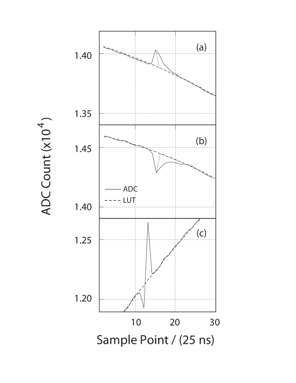
The ADS5294 is a 14 bit ADC with 37 user configurable registers. It is a device that is significantly different than ADS5272. The results for ADS5294 are shown in Fig. 7. The upper panel shows the SEU cross sections measured with high energy protons at MGH, and with a detection threshold set to 125 mV or 1024 ADC counts. Detailed analysis shows that % of upsets correspond to a positive rising signal, % have a negative going signal, and we find that a small fraction of events are bipolar glitches, %. The analysis also shows that both positive and negative transients have respectively 16% and 10% of signals that take 4 to 5 clock cycles to return to baseline. Examples of these types of transients together with bipolar transitions are depicted in Fig. 8. The origin of this type of single event upset is unknown. We examined the possibility that these signals are pick-ups from nearby equipment, or the accelerator itself. We did not find any evidence that these are induced RF signal in our setup. Moreover no signals similar to these were observed during the irradiation of ADS5272 in the same facility.
The measured SEFI-A cross section is approximately one order of magnitude larger than for ADS5272, which is probably due to a more complex configuration logic implemented in this ADC. In 70% of SEFI-A case are instances where we observe a sudden gain change or a constant output equal to the ADC value when the upset happened or a null ADC output. The remaining 30% of cases are those where the ADC output shows an oscillatory output, or a distorted output signal. All SEFI-A events can be cleared in by reprogramming the user configurable registers. We did not observe any dose dependence on measured SEFI cross sections. No associated SEFI-B was observed in this ADC.
6 Summary and Discussions
This paper reports on the qualification of commercial off the self analog to digital converters for use in accelerator radiation environments. For the test and qualification, we have developed an elaborate setup that permits us to check sample by sample if a digitized output word has been corrupted by radiation. To achieve this, the experimental setup compares each digitized signal with a lookup table containing the expected outcome. The experiment was designed having in mind the detection of single event upsets that last one clock cycle. This detection method is limited only by the system noise. Using this setup we thoroughly tested two ADCs the ADS5272 and ADS5294. They were chosen from a total of seventeen candidates that withstood at least 100 krad of ionizing radiation. These candidates also have desirable features such as effective number of bits, digitization frequency and latency. These are qualities that are desirable for use in high energy physics experiment.
The ADS5272 showed an exceptional recovery during annealing tests after ionizing radiation. Twenty samples were subjected to 55 krad total ionizing dose typically showing a gain change of 1.3%. After irradiation the devices were annealed at room temperature and 100 ∘C and returned to the pre-irradiation values to within 0.5%. This makes this ADC suitable for use in applications where there are extensive down-times, which is the case for the large hadron collider. It is also worth noting that the response to ionizing radiation is the same regardless of the radiation source. Both proton and irradiations induce the same response per unit dose on both the ADS5294 and the ADS5272. Unlike gamma rays, high energy protons also induce displacement damage. We estimate that the ADCs were exposed to 1 MeV neutron equivalent fluence. Although displacement damage is not expected to cause effects until much higher fluences in CMOS devices, the observation that the responses are nearly identical when comparing and proton irradiations reassure us that there is little effect from displacement damage.
| SEU Type | ADS5272 | ADS5272 | ADS5294 | ADS5294 |
|---|---|---|---|---|
| (<100 krad) | ( >100 krad) | (<100 krad) | (>100 krad) | |
| Upset in a single channel | ||||
| Upset in multiple channels | ||||
| SEFI A | ||||
| SEFI B | – | – |
Either ADC is well suited for use in the outer layers of high energy physics detectors where the expected ionizing dose is low. To use these devices the challenge is to implement mitigation strategies that will either reduce or eliminate SEEs to an acceptable level. For ADCs the main problem is not SETs that produce bit flips but the single event functional interrupts, SEFIs. They require a more sophisticated mitigation techniques.
To estimate the SEU rates in a real application, we take the values of the cross sections listed in table 3 and apply them to the ATLAS liquid argon calorimeter environment. At the position where the electronic boards are located, the expected fluence of hadrons with is over a period of 10 hours. The system uses 2500 ADCs to digitize the liquid argon calorimeter trigger signals. Under these assumptions the number of upsets for this period for both ADCs are presented in Table 4 including a safety factor of 2. The expectation is that for the entire calorimeter 0.6 SEFI-B will be observed in the 10 hours of running. In the table we also include the typical times required to reset the effect of the upset. For the LHC it is clear that any long intervention, such as a power recycle, can be made at the end of each fill period. In addition, the LHC revolution includes one period of 3 duration with no collisions every 88.924 . This short gap can be used to mitigate SEFIs, for example SEFI-A in ADS5272. In the end, at least for this case, the penalty paid is that in average one debilitating SEFI will happen approximately every 20 hours of LHC operation at full luminosity and it will be the experimenter’s judgment if this rate is acceptable.
| SEU Type | ADS5272 | Recovery | ADS5294 | Recovery |
|---|---|---|---|---|
| time | time | |||
| Upset in a single channel | 34 | 25 ns | 205 | 25 ns |
| Upset in multiple channels | 2 | 25 ns | 91 | 25 ns |
| SEFI A | 2 | 1.6 | 20 | 5 |
| SEFI B | 0.6 | on/off | 0 | – |
There are uncertainties in the estimates of SEU rates that come from multiple sources. First, The SEU rates are based on measurements performed with mono-energetic protons. In reality the energy spectrum of particles that compose the environment shown in Fig. 1, is closer to the cosmic ray produced neutrons, similar to the LANSCE facility. Seifert et al. [18], have compared cross sections determined with mono-energetic protons and with the neutron energy spectrum at LANSCE finding that protons consistently give a larger cross section by a factor of 1.5 to 2.0. The second source that applies to the SEFI-B in ADS5272 is the dependence of the cross section on ionizing dose. This type of dependence has been observed previously and could imply that for a background dominated by neutrons may have a much lower cross section than what is measured with protons. The third source of uncertainty comes from the fact that we maybe overlooking the possibility of SEU induced by the thermal neutron capture reaction [19, 20]. Depending on the doping concentration of p-type Silicon, and the flux of thermal neutrons this reaction may induce significant numbers of SEU. These sources of uncertainty can influence the SEU rates and proper safety factors must be considered.
We have shown that COTS ADCs can be used in the accelerator radiation environment. In particular, the ADS5272 and ADS5294 are well suited for use in the external layers of high energy physics experiments. They are appropriate for integrated ionizing doses of up to 200 krad, and show very good recovery during annealing periods. For the design of electronics the main challenge is to design a mitigation strategy for single events that is acceptable to the experimenter. We discussed the use of pre-determined time intervals in the large hadron collider beam structure that can be used to mitigate some of functional interrupts. As new ADCs are offered by vendors every year, a program to evaluate their susceptibility to radiation may reveal more ADCs candidates that can be used in the accelerator environment.
Acknowledgements.
We acknowledge the excellent service and help provided by Mr. E. Cascio at the MGH facility, Dr. B. von Przewoski at IUCF and Dr. S. Wender at LANSCE. Their expert guidance was invaluable in the execution of single event upset tests. This work was supported in part by the Unites States Department of Energy Contract No. DE-AC02-98CH10886.References
- [1] P. S. Winokur et al., Use of COTS microelectronics in radiation environments, IEEE Transactions on Nuclear Science ,vol. 46 , (1999) 1494 - 1503.
- [2] M. Bosman, I. Dawson, V. Hedberg and M. Shupe ATLAS radiation background task force summary document, retrieved from http://atlas.web.cern.ch/Atlas/GROUPS/PHYSICS/RADIATION/RadiationTF_document.html
- [3] M. S. Gordon, P. Goldhagen, K. P. Rodbell, T. H. Zabel, H. H. K. Tang, J. M. Clem, and P. Bailey, Measurement of the Flux and Energy Spectrum of Cosmic-Ray Induced Neutrons on the Ground, IEEE Transactions on Nuclear Science, vol. 51 (2004) 3427-3434
- [4] Landauer Inc., Online: http://www.landauer.com/
- [5] B. Gersey, R. Wilkins, H. Huff, R. Dwivedi, B. Takala, J. O. O’Donnell, S. A. Wender, R. C. J. Singleterry, Correlation of neutron dosimetry using a silicon equivalent proportional counter microdosimeter and SRAM SEU cross sections for eight neutron energy spectra. IEEE Trans. Nucl. Sci. vol. 50 (2003) 2363 2366.
- [6] A. V. Prokofiev, S. Pomp, J. Blomgren, O. Bystrom, C. Ekstrom, O. Jonsson, D. Reistad, U. Tippawan, D. Wessman, V. Ziemann, M. Osterlund, A new neutron facility for single-event effect testing, Reliability Physics Symposium, 2005. Proceedings. 43rd Annual. 2005 IEEE International, pp. 649-695
- [7] Ethan. W. Cascio, Janet. M. Sisterson, Jacob B. Flanz, and Miles. S. Wagner, The Proton Irradiation Program at the Northeast Proton Therapy Center, 2003 IEEE Radiation Effects Data Workshop, (2003), 141 - 144
- [8] M.E. Rickey, M.B. Sampson, The Indiana University cyclotron facility, Nuclear Instruments and Methods, Volume 97, Issue 1, 15 November 1971, Pages 65-70
- [9] M. A. Xapsos, L. W. Massengill,W. J. Stapor, P Shapiro, A. B. Campbell, S. E. Kerns, K. W. Fernald and A. R. Knudson, Single-Event, Enhanced Single-Event and Dose-Rate Effects with Pulsed Proton Beams, IEEE Trans. Nuc. Sci, NS-14, 1419,(1987)
- [10] J. R. Schwank, M. R. Shaneyfelt, J. A. Felix, Member, G. L. Hash, V. Ferlet-Cavrois, P. Paillet, Member, J. Baggio, P. Tangyunyong, and E. Blackmore, Issues for Single-Event Proton Testing of SRAMs, IEEE Trans. Nuc. Sci., VOL. 51, NO. 6, December 2004.
- [11] N. Seifert, B. Gill, S. Jahinuzzaman, J. Basile, V. Ambrose, Quan Shi, R. Allmon and A. Bramnik, Soft Error Susceptibilities of 22 nm Tri-Gate Devices, IEEE Trans. Nuc. Sci., Vol. 59, 6, pp. 2666-2673, 2012.
- [12] S. Jahinuzzaman, B. Gill, V. Ambrose and N. Seifert, Correlating low energy neutron SER with broad beam neutron and 200 MeV proton SER for 22nm CMOS Tri-Gate devices IEEE IRPS pp. 3D.1.1-3D.1.6, 2013
- [13] ASTM E722 - 09e1 Standard, Standard Practice for Characterizing Neutron Fluence Spectra in Terms of an Equivalent Monoenergetic Neutron Fluence for Radiation-Hardness Testing of Electronics, October, 2009.
- [14] A. Akkerman, J. Barak, M.B. Chadwick, J. Levinson, M. Murata, and Y. Lifshitz, Updated NIEL calculations for estimating the damage induced by particles and -rays in Si and GaAs Radiation Physics and Chemistry 62 (2001) 301-310
- [15] Insoo Jun, Michael A. Xapsos, Scott R. Messenger, Edward A. Burke, Robert J. Walters, Geoff P. Summers, and Thomas Jordan, Proton Nonionizing Energy Loss (NIEL) for Device Applications IEEE Transactions on Nuclear Science, Vol. 50, No. 6, (2003) 1924
- [16] M. Huhtinen and P.A. Aarnio, Pion induced displacement damage in silicon devices Nucl. Instr. Meth. In Phys. Res. A, vol 335, pp 581-582, 1993.
- [17] G. R. Hopkinson, C. J. Dale, and P. W. Marshall, Proton Effects in Charge-Coupled Devices IEEE Transactions on Nuclear Science, vol. 43, No. 2, (1996) 614
- [18] N. Seifert, S. Jahinussaman, J. Basile, Q. Shi, R. Allmon and A. Braknik, Soft Error Susceptibilities of 22 nm Tri-Gate Devices, IEEE Trans. on Nucl. Science, vol 99, No. 6 (2012) 2666- 2673
- [19] A Vazquez-Luque, J. Marin, J.A. Terron,, M. Pombar, R. Bedogni, F. Sanchez-Doblado and F. Gomez. Neutron Induced Single Event Upset Dependence on Bias Voltage for CMOS SRAM With BPSG, IEEE Trans. on Nuclear Physics, vol. 60, (2013) 4692 - 4696
- [20] Yutaka Arita, Mikio Takai, Izumi Ogawa and Tadafumi Kishimoto, Experimental Investigation of Thermal Neutron-Induced Single Event Upset in Static Random Access Memories, Japanese. J. Appl. Phys. 40 (2001) L151 doi:10.1143/JJAP.40.L151.