Surface acoustic wave devices on bulk ZnO crystals at low temperature
Abstract
Surface acoustic wave (SAW) devices based on thin films of ZnO are a well established technology. However, SAW devices on bulk ZnO crystals are not practical at room temperature due to the significant damping caused by finite electrical conductivity of the crystal. Here, by operating at low temperatures, we demonstrate effective SAW devices on the (0001) surface of bulk ZnO crystals, including a delay line operating at SAW wavelengths of and and a one-port resonator at a wavelength of . We find that the SAW velocity is temperature dependent, reaching km/s at 10 mK. Our resonator reaches a maximum quality factor of , demonstrating that bulk ZnO is highly viable for low temperature SAW applications. The performance of the devices is strongly correlated with the bulk conductivity, which quenches SAW transmission above about 200 K.
I Introduction
Surface acoustic waves (SAWs) are mechanical wave modes confined to the surface of a material. In piezoelectric materials, a SAW is accompanied by an electric field and can thus be used for implementing electrical signal processing devices such as filters and oscillators, widely used in telecommunications Morgan (2007). The response of a SAW device can also be very sensitive to external parameters such as temperature, pressure or mass loading of the surface, making them excellent candidates for a variety of sensors including biosensors, in which a functionalised surface binds to specific molecules Länge, Rapp, and Rapp (2008).
SAWs are usually excited by means of a periodic AC electric field, requiring a piezoelectric material to be present to couple electric field to mechanical stress. Two configurations are commonly deployed: either the material (bulk) substrate is piezoelectric, or a thin layer of a piezoelectric material is deposited onto a non-piezoelectric substrate. To excite a SAW, an oscillating voltage of frequency is applied to an interdigital transducer White and Voltmer (1965) (IDT) whose spacing determines the wavelength , such that . The SAW velocity is in the range for commonly used single-crystal materials Morgan (2007) but can reach for layered systems Nakahata et al. (2003); Lin et al. (2007). The IDT also works as a receiver, generating an oscillating voltage when a SAW of the right wavelength passes through it Morgan (2007). A SAW reflector similar to an optical Bragg mirror may be implemented by a metal grating or grooves in the surface. Using these components, it is possible to construct delay lines (by spatially separating transmitting and receiving IDTs) and resonators (by enclosing an IDT between two reflectors Morgan (2007); Bell D.L.T. and Li (1976)).
ZnO is a relatively common material in SAW devices, but until now there have only been reports of its use as a thin layer piezoelectric transducer on top of a non-piezoelectric substrate such as sapphire, diamond or SiO2/SiMorgan (2007); Weber, Weiss, and Hunklinger (1991). Wafer scale bulk ZnO has recently become availableLook et al. (1998); Look (2001); Avrutin et al. (2010), but even nominally pure material contains dopants that give rise to a non-zero room-temperature electrical conductivity. This conductivity damps SAWs efficiently, impeding the use of bulk ZnO in SAW devices.
Due in part to the development of bulk crystal growth, ZnO is receiving growing interest as a device material Avrutin et al. (2010); Jagadish and Pearton (2006); Özgür et al. (2005). Its electronic bandstructure, in particular its wide bandgap and large exciton binding energy, make it promising for optoelectronic applications such as ultra-violet light, and exciton based emitters Özgür et al. (2005). ZnO is also less susceptible to radiation damage than similar materials, making it a good candidate for space applications Look (2001). ZnO has also recently been investigated as a possible material to be used in quantum information devices, due to the presence of long lifetime spin defect centres in the crystal George, Edwards, and Ardavan (2013).
In this paper we report measurements of SAW devices on the (0001) plane of high quality bulk wurtzite ZnO MTI . We work at reduced temperatures to freeze out itinerant charge carriers, thereby decreasing the bulk electrical conductivity and the resultant SAW damping. We fabricate the devices using electron beam lithography and liftoff of a 5/50nm Ti/Al evaporated bilayer. We cool the devices down to a lowest temperature of 10 mK using a dilution refrigerator, and measure their frequency response using a vector network analyzer (VNA). We also perform two-contact electrical resistance measurements as a function of temperature on samples cut from the same ZnO wafer, using graphite paste for contacts, and a liquid 4He dewar dipstick fitted with a Cernox thermometer.
II Measurements
We measure delay lines with a short effective path length to measure temperature dependence at high temperatures, where we expect losses to be high. To observe low-temperature effects, we measure an under-coupled high quality resonator that is much more sensitive to any dissipation due to its long effective path length.
II.1 Delay line
The delay line device has two input transducers in parallel, on either side of the centre conductor of a coplanar waveguide input line (see inset of Fig. 1(b)). One operates at a SAW wavelength of and the other at . Each IDT has 20 finger pairs, and at 2 mm separation, there is an identical mirrored transducer for output. This parallel IDT design is used simply for convenience of gathering more data with a single device.
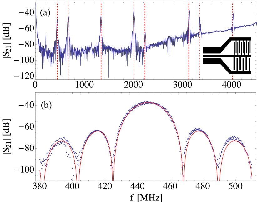
Fig. 1(a) shows the transmission of the delay line, , as a function of frequency at 50 mK. The attenuation of the cables in the cryostat has been subtracted. Both the and transducers are active. We observe multiple transmission peaks, with the fundamentals at MHz (arising from the transducers) and MHz ( transducers), implying a SAW velocity of m/s under the IDTs. We find higher harmonics in the transmission spectrum at , , , , and , demonstrating the possibility to operate bulk ZnO SAW devices up to at least .
Simple interdigital transducers of the kind we use here are expected to give rise to a transmission spectrum close to the fundamental frequency that depends on frequency as
| (1) |
where is the number of IDT fingers, and is the detuning from the center frequency Morgan (2007). Fig. 1(b) shows a measurement of the transmission spectrum close to and a fit to Eq. 1, demonstrating that the behaviour of our device is close to ideal.
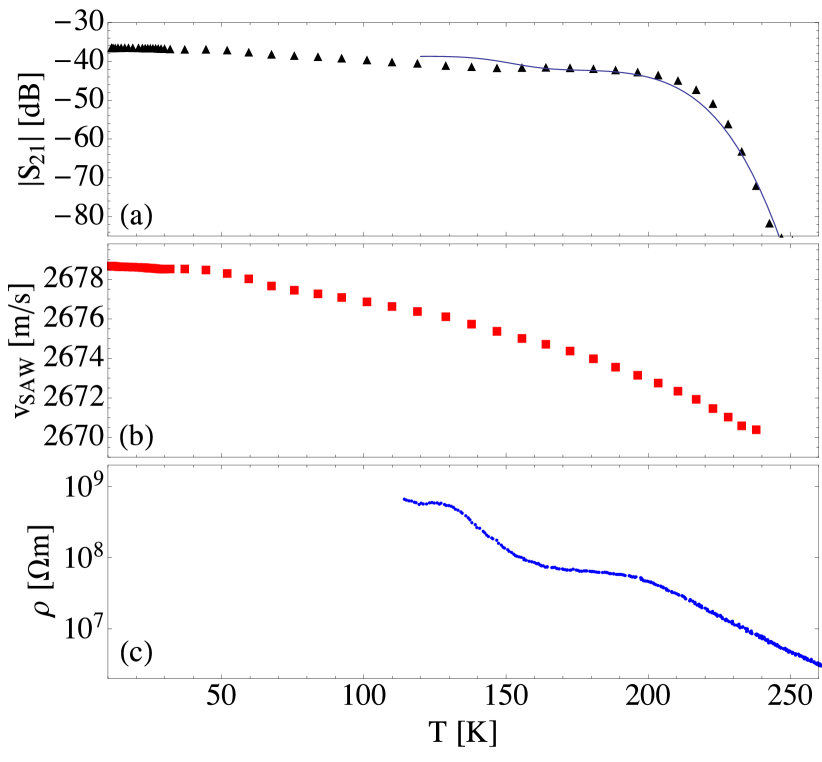
Fig. 2(a) shows the transmission of the delay line measured at as a function of temperature. The temperature dependent attenuation of the cryostat cables has been calibrated out. The delay line transmission is only weakly temperature dependent below 50 K, but drops slowly at higher temperatures up to about 200 K, above which it drops very sharply. This decrease in transmission is accompanied by a shift in ; fitting the transmission to Eq. 1 to obtain at each temperature allows us to derive the change in the SAW velocity with temperature, as shown in Fig. 2(b).
At low temperatures, the ZnO substrate is not electrically conductive. However, at elevated temperatures thermal excitation of impurities leads to -type doping and a non-zero conductivity Özgür et al. (2005). Fig. 2(c) shows the resistivity of our ZnO substrate as a function of temperature. Below about 120 K, the resistance is too high to measure using our apparatus. At higher temperatures, there are several intervals in temperature where the resistivity drops, which may be due to different impurities becoming ionised. These changes in resistivity are correlated with drops in , because the electric field component of the SAW can drive dissipative currents, thereby damping the SAW. The solid line is a fit of the function to the data, where and m are fit parameters. This model assumes that SAW dissipation is linear in the DC conductivity of the ZnO. Deviations from this simple model may be due to the frequency dependent absorption of different defect centres in the crystal.
II.2 Resonator
The resonator has a single IDT with 21 fingers () and is measured in reflection. On either side of the transducer there are passive gratings with 1750 fingers, separated from the IDT by the width of a finger, meaning that there is no discontinuity between the IDT and grating.
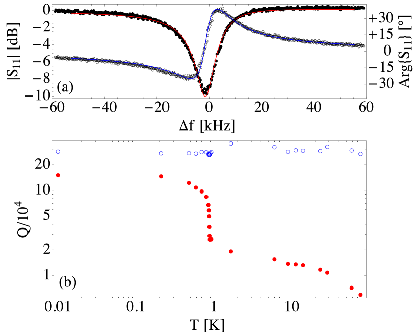
Fig. 3(a) shows the amplitude and phase of the reflection from the one-port resonator as a function of frequency around its resonant frequency of , measured at an input power of and at . In Fig. 3(a), the reflection is normalised to its value far from resonance, and a linear phase shift with frequency (arising from the finite path length of the measurement cables) has been removed. Multiple additional resonances were also observed at nearby frequencies, corresponding to other harmonics of the resonator that lie within the IDT bandwidth (not shown).
As a function of the deviation of the frequency from resonance, the complex reflection coefficient is given by Manenti (2014)
| (2) |
where is the external quality factor (due to the input port coupling), is the internal quality factor (intrinsic to the resonator), is the detuning from the resonance frequency , and is a parameter accounting for the slight asymmetry of the resonance due to impedance mismatches Megrant et al. (2012). The complex data is fitted to Eq. 2 and for the data in Fig. 3(a), the fit yields , and .
Fig. 3(b) shows the dependence of (filled circles) and (empty circles) on temperature. As the temperature increases from its base value, the quality factor decreases, and is particularly strongly temperature dependent as approaches . This dependence is likely to be attributable to quasiparticle scattering in the Ti/Al bilayer, and its transition from the superconducting to normal state at . In contrast, is observed to be approximately temperature independent. Aside from the fixed IDT geometry, is dependent on several properties of the substrate; the dielectric and piezoelectric coupling constants, and Morgan (2007). We can conclude therefore that these properties are not strongly temperature-dependent in this range.
At base temperature, the quality factor reaches values near , which is close to the highest quality factors reported in SAW resonators fabricated on other materials El Habti (1996). It is interesting to note that in our device, superconducting electrodes increase by about a factor of 5.
III Conclusions
We have reported SAW devices on a bulk ZnO crystal substrate. Our results show that bulk ZnO devices are highly feasible at low temperatures, with resonator quality factors among the highest reported, while at high temperature, losses correlate with the bulk DC electrical conductivity. Such high quality SAW devices may find use in low temperature physics research such as quantum information science, where SAWs have already started playing a role Gustafsson et al. (2012, 2014).
IV Acknowledgements
We would like to thank A. Patterson for technical contributions to the project, and A. Landig for measurements of superconducting thin films. This work has received funding from the UK Engineering and Physical Sciences Research Council under grants EP/J001821/1, EP/J013501/1 and EP/G003610/1, and the People Programme (Marie Curie Actions) of the European Union’s Seventh Framework Programme (FP7/2007-2013) under REA grant agreement n [304029]. EBM acknowledges the Clarendon Fund and the Jesus College Old Members Award for financial support.
References
- Morgan (2007) D. Morgan, Surface Acoustic Wave Filters, Second Edition: With Applications to Electronic Communications and Signal Processing (Studies in Electrical and Electronic Engineering) (Academic Press, 2007).
- Länge, Rapp, and Rapp (2008) K. Länge, B. Rapp, and M. Rapp, “Surface acoustic wave biosensors: a review,” Analytical and Bioanalytical Chemistry 391, 1509–1519 (2008).
- White and Voltmer (1965) R. M. White and F. W. Voltmer, “DIRECT PIEZOELECTRIC COUPLING TO SURFACE ELASTIC WAVES,” Applied Physics Letters 7 (1965).
- Nakahata et al. (2003) H. Nakahata, S. Fujii, K. Higaki, A. Hachigo, H. Kitabayashi, S. Shikata, and N. Fujimori, “Diamond-based surface acoustic wave devices,” Semiconductor Science and Technology 18, S96–S104 (2003).
- Lin et al. (2007) C.-M. Lin, T.-T. Wu, Y.-Y. Chen, and T.-T. Chou, “Improved frequency responses of SAW filters with interdigitated interdigital transducers on ZnO/Diamond/Si layered structure,” J. Mech. 23, 253 (2007).
- Bell D.L.T. and Li (1976) J. Bell D.L.T. and R. C. M. Li, “Surface-acoustic-wave resonators,” Proceedings of the IEEE 64, 711–721 (1976).
- Weber, Weiss, and Hunklinger (1991) A. Weber, G. Weiss, and S. Hunklinger, “Comparison of Rayleigh and Sezawa wave modes in ZnO-SiO_2-Si structures,” in IEEE 1991 Ultrasonics Symposium (IEEE, 1991) pp. 363–366.
- Look et al. (1998) D. Look, D. Reynolds, J. Sizelove, R. Jones, C. Litton, G. Cantwell, and W. Harsch, “Electrical properties of bulk ZnO,” Solid State Communications 105, 399–401 (1998).
- Look (2001) D. Look, “Recent advances in ZnO materials and devices,” Materials Science and Engineering: B 80, 383–387 (2001).
- Avrutin et al. (2010) V. Avrutin, G. Cantwell, J. J. Song, D. J. Silversmith, and H. Morkoç, “Bulk ZnO: Current Status, Challenges, and Prospects,” Proceedings of the IEEE 98, 1339–1350 (2010).
- Jagadish and Pearton (2006) C. Jagadish and S. Pearton, eds., Zinc Oxide Bulk, Thin Films and Nanostructures, 1st ed. (Elsevier, Oxford, 2006).
- Özgür et al. (2005) U. Özgür, Y. I. Alivov, C. Liu, A. Teke, M. A. Reshchikov, S. Doğan, V. Avrutin, S.-J. Cho, and H. Morkoç, “A comprehensive review of ZnO materials and devices,” Journal of Applied Physics 98, 041301 (2005).
- George, Edwards, and Ardavan (2013) R. E. George, J. P. Edwards, and A. Ardavan, “Coherent Spin Control by Electrical Manipulation of the Magnetic Anisotropy,” Physical Review Letters 110, 027601 (2013).
- (14) We studied nominally pure single crystal samples obtained commercially from the MTI Corporation, http://mtixtl.com.
- Manenti (2014) R. Manenti, Surface Acoustic Waves for Quantum Information, Ph.D. thesis, University of Oxford (2014).
- Megrant et al. (2012) A. Megrant, C. Neill, R. Barends, B. Chiaro, Y. Chen, L. Feigl, J. Kelly, E. Lucero, M. Mariantoni, P. J. J. O’Malley, D. Sank, A. Vainsencher, J. Wenner, T. C. White, Y. Yin, J. Zhao, C. J. Palmstro̸m, J. M. Martinis, and A. N. Cleland, “Planar superconducting resonators with internal quality factors above one million,” Applied Physics Letters 100, 113510 (2012).
- El Habti (1996) A. El Habti, “High-frequency surface acoustic wave devices at very low temperature: Application to loss mechanisms evaluation,” The Journal of the Acoustical Society of America 100, 272 (1996).
- Gustafsson et al. (2012) M. V. Gustafsson, P. V. Santos, G. Johansson, and P. Delsing, “Local probing of propagating acoustic waves in a gigahertz echo chamber,” Nature Physics 8, 338–343 (2012).
- Gustafsson et al. (2014) M. V. Gustafsson, T. Aref, A. F. Kockum, M. K. Ekström, G. Johansson, and P. Delsing, “Propagating phonons coupled to an artificial atom.” Science (New York, N.Y.) 346, 207–11 (2014).