A Two Qubit Logic Gate in Silicon
Abstract
Quantum computation requires qubits that can be coupled and realized in a scalable manner, together with universal and high-fidelity one- and two-qubit logic gates DiVincenzo2000 ; Loss1998 . Strong effort across several fields have led to an impressive array of qubit realizations, including trapped ions Brown2011 , superconducting circuits Barends2014 , single photonsKok2007 , single defects or atoms in diamond Waldherr2014 ; Dolde2014 and silicon Muhonen2014 , and semiconductor quantum dots Veldhorst2014 , all with single qubit fidelities exceeding the stringent thresholds required for fault-tolerant quantum computing Fowler2012 . Despite this, high-fidelity two-qubit gates in the solid-state that can be manufactured using standard lithographic techniques have so far been limited to superconducting qubits Barends2014 , as semiconductor systems have suffered from difficulties in coupling qubits and dephasing Nowack2011 ; Brunner2011 ; Shulman2012 . Here, we show that these issues can be eliminated altogether using single spins in isotopically enriched siliconItoh2014 by demonstrating single- and two-qubit operations in a quantum dot system using the exchange interaction, as envisaged in the original Loss-DiVincenzo proposal Loss1998 . We realize CNOT gates via either controlled rotation (CROT) or controlled phase (CZ) operations combined with single-qubit operations. Direct gate-voltage control provides single-qubit addressability, together with a switchable exchange interaction that is employed in the two-qubit CZ gate. The speed of the two-qubit CZ operations is controlled electrically via the detuning energy and we find that over 100 two-qubit gates can be performed within a two-qubit coherence time of 8 µs, thereby satisfying the criteria required for scalable quantum computation.
Quantum dots have high potential as a qubit platform Loss1998 . Large arrays can be conveniently realized using conventional lithographic approaches, while reading, initializing, controlling and coupling can be done purely by electrical means. Early research focussed mainly on III-V semiconductor compounds such as GaAs, resulting in single spin qubits Koppens2006 , singlet-triplet qubits Petta2005 and exchange only qubits Medford2013 , which can be coupled capacitively Shulman2012 or via the exchange interaction Nowack2011 ; Brunner2011 . While these approaches demonstrate the potential of quantum dot qubits, strong dephasing due to the nuclear spin background have limited the quality of the quantum operations. A strong improvement in coherence times has been observed by defining the quantum dots in silicon Maune2012 ; Kawakami2014 , which can be isotopically purified Itoh2014 , such that quantum dots with single spin fidelities above the threshold of surface codes Fowler2012 can be realized Veldhorst2014 .
A scalable approach towards quantum computation ideally requires that the coupling between qubits can be turned on and off DiVincenzo2000 , so that single and two-qubit operations can be selectively chosen. Here, we demonstrate this by realizing a CZ gate, which is commonly used in superconducting qubits Barends2014 and has been theoretically discussed for quantum dot systems Meunier2011 . This two-qubit gate, together with single-qubit gates provides all of the necessary operations for universal quantum computation. We can control qubits individually by tuning the qubit resonance frequency via electrical gate-voltage control. When the coupling is turned off, individual qubit operations are performed using a global electron-spin-resonance (ESR) line and the qubits can rely on the long coherence times provided by the nuclear spin-free background Veldhorst2014 . When the coupling is turned on, conditional operations such as the CNOT can be performed, incorporating a CZ gate with operation time 100 ns. From direct measurement of the ESR transitions of the two-qubit system we are also able to fully map out the exchange coupling as a function of detuning.
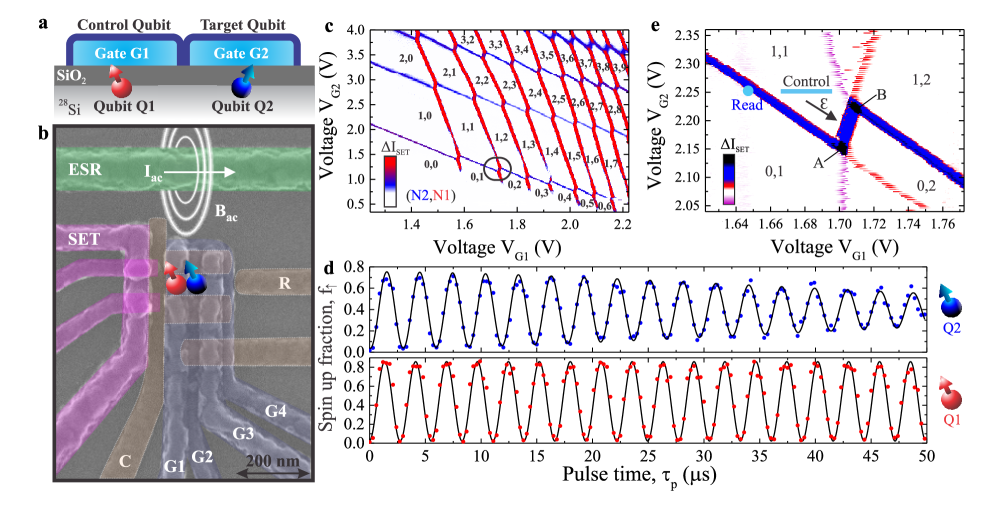
Figure 1a shows a schematic and Fig. 1b shows an SEM-image of the double quantum dot structure fabricated on a 28Si epilayer with a residual 29Si concentration of 800 ppm Fukatsu2003 . The device consists of three aluminum layers, nine aluminum gates, an aluminum lead for ESR control Dehollain2013 , and source, drain and reservoir leads that connect to the gate-induced two dimensional electron gas (2-DEG) using multi-level gate-stack silicon MOS technology Angus2007 . A single-electron-transistor (SET) is formed to monitor the charge state of the quantum dot system and for spin read out using spin-to-charge conversion Elzerman2004 .
Figure 1c shows the stability diagram of the double quantum dot system with charge occupancy (,). The transitions of quantum dot 1, which is underneath gate G1, and quantum dot 2, which is underneath gate G2, can be distinguished by their gate voltage dependence and their capacitive coupling to the SET. When the quantum dot system is depleted to the few-electron regime, the tunnel coupling decreases, partly due to the decrease of the dot size. When dot 2 is empty, the coupling between the reservoir and dot 1 vanishes and the transitions of dot 1 disappear. We define qubit by loading a single electron into dot 1, so that =1, and similarly for qubit we have =1.
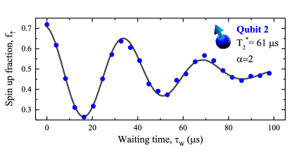
We operate the qubits individually by applying an ac magnetic field at their resonance frequency via the ESR line Veldhorst2014 . Clear Rabi oscillations are observed for both qubits, as shown in Fig. 1d. The visibility of qubit is slightly higher than that of qubit due to the stronger capacitive coupling to the SET. Qubit has a coherence time of = 120 µs, with a that can be extended up to 28 ms using CPMG pulses Veldhorst2014 . Qubit has a slightly shorter coherence time and using a Ramsey experiment we find = 61 µs, comparable to its Rabi decay time (see Supplementary Information section 2). We ascribe this difference to finite coupling of the reservoir to qubit , since we observed that the coherence time increased with decreasing reservoir coupling, achieved by biasing the qubit states further away from the Fermi level in the reservoir.
Spin qubits can be coupled capacitively, as proposed by Taylor Taylor2005 , but here we couple the qubits directly via the exchange interaction as discussed in the seminal work of Loss and DiVincenzo Loss1998 , which is expected to be the mechanism with the faster two-qubit operations. The exchange coupling can be controlled with the detuning energy as depicted in Fig.1e, which controls the energy separation between the and charge states. In Fig.1e, we have lowered the reservoir-dot 2 coupling so that the tunneling time is ~100 µs, which is the coupling during read out in the two-qubit experiments. In this range of weak reservoir-dot 1 coupling, the emptying and filling of dot 1 is hysteretic with gate voltage, since the mutual charging energy becomes relevant, as dot 1 can only tunnel when it aligns in energy with dot 2 Yang2014 . At the nodes of the - crossing (A and B in Fig. 1e), electrons tunnel between dot 1 and the reservoir (via dot 2) and the signal is therefore maximised, whereas in the middle of the transition tunnelling is between dot 1 and dot 2 giving rise to a smaller signal, which is comparable to tunnelling between dot 2 and the reservoir. We control the two-qubit system in the region and read out at the - transition.
The general protocol for the two-qubit operation consists of applying microwave pulses on control qubit and target qubit and voltage pulses to tune the exchange coupling between the qubits, followed by readout on . By exploiting the Stark shift Veldhorst2014 , we electrically control the effective -factor of and , to tune the Zeeman energy and the associated qubit resonance frequency in order to realise individual qubit control. While the spin-orbit coupling in silicon is small Tahan2005 , the valley degeneracy in silicon can complicate the qubit coupling Culcer2010 and even the single-qubit operation Kawakami2014 . However, the presence of a large valley splitting energy in silicon MOS quantum dots Yang2013 ; Veldhorst2014 , combined with a large on-site Coulomb energy compared to the inter-dot tunnel coupling , allows us to neglect all two-particle processes that can occur. We can consequently describe the system in the rotating wave approximation in the basis with the effective Hamiltonian:
| (1) |
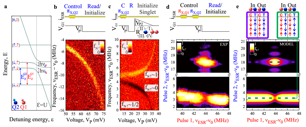
where is the mean Zeeman energy and is the difference in Zeeman energy between the dots, is the detuning energy and for simplicity we have used color coding and set . single-qubit operations are realized with Rabi frequency , by matching the microwave frequency to the resonance frequency of one of the qubits. The presence of exchange coupling between the qubits alters the Zeeman levels as shown in Fig. 2a, where the finite coupling between the qubits causes an anticrossing between the and states. We can now experimentally map out the energy levels in the vicinity of the anticrossing, as shown in Figs. 2b and c. In Fig. 2b, we have initialized and to spin down and by applying a -pulse to we can map out the resonance frequency of as function of detuning. We measure exchange couplings of more than 10 MHz, above which the becomes too short for spin-flips to occur.
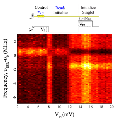
Initialization of the - singlet state is possible by pulsing towards the and returning to the charge state. In this sequence, see Fig. 2c, an electron tunnels from dot 2 to dot 1 (I) followed by an electron tunnelling from the reservoir R to dot 2 (II). After returning to (1,1), the electron from dot 2 tunnels back to R (III), and one of the two electrons on dot 1, which are in a singlet state, tunnels to dot 2 (IV). With this initialization into the singlet state, when we apply a microwave pulse on the spin up fraction is always 1/2, except when the microwave frequency matches a resonance frequency of . Due to the finite exchange interaction, there are two resonance frequencies. The lower frequency rotates the singlet state towards , where always ends up as spin down. The higher frequency rotates the singlet state towards , where always ends up as spin up. The results are depicted in Fig. 2c, showing a decrease in at the lower branch and an increase of at the upper branch, demonstrating an exchange spin funnel, where both branches are visible, as opposed to the single-branch spin-funnel observed in singlet-triplet qubits Petta2005 . In the Supplementary Information we show more detailed sequences of the initialization process, showing that additional levels that mix with the -state can be present at certain detunings.
Having characterized the two-qubit system, we now turn to controlled operations using CROT and demonstrate a CNOT gate, see Figs. 2d and e. In this sequence, the exchange interaction is always on and the resonance frequency of target qubit depends on the -component of , so that there is a resonance frequency where only rotates when is spin up and a resonance frequency where only rotates when is down. We set the exchange coupling such that the two resonance frequencies of are split by 14.5 MHz and apply a -pulse on the control qubit , followed by a -pulse on the target qubit . The experimental results shown in Fig. 2d coincide reasonably with the model shown in Fig. 2e, which includes decoherence. The side lobes of the -pulse can be observed for the to transition, but not for the to transition. We ascribe this difference to the -factor difference between the qubits, which gives a difference in coupling between the and to the -state, see Eq. 1, resulting in a different sensitivity to electrical noise.
The presence of exchange coupling makes the system more vulnerable to electrical noise sources such as electrical gate noise, thereby lowering the coherence time and limiting the amount of possible operations using CROT. However, when the coupling is off, single-qubit fidelities above some fault-tolerant thresholds are possible Veldhorst2014 . We therefore explore a quantum dot CZ gate Meunier2011 ; see Supplementary Information for theoretical considerations on the CZ operation in exchange based systems. This approach allows individual control over the qubits in the absence of interaction and its associated noise, while it uses the coupling to perform two-qubit operations with a frequency that can be much higher than the qubit Rabi rotation frequency, as we will now demonstrate.
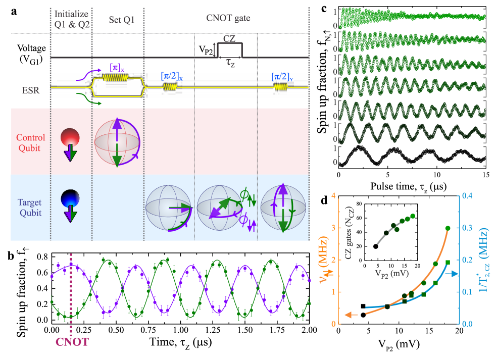
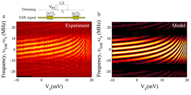
As described by Eq.1 and depicted in Fig. 2a, changing the detuning energy modifies the qubit resonance frequencies of and and introduces an effective detuning frequency , such that one qubit acquires a time-integrated phase shift , see Fig. 3a, that depends on the -component of the other qubit, and vice versa. The exchange coupling and detuning frequency is maximised at the anticrossing , see Fig. 2a. When the exchange is non-zero, SWAP oscillations can also occur, but these are negligible as long as significantly exceeds the effective coupling . When a CZ operation is performed such that , the operation differs only by an overall phase from the basis CZ gate Ghosh2013 . This overall phase can be removed using single-qubit pulses or via voltage pulses exploiting the Stark shift Veldhorst2014 . To realise a CNOT operation using the CZ gate, a CZ() rotation is performed in between two -pulses on that have a phase difference . In Fig. 3a we show the protocol of a CNOT gate for the case that and are equal and opposite, which is when , where conveniently .
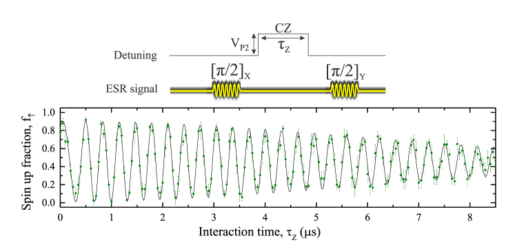
Figure 3b shows the spin-up fraction of after applying a -pulse and a -pulse on separated by an interaction time , with qubit rotated to either or . The resulting exchange oscillations are initially a little slower due to filtering on the pulse line, but after ~300 ns the oscillations approach a constant frequency of 2.4 MHz. The visibility with is slightly less due to preparation errors of . We have fitted the data and we find that the two sequences are out-of-phase ( = -), such that a CNOT gate occurs at = 130 ns, when .
In Fig. 3c we show experiments with different magnitudes of the exchange coupling, set via the detuning . Plotting the frequency as a function of , see Fig. 3d, gives a trend consistent with that observed via ESR mapping, as shown in Figs. 2b and c. The two-qubit coherence time is the free induction decay time of the two-qubit system. At large values of detuning () or when the interaction vanishes (), the two-qubit coherence time simply reduces to the single-qubit Ramsey . We obtain by fitting an exponential to the decay of the oscillations in Fig. 3c. These values of are plotted along with the measured values in Fig. 3d. We find that the two-qubit dephasing rate rises in step with the exchange coupling and , which is to be expected since also increases with , meaning that the qubit system becomes increasingly sensitive to electrical noise. Despite this, the total number of two-qubit operations that can be performed also increases with , as shown in Fig. 3d. In the Supplementary Information we show an optimized sequence where = 8.3 µs and = 3.14 MHz, wich gives the number of two-qubit CZ() gates, 100. This indicates that the error can be less than 1%, corresponding to a fidelity above 99% for the two-qubit CZ gate. The fast two-qubit operation frequency implies also that over CZ gates can be performed within the single-qubit coherence time Veldhorst2014 . Future experiments will move towards devices with reservoirs on each side of the double quantum dot, so that both qubit states can be measured independently, opening the possibillity of full two-qubit tomography and a more detailed assessment of the fidelities.
The tremendeous progress of quantum error correction codes over the last decade has resulted in schemes that allow fault-tolerant quantum computing with single and two-qubit errors as high as 1% Fowler2012 ; values that already seem consistent with the fidelities of these silicon quantum dot qubits. These qubit fidelities could be further improved by lowering the sensitivity to electrical noise. This could be achieved by designing the two-qubit system such that it is completely decoupled from the reservoir during qubit control, possibly by additional pulsing on the barrier gates. Additionally, increasing the inter-dot tunnel coupling will result in a lower at the same , while pulsing simultaneously on qubit top gates G1 and G2 would allow a larger on/off ratio of , so that even faster CZ operations could be performed. Although these silicon qubits represent the smallest scalable two-qubit system reported to date, the complete fabrication process is remarkably compatible with standard CMOS technology, and is also consistent with current transistor feature sizes, offering the exciting prospect of realising a large-scale quantum processor using the same silicon manufacturing technologies that have enabled the current information age.
Acknowledgments: The authors thank S. Bartlett for useful discussions. The authors acknowledge support from the Australian Research Council (CE11E0096), the US Army Research Office (W911NF-13-1-0024) and the NSW Node of the Australian National Fabrication Facility. M.V. acknowledges support from the Netherlands Organization for Scientific Research (NWO) through a Rubicon Grant. The work at Keio has been supported in part by the Grant-in-Aid for Scientific Research by MEXT, in part by NanoQuine, in part by FIRST, and in part by JSPS Core-to-Core Program.
Author contributions: M.V., C.H.Y. and J.C.C.H. performed the experiments. M.V. and F.E.H. fabricated the devices. K.M.I. prepared and supplied the 28Si epilayer wafer. W.H., J.P.D., J.T.M., S.S and A.L. contributed to the preparation of the experiments. M.V. C.H.Y. A.M. and A.S.D designed the experiment and discussed the results. M.V. analysed the results. M.V. and A.S.D. wrote the manuscript with input from all co-authors.
The authors declare no competing financial interests.
Correspondence should be addressed to:
M.V. (M.Veldhorst@unsw.edu.au) or
A.S.D.(A.Dzurak@unsw.edu.au).
References
- (1) DiVincenzo, D.P. The physical implementation of quantum computation. Fortschr. Phys. 48, 771-783 (2000).
- (2) Loss, D. DiVincenzo, D.P. Quantum computation with quantum dots. Phys. Rev. A 56, 120-126 (1998).
- (3) Kok, P. et al., Linear optical quantum computing with photonic qubits. Rev. Mod Phys. 79, 135-174 (2007).
- (4) Brown, K. R. et al., Single-qubit-gate error below in a trapped ion. Phys. Rev. A 84, 030303 (2011).
- (5) Barends, R. et al., Logic gates at the surface code threshold: Superconducting qubits poised for fault-tolerant quantum computing. Nature 508,500-503 (2014).
- (6) Waldherr, G. et al. Quantum error correction in a solid-state hybrid spin register. Nature 506, 204-207 (2014).
- (7) Dolde, F. et al. High-fidelity spin entanglement using optimal control. Nature Comm. 5, 3371 (2014).
- (8) Muhonen, J.T. et al. Storing quantum information for 30 seconds in a nanoelectronic device. Nature Nanotechnology doi:10.1038/nnano.2014.211 (2014).
- (9) Veldhorst, M. et al. An addressable quantum dot qubit with fault-tolerant fidelity, Nature Nanotechnology doi:10.1038/nnano.2014.216 (2014).
- (10) Fowler, A. Marlantoni, M. Martinis, J.M. Cleland, A.N. Surface codes: Towards practical large-scale quantum computation, Phys. Rev. A 86, 032324 (2012).
- (11) Shulman, M.D. et al. Demonstration of entanglement of electrostatically coupled singlet-triplet qubits. Science 336, 202-205 (2012).
- (12) Nowack, K. C. et al. Single-shot correlations and two-qubit gate of solid-state spins. Science 333, 1269-1272 (2011).
- (13) Brunner, R. et al. Two-Qubit gate of combined single-spin rotation and interdot exchange in a double quantum dot. Phys. Rev. Lett. 107, 146801 (2011).
- (14) Itoh, K.M. Watanabe, H. Isotope engineering of silicon and diamond for quantum computing and sensing applications. ArXiv.1410.3922 (214).
- (15) Koppens,F.H.L. et al. Driven coherent oscillations of a single electron spin in a quantum dot. Nature 442, 766-771 (2006).
- (16) Petta, J.R. et al. Coherent manipulation of coupled electron spins in semiconductor quantum dots. Science 309, 2180-2184 (2005).
- (17) Medford, J. et al. Self-consistent measurement and state tomography of an exchange-only spin qubit. Nature Nanotechnol. 8, 654-659 (2013).
- (18) Maune, B.M. et al. Coherent singlet-triplet oscillations in a silicon-based double quantum dot. Nature 481, 344-347 (2012).
- (19) Kawakami, E. et al. Electrical control of a long-lived spin qubit in a Si/SiGe quantum dot. Nature Nanotechnol. 9, 666-670 (2014).
- (20) Meunier, T. Calado, V.E. Vandersypen, L.M.K. Efficient controlled-phase gate for single-spin qubits in quantum dots. Phys. Rev. B 83, 121403(R) (2011).
- (21) Fukatsu, S. et al. Effect of the Si/SiO2 interface on self-diffusion of Si in semiconductor-grade SiO2. Appl. Phys. Lett. 83, 3897-3899 (2003).
- (22) Dehollain, J.P. Pla, J.J. Siew, E. Tan, K.Y. Dzurak, A.S. Morello, A. Nanoscale broadband transmission lines for spin qubit control. Nanotechnology 24 015202 (2013).
- (23) Angus, S.J. Ferguson, A.J. Dzurak, A.S. Clark, R.G. Gate-defined quantum dots in intrinsic silicon. NanoLett. 7, 2051-2055 (2007).
- (24) Elzerman, J.M. et al. Single-shot read-out of an individual electron spin in a quantum dot. Nature 430, 431-435 (2004).
- (25) Taylor, J.M. et al. Fault-tolerant architecture for quantum computation using electrically controlled semiconductor spins. Nature Phys. 1, 177-183 (2005).
- (26) Yang, C.H. Rossi, A. Lai, N.S. Leon, R. Lim, W.H. Dzurak, A.S. Charge state hysteresis in semiconductor quantum dots. Appl. Phys. Lett. 105, 183505 (2014).
- (27) Tahan, C. Joynt, R. Rashba spin-orbit coupling and spin relaxation in silicon quantum wells. Phys. Rev. B 71, 075316 (2005).
- (28) Culcer, D. Cywinski, L. Li, Q. Xuedon, H. Das Sarma, S. Quantum dot spin qubits in silicon: multivalley physics. Phys. Rev. B 82, 155312 (2010).
- (29) Yang, C.H. et al. Spin-valley lifetimes in a silicon quantum dot with tunable valley splitting. Nat. Comm. 4, 2069 (2013).
- (30) Ghosh, J. et al. High-fidelity controlled gate for resonator-based superconducting quantum computers. Phys. Rev. A 87, 022309 (2013).
Supplementary Information
A Two Qubit Logic Gate in Silicon
Experimental methods
The device is fabricated on an epitaxially grown, isotopically purified 28Si epilayer with a residual 29Si concentration of 800 ppm Fukatsu2003 . Using a multi-level gate-stack silicon MOS technology Angus2007 , three layers of Al-gates are fabricated with a thickness of 25, 50 and 80 nm, separated by thermally grown oxidized aluminum on top of a SiO2 dielectric with a thickness of 5.9 nm. The measurements were conducted in a dilution refrigerator with base temperature =50 mK. DC voltages were applied using battery-powered voltages sources and added through resistive voltage dividers/combiners to voltage pulses using an arbitrary waveform generator (LeCroy ArbStudio 1104). Filters were included for slow and fast lines (10Hz to 80MHz). ESR pulses were delivered by an Agilent E8257D microwave analog signal generator and a 3 dBm attenuator at the 4 K plate. The stability diagrams are obtained using a double lock-in technique (Stanford Research Systems SR830) with dynamic voltage compensation.
All our qubit statistics are based on counting the spin states of the quantum dot. Each data point represents the average of 200 up to 1000 single shot read outs, taken in 5 to 10 sweeps to compensate for small drifts.
Further details on single shot read out can be found in Veldhorst Veldhorst2014 .
1. Device structure
Figure 1a of the main text shows an SEM-image of the device, consisting of a charge sensor, an electron reservoir, an ESR line for qubit control and a quantum dot structure to define the qubits. We use an SET (pink) for charge sensing that is only capacitively coupled to the quantum dot structure (top-gates and barriers gates G1-4 are in blue, the confinement gate C is in brown). The qubits can be loaded and read using the reservoir R (brown) and controlled via the ESR-line (green).
2. Single qubit coherence times
Details of the coherence times of qubit Q1 can be found in Veldhorst Veldhorst2014 . Figure 4 shows Ramsey fringes of qubit Q2, obtained by applying two -pulses separated by a waiting time . We have fitted the data with , where and correct for measurement errors, is the detuning frequency, the waiting time, a phase offset and the dephasing time. With this, we find = 61 µs.
3. Qubit initialization
The qubits can be initialized to the -state by aligning the chemical potential of the reservoir in between the Zeeman splitted levels. Using microwave pulsing it is possible to rotate each qubit to the desired state. However, as shown in Fig. 2c of the main text we can also exploit the -state, see Fig. 1e of the maint text, by applying a to initialize the two-qubit system into a singlet state. In Fig. 5, we show the spin up fraction after applying a -pulse on Q2 with different initialization (changing ) and in the presence of finite interaction. For small the qubit remains in the -state and the spin up fraction is zero, except when on resonance, where it is fully rotated. Note that there is in principle only one resonance, as Q1 is always . At large , the charge state is (1,2). At the end of the -pulse, the electron on N2 tunnels to the reservoir and one of the two electrons on N1 tunnels to N2, such that Q1 and Q2 form a singlet. Applying a -pulse on Q2 results then in a spin up fraction = 1/2, except when on one of the two resonances, where it is rotated to either zero or one. Interestingly, we observe before the -state another crossing ( = 8 mV), where the spin up fraction is similar as pulsing to the -state. This level crossing with the -state is possibly due to an excited orbital or valley state.
3. controlled phase (CZ) operations
Single qubit operations are performed at far detuning, eliminating the noise associated with the exchange coupling. While in principle two qubit operations are possible using ESR-pulses in the presence of exchange coupling, the coupling itself can be used directly to allow fast two-qubit operations. The effect of the exchange coupling strongly depends on the relative values of the Zeeman energies and and the tunnel coupling . In silicon there is a degeneracy in valley, which can have its impact on the operation as well. However, in a regime where the valley splitting , only one valley is relevant. Also, MOS double quantum dots have Coulomb repulsions with on-site energies , such that coupling between the -states and the -states are vanishingly small. Therefore, the system is well described using only single-particle terms (excepth for the on-site Coulomb interaction), resulting in Eq.1 of the main text.
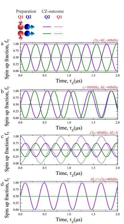
Figure 7 shows the time evolution of the CZ-operations in different parameter regimes. Here, two Rabi pulses with a phase difference = performed at far detuning on the target qubit are separated by a waiting time in the presence of interaction between the two qubits. When , the in-plane oscillations of the target qubit with the control qubit initialized are nicely out-of-phase (Fig. 6a), producing a high fidelity CNOT operation when 100 ns. For other ratios of (Fig. 6b), high fidelity operations can still be obtained by correcting the frequency difference using a different phase = , see Fig. 3 of the main text, between the two Rabi pulses. When the exchange coupling becomes too large with respect to the Zeeman energy difference, the qubits start to make SWAP operations (Fig. 6c), which have to be corrected with more complex pulses. In the extreme that (Fig. 6d), in-plane oscillations occur for only one .
4. XZY-control and CZ-operations
We have explored the CZ-performance using an XZY-pulsing sequence, consisting of an X-pulse and Y-pulse of length and calibrated to have phase difference . The time is fixed to 1.7 µs, equal to a Rabi -rotation. The result is shown in Fig. 6, where the ’upward bending’ of the lines are due to an increase of the in-plane rotation frequency (determined by the detuning frequency and the exchange coupling).
After carefully tuning the qubit, we are able to observe over 25 CZ-oscillations, see Fig. 8. The two-qubit system has a coherence time = 8.3 µs at this exchange coupling resulting in = 3.14 MHz, which corresponds to over 100 CZ()-operations within the coherence time.
References
- (1) Fukatsu, S. et al. Effect of the Si/SiO2 interface on self-diffusion of Si in semiconductor-grade SiO2. Appl. Phys. Lett. 83, 3897-3899 (2003).
- (2) Angus, S.J. Ferguson, A.J. Dzurak, A.S. Clark, R.G. Gate-defined quantum dots in intrinsic silicon. NanoLett. 7, 2051-2055 (2007).
- (3) Yang, C.H. Lim, W.H. Zwanenburg, F.A. Dzurak, A.S. Dynamically controlled charge sensing of a few-electron silicon quantum dot. AIP Advances 1, 042111 (2011).
- (4) Veldhorst, M. et al. An addressable quantum dot qubit with fault-tolerant fidelity, Nature Nanotechnology doi:10.1038/nnano.2014.216 (2014).