Evaporation-driven ring and film deposition from colloidal droplets
Abstract
Evaporating suspensions of colloidal particles lead to the formation of a variety of patterns, ranging from a left-over ring of a dried coffee drop to uniformly distributed solid pigments left behind wet paint. To characterize the transition between single rings, multiple concentric rings, broad bands, and uniform deposits, we investigate the dynamics of a drying droplet via a multiphase model of colloidal particles in a solvent. Our theory couples the inhomogeneous evaporation at the evolving droplet interface to the dynamics inside the drop, i.e. the liquid flow, local variations of the particle concentration, and the propagation of the deposition front where the solute forms an incompressible porous medium at high concentrations. A dimensionless parameter combining the capillary number and the droplet aspect ratio captures the formation conditions of different pattern types.
pacs:
47.15.gm, 47.55.Kf, 47.56.+r, 47.61.JdWhen coffee drops, soup splatter, salted snowmelt or other suspension dries out, the suspended solid remains as a residual stain or pattern. This is the result of a singular evaporative flux at the contact line which is pinned at the substrate Deegan1 . The resulting fluid flow advects particles to the edge where they aggregate, while the fluid itself evaporates. Consequently, single Deegan1 ; Deegan2 ; Deegan3 ; Popov ; Snoeijer1 or multiple rings Kaplan ; Adachi ; Stone2 ; Stone3 ; Chang ; Zhang ; Kaya form in the vicinity of the contact line. In contrast, eliminating the surface roughness of the substrate Snoeijer2 , or drying a suspension of anisotropic colloidal particles Yodh1 , leads to the uniform deposition of particles over the droplet area. Alternatively, the transition from narrow single rings to uniform films can be engineered when the evaporation happens relatively fast Klabunde ; Narayanan ; Bigioni .
To understand the transition between single rings, multiple concentric rings, broad bands, and uniform deposits (Fig. 1(a)), when the contact line of the drying drop (solvent viscosity , interfacial tension ) is pinned to the substrate, we note that in many situations the droplet aspect ratio (Fig. 1(b)). In this limit, the Navier-Stokes equations for fluid flow simplify via the lubrication approximation Oron . At a scaling level, the pressure is determined by Laplace’s law, and the viscous capillary flow speed of the liquid in the radial direction is , with being the evaporation rate, and a dimensionless constant. Then, a balance between the radial pressure gradient and transverse viscous shear implies that . Thus, where is the capillary number, which characterizes the ratio of viscous to capillary forces. When , and the colloids are carried towards the contact line before the drying is complete, so that single ring, concentric rings, or a broad band forms, depending on the initial colloidal volume fraction . When and uniform films form as the solvent rapidly dries before most colloids can reach the droplet edge Bigioni .
During deposition, colloidal particles arriving at the deposition front slow down and stop, while fluid continues to flow through the porous deposit. Hydrodynamically, in the interior of the droplet, the particle concentration is low, and pressure gradients are balanced by viscous stresses in Stokes flow Landau , while in the porous deposit, where the fluid concentration is low, pressure gradients lead to flow through pores governed by Darcy’s law Landau . Thus, we must account for a “Stokes-Darcy transition” to characterize flow in the slender drying droplet as particles are carried by the fluid, before being eventually arrested, while the fluid evaporates away. The form of the residual patterns requires that we also consider the speed of the deposition front relative to the evaporation rate Indeed, the type of patterning is governed by the dimensionless speed at the interface separating the liquid and forming deposit (Fig. LABEL:fig:_schematics(c)). A uniform film forms when is sufficiently large to prevent the liquid meniscus, pinned to the elevated deposit edge, from touching down the substrate. Conversely, lower results in single rings, multiple rings, or broad bands, following meniscus break-up (Fig. 1(e)). The coupling of evaporation-driven flow with a transition from a dilute suspension to porous plug requires a multiphase description of the process.
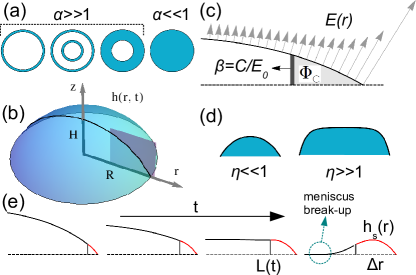
In the lubrication approximation, the depth-averaged solute and solvent velocities are given by and , where and are the local solute and solvent velocities, respectively. The depth-averaged solute volume fraction is , where is the local particle volume fraction, is the depth-averaged solvent volume fraction and is the droplet height (Fig. 1(b)). The growing deposit near the contact line due to the particle accumulation forms a porous plug with a volume fraction of the particle close packing ( for hexagonal packing in three dimensions). To characterize the transition from the Stokes regime for dilute suspensions () to the Darcy regime in the porous medium () we need a model that naturally transitions from one regime to another. A natural candidate is an interpolation between these two linear flow regimes via the Darcy-Brinkman equation Brinkman , which in the lubrication limit reads as
| (1) |
where is the permeability of the porous plug, and the pressure is given by (Fig. 1(d)), with the suspension density, and being gravity. By defining , the mean curvature of the liquid-air interface is given by . When , we would like to ensure that the solute and solvent velocities coincide, i.e. as the particles are advected by the fluid in an approximately Stokesian regime. Beyond the deposition front, as , we would like to ensure that we recover the Darcy regime where the particles are arrested in the porous plug and the fluid velocity is proportional only to the pressure gradient supplemental . A simple closure of Eq. (1) consistent with these limits is Cohen , where the exponent determines the rapidity of the crossover between the two regimes. Eq. (1) in combination with our closure relation, subject to the stress-free and no-slip boundary conditions and yields the depth-averaged velocities
| (2) |
where , with being the effective pore size.
We define a set of dimensionless variables as follows: horizontal coordinate , vertical height , time , velocities , dimensionless pressure , where , is the capillary length, and the dimensionless evaporation rate (Fig. 1(b)). Furthermore, we let be a scaled initial height and the Peclet number with being the solute diffusivity. Dropping the tildes from the dimensionless quantities, and using an axisymmetric polar coordinate system in the rest frame, the depth-averaged scaled equations of local fluid and solute mass conservation are given by
| (3) |
| (4) |
where the scaled liquid flux ( in dimensional units), the particle flux ( in dimensional units), and is the scaled singular form of the local evaporation rate (Fig. 1(c)) along the droplet surface Deegan1 ; Deegan2 . The coupled sixth order system of Eqs. (2)–(4) becomes a boundary value problem for and once appropriate boundary and initial conditions are given.
When the initial droplet aspect ratio is small (). Furthermore, if particle diffusion is negligible (), advection dominates diffusion so that a sharp deposition front forms, and the liquid and solid fluxes in Eqs. (3) and (4) vanish. vanishes at the droplet edge as well, even though the fluid velocity diverges near the contact line, since stays constant there Deegan1 ; Deegan2 ; Deegan3 . Then, Eqs. (2)–(4) reduce to the initial value problem and which yield
| (5) |
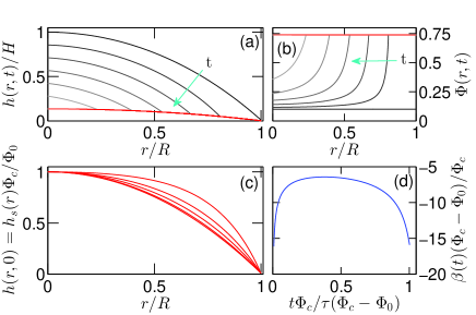
where the initial condition is the hydrostatic height profile given the contact angle at the droplet edge. Locally, evolves only until the critical time (Fig. 2(a)), when the colloids get jammed at the deposition front (see Fig. 1(e)) with (Fig. 2(b)). The deposit height is then fixed at for (Fig. 2(a)). The critical time for jamming is determined from Eq. (5) when Then and are given by
| (6) |
In Fig. 2(c), we show the relation between and as a function of ; both and become more convex close to the contact line as increases, corresponding to an approximate hydrostatically dominated pressure (see Fig. 1(d)).
Having calculated the scaled droplet height , the solid volume fraction and the deposit height we turn to the dynamics of the deposition front location given by the condition . Since all lengths are scaled by the thickness of the droplet , and velocities are scaled by the evaporation rate , in scaled form, the deposition front follows the relation
| (7) |
At taking the reciprocal of both sides of Eq. (7) yields diverges both initially when close to , and at the end of drying when close to (Fig. 2(d)). Thus far we have assumed that solute diffusion is not important, i.e. , but when this is not the case, we have to consider the complete system of equations.
When we need to specify seven boundary conditions over the interval to determine and Three boundary conditions at are given by symmetry: the vanishing particle flux the vanishing liquid flux and the flat meniscus height profile At the deposition front the liquid flux into the deposit at the interface must compensate for the loss of solvent via the evaporation over the deposit height The differential form of this condition in the frame co-moving with the wall at a speed becomes
| (8) |
where Eq. (7) is used to express the spatial derivative in terms of the time derivative. As the colloids are arrested, the particle flux inside the solid vanishes. Therefore, in the moving frame, the particle flux continuity at is given by which yields
| (9) |
The height at the wall between the liquid and the incompressible deposit satisfies in the rest frame. In the moving frame, this condition translates to
| (10) |
We fix the particle volume fraction at the interface as
| (11) |
to extract asymptotically from Eq. (9). Finally, the initial aspect ratio is specified by the hydrostatic height (Fig. 2(c)). The initial particle distribution is given by , where and
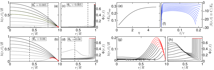
Using the physical parameters N/m, kg/m3, m/s2, m/s, Pas, m2/s Bodiguel and , we find the capillary length m and the time scale s (Fig. 3(e)). Then, , and , so that We choose since the effect of bigger on the formation of rings and bands is insignificant as long as supplemental holds. The exponent is chosen as which models a narrow transition region between the two flow regimes as a function of
We numerically solve Eqs. (2)–(4) subject to the boundary conditions at and Eqs. (8)–(11) at , for the droplet-air interface height , the depth-averaged particle volume fraction , and the deposition front velocity via the COMSOL finite element package Comsol . The divergence of the evaporation rate at the contact line is resolved by assuming when where
In Figs. 3(a)–(b), the time evolution of and are shown in the rest frame. Towards the end of the droplet lifetime, the meniscus reverses curvature and touches the substrate at a location (dashed vertical lines in Figs. 3 (a)–(d), and gray dots as a function of in Fig. 3 (g)), when the evaporation ceases at a time The meniscus touch-down (see Fig. 1(e)), assumed to be axisymmetric footnote1 , is followed by a break-up into two contact lines Kaplan . To regain the equilibrium contact angle deGennes , the contact line closer to moves to the droplet center, whereas the other one will move towards the deposition front and the fluid will be wicked by the jammed colloids.
When narrow rings form with a width (Figs. 3(a), (c)). The magnitude of the front speed , shown in Fig. 3 (f), determines the width supplemental . When increases, increases for all and diverges faster at For single rings, reaches a steady state at early times for For intermediate the particle concentration builds up below , as evidenced by the maxima in at the liquid side of the wall in Figs. 3(d) and (h). When increases, shifts to the droplet center, as demonstrated in Figs. 3(a)–(d), and (g) supplemental . Following meniscus break-up, the inner contact line moves until it is restrained by the meniscus footnote2 , resulting in a new ring. In Fig. 3(b), we show the profiles shortly before the concentric inner ring formation, noting that changes rapidly over the course of drying for bigger When is large, we see the formation of a broad band – Fig. 3(g), with near the contact line, and the touch-down location .
The shape of the band for all is governed by Eq. (10): If the meniscus contact angle at the wall then increases as the band expands (early stages), and would lead to a decreasing height profile (late stages). The combination of the early- and late-stage behaviors result in the curved profiles demonstrated in Figs. 3(a), (b), and (g). The maximum solid thickness is then achieved at the transition between the two regimes (the maxima of the red curves in Fig. 3(g)), as changes curvature due to the evaporation supplemental .
Our multiphase model of an evaporating colloidal droplet describes the different deposition patterns and the transitions between them by accounting for how the droplet evaporates inhomogeneously even as the dilute suspension transitions into a porous plug in the neighborhood of the contact line. We are able to characterize these phenomena in terms of two parameters, the initial concentration and the scaled evaporation rate When we get single rings, multiple rings, and broad bands as increases, while when uniform films assemble over the entire droplet area, consistent with observations. What remains is to understand the deposit thickness and the particle order in it, and will require coupling our multiphase macroscopic theory to a microscopic theory for particulate ordering in dense suspensions.
We thank A. Carlson for fruitful discussions and T. Salez for a critical reading of the manuscript. This research was supported by the Air Force Office of Scientific Research (AFOSR) under Award FA9550-09-1-0669-DOD35CAP and the Kavli Institute for Bionano Science and Technology at Harvard University.
References
- (1) R. D. Deegan et al., Nature 389, 827 (1997).
- (2) R. D. Deegan, Phys. Rev. E 61, 475 (2000).
- (3) R. D. Deegan et al., Phys. Rev. E 62, 756 (2000).
- (4) Y. O. Popov, Phys. Rev. E 71, 036313 (2005).
- (5) Á. G. Marín, H. Gelderblom, D. Lohse, and J. H. Snoeijer, Phys. Rev. Lett. 107, 085502 (2011).
- (6) C. N. Kaplan, N. Wu, S. Mandre, J. Aizenberg, and L. Mahadevan, (submitted).
- (7) E. Adachi, A. S. Dimitrov, and K. Nagayama, Langmuir 11, 1057 (1995).
- (8) L. Shmuylovich, A. Q. Shen, and H. A. Stone, Langmuir 18, 3441 (2002).
- (9) M. Abkarian, J. Nunes, and H. A. Stone, J. Am. Chem. Soc. 126, 5978 (2004).
- (10) S. Maheshwari, L. Zhang , Y. Zhu, and H. C. Chang, Phys. Rev. Lett. 100, 044503 (2008).
- (11) L. Zhang, S. Maheshwari, H-C. Chang, and Y. Zhu, Langmuir 24, 3911 (2008).
- (12) D. Kaya, V. A. Belyi, and M. Muthukumar, J. Chem. Phys. 133, 114905 (2010).
- (13) Á G Marín et al., Proc. Natl. Acad. Sci. USA 109, 16455 (2012).
- (14) P. J. Yunker, T. Still, M. A. Lohr, and A. G. Yodh, Nature 476, 308 (2011).
- (15) X. M. Lin, H. M. Jaeger, C. M. Sorensen, and K. J. Klabunde, J. Phys. Chem. B 105, 3353 (2001).
- (16) S. Narayanan, J. Wang, and X. M. Lin, Phys. Rev. Lett. 93, 135503 (2004).
- (17) T. P. Bigioni, et al., Nature Mat. 5, 265 (2006).
- (18) A. Oron, S. H. Davis, and S.G. Bankoff, Rev. Mod. Phys. 69, 931 (1997).
- (19) Landau LD, Lifshitz EM (2004) Fluid Mechanics, 2nd edition (Elsevier Ltd., Burlington, MA, USA).
- (20) H. C. Brinkman, Appl. Sci. Res. Sect. A 1, 27 (1949).
- (21) See Supplemental Material at XXXX for more information.
- (22) S. I. A. Cohen, and L. Mahadevan, Phys. Rev. Lett. 110, 138104 (2013).
- (23) H. Bodiguel, and J. Leng, Soft Matter 6, 5451 (2010).
- (24) G. Jing, H. Bodiguel, F. Doumenc, E. Sultan, and E. Guerrier, Langmuir 26, 2288 (2009).
- (25) COMSOL 4.3a, Burlington, MA, USA, http://www.comsol.com.
- (26) We ignore local meniscus touch-down due to the irregularities of the substrate, particle adhesion on the surface, and the disjoining pressure of the liquid.
- (27) P. G. de Gennes, F. Brochard-Wyart, and D. Quéré Capillarity and Wetting Phenomena (Springer Science+Business Media, New York, NY, USA).
- (28) The particle aggregate close to the inner contact line in motion may either adhere to the substrate or be dragged by the contact line until it becomes jammed.