Generation and decay of persistent current in a toroidal Bose-Einstein condensate
Abstract
Persistent current, or “flow without friction”, as well as quantum vortices are the hallmarks of superfluidity. Recently a very long-lived persistent flow of atoms has been experimentally observed in Bose-Einstein condensates trapped in a ring-shaped potential. This enables fundamental studies of superfluidity and may lead to applications in high-precision metrology and atomtronics. We overview our recent theoretical studies of the generation and decay of the persistent current in a toroidal atomic Bose-Einstein condensate, and discuss our new investigation of the hysteresis in the atomtronic circuit.
pacs:
03.75.Lm, 03.75.Kk, 05.30.JpI Introduction
The dramatic progress in the field of Bose–Einstein condensates (BECs) of atomic gases continuing last two decades is driven by a combination of new experimental techniques and theoretical advances. Nowadays BECs have become an ultralow-temperature laboratory for nonlinear physics, many-body physics and condensed matter physics, exhibiting superfluidity, quantized vortices, solitons, Josephson junctions and quantum phase transitions. The achievement of Bose–Einstein condensation in dilute atomic gases provided the opportunity to observe and study superfluidity in an extremely clean and well-controlled environment and to search for the subtle links between superfluidity and Bose-Einstein condensation.
Superfluids are distinguished from ordinary fluids by their ability to support dissipationless flow, which is often called persistent current. The existence of a persistent current is related to a stable quantized vortex, which is a localized phase singularity with integer winding numbers. Generation and decay of a persistent current is governed by dynamics of these quantum vortices.
Recently, persistent flow of atoms has been observed in BECs trapped in a ring-shaped potential Ryu et al. (2007); Ramanathan (2011); Ramanathan et al. (2011); Moulder et al. (2012); Beattie et al. (2013); Wright et al. (2013, 2013); Ryu et al. (2013); Neely et al. (2013); Jendrzejewski et al. (2014); Corman et al. (2014); Ryu et al. (2014); Eckel et al. (2014). With a system of laser beams it is possible to create a toroidal condensate and a repulsive barrier rotating around the ring. The presence of a barrier produces a localized region of reduced superfluid density in the condensate annulus – a weak link. A super-fluid ring with a weak link as well as a super-conducting circuit with a Josephson junction can act as a nonlinear interferometer, allowing the construction of high-precision detectors such as superconducting quantum interference devices (SQUID), magnetometers and superfluid gyroscopes. The fast response of the condensate phase winding on the variations in the angular velocity of the barrier is analogous to that in the superconducting current of the SQUID caused by changes in the external magnetic field. This feature makes the atom SQUID ideal for future highly sensitive rotation-measurement devices Ryu et al. (2013).
Ring-shaped Bose-Einstein condensates in toroidal traps are the subject of many experimental and theoretical investigations Kasamatsu et al. (2002); Benakli et al. (1999); Brand and Reinhardt (2001); Das et al. (2012); Martikainen et al. (2001); Modugno et al. (2006) which study persistent currents Ryu et al. (2007); Beattie et al. (2013); Yakimenko et al. (2013), weak links Ramanathan et al. (2011); Wright et al. (2013), formation of matter-wave patterns by rotating potentials Li et al. (2012, 2014), solitary waves Brand and Reinhardt (2001); Mason and Berloff (2009), and the decay of the persistent current via abrupt change of the rotation state (phase slips) Moulder et al. (2012); Piazza et al. (2009, 2013). A persistent atomic flow in a toroidal trap can be created by transferring angular momentum from optical fields Ryu et al. (2007); Wright et al. (2013) or by stirring with a rotating barrier Wright et al. (2013, 2013). These experiments has shown that toroidal geometry makes it possible to avoid the fast vortex splitting that takes place in a singly connected BEC and study the properties of vortices with large winding number.
The present paper is organized as follows. In Section II we briefly review a theoretical treatment Yakimenko et al. (2013) of the remarkable effect in a spinor toroidal BEC, which was recently discovered experimentally in Cavendish laboratory Beattie et al. (2013). In Section III.1 we discuss the analysis of the vortex excitations in a quasi-two-dimensional annular BEC reported in Yakimenko et al. (2014). This work was inspired by the experimental demonstration Wright et al. (2013) of vortices in a toroidal trap, which are excited using a small (diameter less than the width of the annulus) variable-height potential barrier (a “stirrer”). In Section III.2 we briefly overview our recent work Yakimenko et al. (2014), which was motivated by another experiment Wright et al. (2013), where the deterministic phase slips driven by a wide stirrer (rotating weak link) were demonstrated. In Section IV we present our new theoretical results concerning hysteresis effect in two-dimensional ring-shaped condensate. In Section V we make general conclusions.
II Stability of persistent currents in spinor Bose-Einstein condensates
Spinor Bose-Einstein condensates are multicomponent BECs with additional spin degree of freedom. Due to nonsymmetric nature of intercomponent interaction they can demonstrate particularly rich variety of phenomena (for the recent review see Kawaguchi and Ueda (2012); Stamper-Kurn and Ueda (2013)). For two-component BECs in 1D or 2D traps, the stability of the persistent currents and their decay mechanisms were under investigation in Refs. Smyrnakis et al. (2009, 2010); Malet et al. (2010); Kärkkäinen et al. (2007); Jackson and Kavoulakis (2006); Ögren and Kavoulakis (2007); Brtka et al. (2010). Smyrnakis et al. Smyrnakis et al. (2009) concluded that in a strictly one-dimensional ring persistent currents with circulation larger than one are stable only in single-component gases. However, recently Anoshkin et al. (2013), this conclusion was challenged, and it was claimed that persistent currents at higher angular momenta may be stable in certain parameter regions of a two-component system in a 1D ring. In Ref. Bargi et al. (2010) it was found on the basis of mean field calculations and supported by exact diagonalization results, that persistent currents in 2D traps may be stable under specific conditions.
Experimentally such system was investigated recently Beattie et al. (2013) for a toroidally trapped gas of 87Rb atoms in two different spin states. It was discovered in this experiment that the supercurrent is unstable if the spin polarization is below a well-defined critical value and was shown that only the magnitude of the spin-polarization vector, rather than its orientation in spin space, is relevant for supercurrent stability. In Ref. Yakimenko et al. (2013) we have suggest a theoretical explanation of this remarkable effect.
The main properties of an ultracold dilute spin-1 atomic BEC at zero temperature can be accurately described by a set of mean-field Gross-Pitaevskii equations (GPEs) for the spin components of the three-component order parameter . These equations correspond to the Hamiltonian with the spin-independent part (see, e.g. Świsłocki and Matuszewski (2012))
| (1) |
where and is the total density; the strength of interaction between atoms is given in terms of the s-wave scattering length for atom pairs with total spin . The spin-dependent part of the Hamiltonian is given by
| (2) |
where is the Zeeman energy of the state , , and F is the spin density:
where are the spin-1 matrices and .
In accordance with the experimental set-up of Ref. Beattie et al. (2013), we approximate the external toroidal optical trapping potential by a superposition of a harmonic potential with trapping frequency (which models the elliptic highly anisotropic “sheet” beam) and a radial Laguerre-Gauss potential (which models the “tube” beam):
| (3) |
where is the atomic mass, is the radius of the trap (radial coordinate of the minimum of the potential), , and is the trap depth. The parameter corresponds to the topological charge of the optical vortex which produces the Laguerre-Gauss potential.
The harmonic potential creates a tight binding potential in direction, so that the BEC cloud is “disk-shaped” ( with the longitudinal oscillator length). Consequently, we assume that the longitudinal motion of condensate is frozen in:
| (4) |
where . After integrating out the longitudinal coordinates in the GPEs corresponding to the Hamiltonian given in Eq. (1) and (2), and accounting for dissipative effects (see below), we obtain a set of three coupled differential equations in 2D:
| (5) | |||||
| (6) |
with
Here we have introduced the 2D Laplace operator and dimensionless space and time coordinates , , with as well as the dimensionless chemical potential of the spin component . The order parameter takes the form with . Furthermore we define , , and for a 87Rb condensate.
Non-equilibrium dissipative effects are of crucial importance since they provide the mechanism for the damping of the vortices. We describe such effects by the phenomenological parameter on the left hand side of GPEs (5) and (6). Dissipation means that energy and particles are exchanged between the condensate and a thermal reservoir. Here, we use the phenomenological approach introduced by Choi et al. Choi et al. (1998) for atomic BEC in a manner similar to that originally proposed by Pitaevskii Pitaevskii (1959).
The GPEs (5) and (6) with conserve neither the energy nor the number of particles. To simulate realistic experimental behavior of particle number we adjust the chemical potential at each time step so that the number of condensed particles slowly decays with time, , in accordance with measurements for lifetime of atomic BECs reported in Ref. Beattie et al. (2013).
We numerically simulate the dynamics of the persistent flow in a toroidal trap using the two-dimensional dissipative mean-field model given by Eqs. (5) and (6). It turns out that due to the weakness of the spin-dependent part of the interaction and rather significant dissipation, the population remains very low and can be neglected.
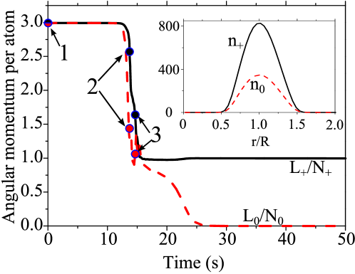
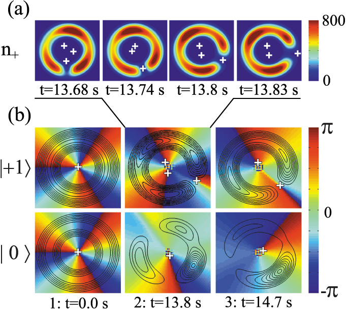
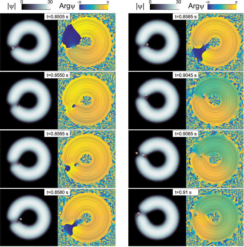
During a phase slip the angular momentum is not integer, as is clearly seen from Fig. 1 which presents a typical example of the temporal dynamics of and spin components of the order parameter. As we observe during a phase slip, the density distribution of the two spin components is highly anisotropic (see Fig. 2(a)). It turns out that the smaller the admixture of the minor component is the more time is needed for the development of the symmetry-breaking azimuthal instability, and thus the longer is the lifetime of the persistent current. This is of no surprise, since the phase separation appears as a result of a repulsive nonlinear inter-component interaction. The phase separation grows out of small azimuthal perturbations which are energetically favored in a condensate with comparable number of atoms in both components.
It is obvious from Fig. 2(b) that as the result of the phase separation, the regions with reduced density in one component are filled by atoms of the other component (so that the total density distribution remains axially-symmetric). These dynamical weak links play a key role for the decay of the persistent current: The vortex line, which is trapped inside the internal toroidal hole, can easily drift through these “gates”, which consequently changes the topological charge by one unit.
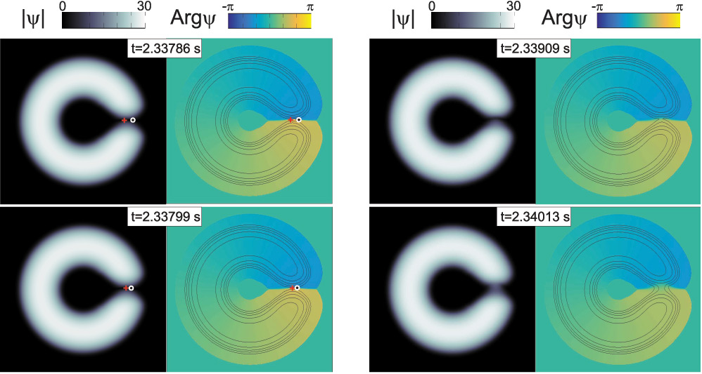
This hypothesis is supported by investigations of the dynamics of the phase of the order parameter and by analysis of the vortex core position during the phase slip. Typical examples of phase-slips are shown in Fig. 2, where the white crosses indicate the positions of the vortex cores.
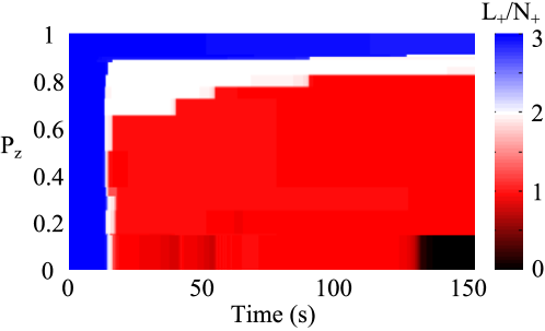
To compare our theoretical findings with the experiment Beattie et al. (2013) we present the angular momentum per particle in the major component as the function of the spin-population imbalance and time. In agreement with the experiments it is seen from Fig. 3 that above a well-defined (“critical”) value for the persistent current is stable. Below this critical value the supercurrent decays rapidly. However, the experimentally observed “critical” value () is well below our predictions (). The difference between our theoretical estimates and experimental results could be minimized, if one properly accounts for possible deviation in the experimental conditions Moulder et al. (2012) of 3D distribution of the trapping potential from the pure Laguerre-Gauss shape assumed in our 2D model. A more accurate description of the dissipative processes could also improve the quantitative agreement with the experiment. Indeed, the phenomenological parameter , which describes the dissipation in our simulations, is in general temperature- and position-dependent, which is not included in our simple model.
III Generation of the persistent current in a stirred toroidal BEC
III.1 Persistent current generation by a small stirrer
Very recently Wright et al. (2013), vortices in a toroidal trap were excited using a small (diameter less than the width of the annulus) variable-height potential barrier (a “stirrer”) with an angular velocity ranging from zero up to the speed of sound in the condensate. A wide range of the experimental parameters used in Ref. Wright et al. (2013) opens an intriguing possibility for theoretical investigation of excitation of the persistent current in a stirred ring-shaped BEC at different regimes. As in case of decay of persistent flow, in modeling of nucleation of vortices dissipative effects are of crucial importance since they provide the mechanism for damping of elementary excitations in the process of relaxation to an equilibrium state. It is the dissipation that either causes the vortex line to drift to the outer edge of the condensate (where vortices decay) or leads to the pinning of the vortex in the central hole of the ring-shaped condensate. The relaxation of the vortex core position to the local minimum of the energy leads to formation of the metastable persistent current.
The trapping potential
consists of an axially-symmetric time-independent toroidal trap:
| (7) |
where , and the repulsive potential of optical blue-detuned stirring beam:
| (8) |
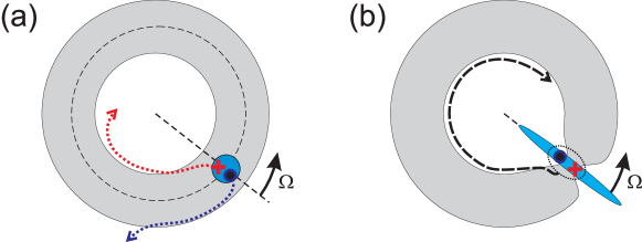
where is the coordinate of the barrier center, moving counter-clockwise with a constant angular velocity through the maximum of condensate density [see Fig. 4 (a)]. According to experimental parameters the effective width of the beam is less than the width of the annulus , but is ten times greater than the healing length . The function describes the temporal changes in the barrier height: linearly ramps up in the first s of evolution from zero to and remains unchanged for s, then in the last s it ramps down to zero again.
Similarly to how it was done for GPE for spinor condensates [see Eq. (4)] one can obtain a dissipative dimensionless GPE in 2D:
| (9) |
where and are the dimensionless potential and the radius of the trap, is the dimensionless 2D interaction constant, is dimensionless wave-function. Here we use harmonic oscillator units: , , , .
In Ref. Yakimenko et al. (2014) we have observed two regimes of the vortex excitation in a toroidal BEC. For a low angular velocity of the stirrer vortex-antivortex pair is nucleated near the center of the barrier (see Fig. 4 (a)). Then the pair undergoes a breakdown and the antivortex moves spirally to the external surface of the condensate and finally decays into elementary excitations, while the vortex becomes pinned in the central hole of the annulus adding a unit to the topological charge of the persistent current. The progressive drift of the vortices towards the external condensate boundary is the result of dissipation, which leads to the vortex energy decay. Described behavior is characteristic for low intensities. In contrast, if is much higher than the threshold for vortex nucleation, then a wide weak link develops in a ring and breaks the potential barrier for the external vortices. As a result, a vortex from the outside of the ring can enter through the weak link. This mechanism is similar to stirring with a wide barrier observed in Ref. Wright et al. (2013) and described theoretically in Ref. Yakimenko et al. (2014).
For higher angular velocities of the stirrer the dominating source of vortices is the instability of the external surface modes. First, ripples appear at the external surface, and then several vortices nucleate simultaneously. It is remarkable that Bogoliubov analysis gives practically the same above which such surface modes are exited. Also, similar to the case of high barrier intensities , vortex lines come into the bulk of the condensate through the rotating weak link. Further complex dynamics of the vortices is governed not only by the condensate inhomogeneity and dissipation effects, but also by the interplay between condensate flows corresponding to other vortices. The number of vortices increases dramatically in our simulations with increasing barrier amplitude , so that dynamics of the vortices becomes quite irregular.
As is well known (see, e.g. Tsubota et al. (2013)), small-scale forcing may generate large-scale flows in effectively 2D turbulent classical and quantum fluids. The energy of small-scale forcing transits first to irregular vortex distributions and then relaxes to a large-scale flow in a form of a circulating superflow. For example, as is shown in Ref. Yakimenko et al. (2014), the number of vortices and antivortices rapidly increases when the stirring beam ramps up, and decays to zero when the stirring beam is switched off, while the angular momentum per atom saturates to an integer number corresponding to the -charged persistent current.
It turns out that the results of Ref. Yakimenko et al. (2014) are in a good agreement with the experimentally measured Wright et al. (2013) threshold for vortex excitation especially for Hz. For the lower angular velocities the experimentally measured threshold value of the barrier height is well below the predictions of our 2D model, as well as of the 1D model suggested in Ref. Wright et al. (2013).
III.2 Quantum vortices driven by a rotating weak link
In the present subsection we briefly overview our recent investigation Yakimenko et al. (2014) of the formation of persistent currents by a wide rotating barrier, i.e. the barrier that is wider than the ring [see Fig. 4 (b)]. The rotating barrier dynamically modifies the condensate density. Then it not only creates a weak link, but also induces superflows in the ring-shaped condensate. We have analyzed in Ref. Yakimenko et al. (2014) the influence of both these factors on the energetic and dynamical stability of the vortices in the toroidal condensate.
In the mean field approximation, the dynamics of a system of weakly interacting degenerate atoms close to thermodynamic equilibrium and subject to weak dissipation is described by the following dimensionless 3D GPE Pitaevskii (1959); Choi et al. (1998):
| (10) |
The external potential consists of the axially-symmetric, time-independent toroidal trap (7) and the time-dependent potential of a rotating repulsive barrier . The rotating barrier is experimentally created by a blue-detuned laser beam scanning across the condensate in radial direction, with a scan amplitude greater than the width of the annulus Wright et al. (2013). For simplicity, we have assumed the resulting averaged potential to be homogeneous in radial direction across the toroidal condensate,
| (11) |
where is the radius-vector in plane and the unit vector points along the azimuth of the barrier maximum. The Heaviside theta function in Eq. (11) assures a semi-infinite radial barrier potential starting at the trap axis. All parameters of the problem were chosen to match the experimental conditions in Wright et al. (2013) (see Ref. Yakimenko et al. (2014) for details).
Following the experimental setup Wright et al. (2013) we first prepare a nonrotating state in the toroidal trap. We use the imaginary time-propagation method to find numerically the stationary solution of the Eq. (10) without the weak link () and without dissipation (). In the experimental procedure the amplitude of the weak link varies in time: the height of the potential barrier ramps up to a maximum value during the first 0.5 s. For the next 0.5 s the amplitude of the barrier remains constant, and then, the potential barrier ramps down again within 0.5 s. During all the 1.5 s of stirring time the barrier moves anti-clockwise with constant angular velocity . In the experiment Wright et al. (2013) the values of angular velocity were taken in the range Hz, that correspond to linear velocities well below the speed of sound propagating around the ring. For slow rotation rates pronounced quantized phase slips were observed at well-defined critical angular velocities. In Ref. Yakimenko et al. (2014) we have numerically simulated the generation of persistent currents via such phase slips driven by a wide rotating barrier using parameters adjusted to the experimental conditions in Ref. Wright et al. (2013).
Let us discuss the mechanism of these phase slips. During the stirring procedure two vortices of opposite charges are nucleated on inner and outer edges of the weak link (see Fig. 5). As the superflow velocity is bigger on the outer edge, the vortex from outside enters the weak link first and travels towards the central hole as illustrated in Fig. 4 (b). While the vortex traverses the weak link, a negatively-charged anti-vortex line from the central hole and the incoming vortex approach each other and create a vortex-antivortex dipole. This coupled pair of vortices circles clockwise inside the central hole until it reaches the region of the weak link. The moving dipole usually escapes from the central hole and finally decays, however, during the stirring time the vortex dipole can enter and leave several times the central hole of the ring through the weak link.
If the barrier rotation rate is well above a threshold, usually several vortices enter into the central hole and form bound pairs with anti-vortices from the central hole. Finally the vortex-antivortex pairs jump out of the condensate. The total angular momentum of the escaping vortex dipole is equal to zero, but each time an external vortex enters the condensate it adds one unit of topological charge to the global persistent current.
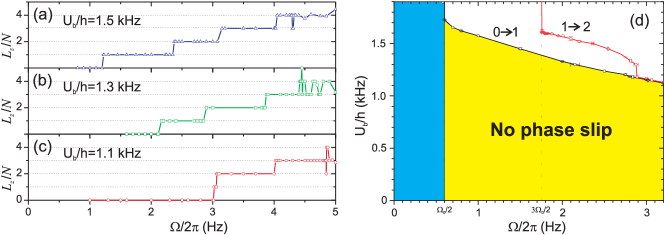
For higher angular velocities some integer-valued fluctuations appear in as the function of . When grows further the angular momentum increases on average, however the specific value of at s becomes quite unpredictable. Surprisingly, even substantial increase of the evolution time to 4.5 s does not remove all the fluctuations. The reason is that the interaction between flows of annular vortices together with moving barrier leads to a quite complicated dynamics which can not be considered as a deterministic phase slips any more.
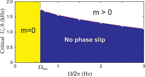
We have performed in Ref. Yakimenko et al. (2014) a series of numerical simulations for various combinations of and . To summarize our finding, we present in Fig. 6 the threshold for phase slip in the plane of the weak link parameters: barrier height and . The critical barrier height for each shown in Fig. 6 was obtained with accuracy not worse than 5 Hz. In qualitative agreement with the experiment, the threshold barrier height increases when the angular velocity decreases. Particularly striking is that below a well-defined angular velocity Hz the phase slip does not occur at any barrier height . The value of minimal angular velocity appears to be close to predictions of Ref. Eckel et al. (2014): , where Hz is the rotational quantum. As it will be shown in the Sec. IV, formation of the persistent currents becomes energetically unfavorable for .
For even higher angular velocities of the rotating barrier the persistent current generation mechanism is quite different from the slow–rotation case and governed by the excitation of external surface modes, similarly to what was observed in Ref. Yakimenko et al. (2014). Worth noticing here that highly-charged persistent currents, which are generated by the rapidly-rotating barrier can be unstable with respect to serial emission of vortex lines. During such an emission process a vortex line spirals out from the central hole of the toroid through the bulk of the condensate without weak link.
Our theoretical results are in qualitative agreement with the experimental findings: the threshold angular velocity decreases when the barrier height increases. However, comparison of the two experimental series for the fixed barrier height with Fig. 6 shows that the theoretically predicted is higher than the experimentally measured angular velocity for the phase slip .
IV Hysteresis in a superfluid ring
Hysteresis is widely used in electronics and it is routinely observed in superconducting circuits. Controlled hysteresis in atomtronic circuits may prove to be a crucial feature for the development of practical devices, as it has proved in electronics, e.g. in memory cells, digital noise filters and magnetometers. Very recently Eckel et al. (2014) the hysteresis between quantized circulation states in a ring-shaped condensate with a rotating weak link has been experimentally demonstrated. It was proved, that generation of the persistent current becomes possible at angular velocity of the repulsive barrier, but the decay of the persistent current corresponds to lower rotation rate . The experimental results of Ref. Eckel et al. (2014) suggest that relevant excitations involved in the observed processes are vortices, and indicate that gain and dissipation of the energy has an important role in the dynamics in this open-dissipative quantum system. However, the details of the process of abrupt change of the rotation state driven by a tunable rotating weak link are not elucidated yet. Furthermore, a challenging issue is that the width of a hysteresis loop , obtained in the framework of commonly used version of the dissipative GPE, appears to be substantially overestimated in comparison with the experimental measurements. It was assumed in Ref. Eckel et al. (2014) that an agreement with the experiment will be reached in the framework of more sophisticated models that allow for changes in chemical potential and atom number. To describe the hysteresis process we use here the generalized 2D dissipative GPE with time-dependent chemical potential, which accounts on a decay of the number of atoms with time.
In the present section we use a 2D analogue of the 3D model described in Sec. III.2. As pointed out above, the BEC cloud is highly anisotropic in the experimental setup, thus the 2D model is supposed to properly describe the main features of the vortex dynamics. The first task of this section is to establish the parameters of the 2D model, which gives a good quantative agreement between the details of dynamics of the vortex excitations observed in the 3D model and in the reduced 2D approximation. Having this goal in mind we use the parameters of the experiment Wright et al. (2013) and compare our findings concerning generation of the persistent current with the results of the more general 3D model, described in Sec. III.2. We note that the problem of the dimensionality reduction in context of ring-shaped BEC has been discussed in the literature (see, e.g. Salasnich et al. (2007); Morizot et al. (2006)), however, to the best of our knowledge, the direct comparison of the dynamics of the vortices in 3D toroidal condensate and reduced 2D annular model was not performed yet. For further chemical potential of the 2D model is related to 3D chemical potential as follows: . Such relation is prescribed by the factorization of the -coordinate (4) and is nothing but the energy of the ground state in the oscillator potential. In dimensionless units the parameters of 2D model are as follows: , , . Our results obtained in the framework of (2+1)D dissipative GPE are in very good agreement with the 3D results (compare Figs. 7 (d) with 6). For slow rotation rate the vortices forme a dipole, which escapes from the condensate in a similar way as it happens in 3D model Yakimenko et al. (2014). At relatively rapidly rotating barrier, the dependence of the angular momentum per atom becomes irregular (see Fig. 7) and it becomes difficult to find a threshold for a phase slip with . As is seen from Fig. 7 (c), (d), for higher rotation rate the thresholds for the phase slips and merge. It is noteworthy that the higher order phase slips for occur in our numerical simulation only above a well defined angular velocity of the weak link: .
Having established a quantitative agreement between 3D and 2D models for the generation of the persistent current we considered the inverse process, a decay of the superflow in the ring-shaped BEC by the rotating weak link. Further we restrict our consideration to the first phase slip , when the single-charged persistent current is generated, and inverse process of persistent current decay, corresponding to the phase slip . Also we concentrate on the case of slow rotation rate when the barrier height is just above a threshold value for vortex generation (see Fig. 7 (d) and Fig. 6). We use a state with , which is formed by the 1.5 s stirring process with parameters , as an initial condition for a series of simulations of another 1.5 s stirring process with the same barrier height and different values of angular velocity . Some typical examples of the dynamics of the persistent current decay are given in Figs. 8, 9
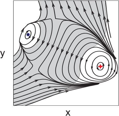
Let us discuss the microscopic mechanism of the persistent current generation and decay in more details. It was pointed out in Ref. Eckel et al. (2014), that both generation and decay of the persistent current in a stirred ring-shaped condensate are associated with dynamics of the excitations in the form of the vortex dipoles, which is a generic feature of a superfluidity in a quasi-two-dimensional geometry. We find out that the phase slips observed in our numerical simulations are generally accompanied by formation of a moving vortex dipole. As was illustrated in the Sec. III.2 (see Fig. 5) for the case of the phase slip the azimuthal velocity of the superflow is positive (forward flow) far from the weak link, but inside the weak link (backward flow). The rotating weak link induces the backward component of the superflow also during the inverse phase slip . When the vortex and antivortex form a bounded pair inside the rotating weak, the linear momentum of the backward flow can be transferred into the momentum of the dipole. The attraction between the oppositely charged vortex lines can be balanced by the Magnus force, which is induced by the superflow of the moving vortex dipole. As the result the vortex dipole moves with linear velocity , where is the dipole size (distance between the cores of vortex and antivortex), is the healing length.
As it is known (see, e.g. Tempere et al. (2014)), the vorticity energy of the vortex dipole in an inhomogeneous condensate decays both for large dipoles (when is of order of the condensate size so that the vortex cores appear at the low-density region) and for small dipole sizes (when is of order of the vortex core radius ). Therefore, the contribution to the condensate energy of a vortex-antivortex pair as a function of dipole size must have a maximum, which defines the dissociation size of the dipole: . Formation of the vortex dipole can be described as follows: When the barrier height grows, the width of the condensate in the weak link decreases so the distance between vortex and antivortex from the internal and external side of the annulus decreases. For a compact vortex-antivortex pair with formation of the bound state in the form of vortex dipole becomes energetically preferable.
As was pointed out above, the moving dipole can be supported against 2D reconnection (collapse) by the Magnus force. However, if the rotation rate of the weak link is very low, the vortex dipole, emerging during phase, slip is too slow to form a stable bound state. In this case the collapse inside the weak link is observed (see Fig. 8), which is consistent with previous theoretical findings Piazza et al. (2009, 2013) concerning persistent current decay in a toroidal condensate with a non-rotating tunable weak link.
Therefore during the phase slip the linear momentum of the backward flow, induced by rotating weak link, is picked up by the moving dipole. Further evolution of the moving dipole can be accompanied by different processes: by dipole dissociation; by topological charge exchange of the moving dipole with the ”ghost vortices” at the periphery of the condensate; by reversible transformation of the dipole into a gray soliton Prabhakar et al. (2013); Kwon et al. (2014) or by annihilation of the dipole with sound pulse emission. Illustration of some of these processes is given in Fig. 9, however the detailed description of the complex dynamics of the vortices in the stirred toroidal condensate is beyond the scope of the present work.
The remarkable feature associated with generation and decay of the persistent current is the hysteresis effect Eckel et al. (2014). Hysteresis is a general property of systems where the energy has multiple local minima separated by an energy barrier. For a Bose–Einstein condensate (BEC) in a ring-shaped trap, these minima represent stable flow states of the system, and their energies depend on the applied rotation rate of the trap and the amplitude of a rotating repulsive perturbation (weak link), which induces the rotation.
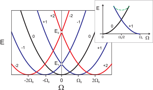
As known (see, e.g. Baharian and Baym (2013); Mueller (2002)) the noninteracting single-particle energy levels, shown in Fig. 10, are periodic functions of with period . The single-particle spectrum in a 1D ring of radius can be described in the rotating frame as follows: where is the characteristic scale of rotation in the system. With the addition of interactions, an energy barrier appears, separating -charged metastable flow states (see the inset in Fig. 10). This barrier stabilizes the flow, making the persistent current very long-lived.
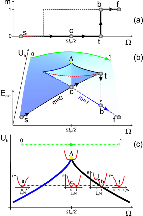
To gain a better insight into the properties of the generation and decay of the persistent current it is useful to consider an energy landscape of a rotating superfluid ring. The energy of the condensate as a function of the angular momentum per particle are sketched in Figs. 11 (c) for different values of . It turns out that for some range of control parameters and the energy landscape exhibits two local minima at integer (here we consider and states). The values of the energy at minima for different values of and form a self-intersecting surface, which is shown schematically in Fig. 11 (b). Obviously, the presence of two local minima at a given value of control parameter assures that there is a maximum separating them. The barrier state (energy of the maximum) is also shown in Fig. 11 (b) forming the top of the “swallow tail”. The slice of the surface at fixed in Fig. 11 (b) represents the energy of the maximum by dash-dotted red line, and the energy at () minimum by dashed black (blue) line (see also the inset in Fig. 10). At the point labeled by in Fig. 11, one of the local minima (with ) meets up with the maximum, and they both disappear. The points where the maximum of the energy merges with the minimum at () form the solid black (blue) line. The projections of these lines onto the plane are shown in Fig. 11 (c) and Fig. 12. The region with three extrema of the energy landscape is bounded from above by these curves. The “swallow-tail” energy spectrum is associated with a cusp catastrophe with a typical for such catastrophe half-cubic line of the catastrophe:
| (12) |
where is the coordinate of the cusp point indicated in Fig. 11 (b),(c) and is a constant. As was pointed out above, the energy spectrum of the condensate in the ring is a periodical function of the angular velocity with period , where is the quantum of rotation. From the symmetry of the energy spectrum it follows, that the energy spectrum branches for and cross at . Thus, the cusp point in catastrophe set corresponds to . It is remarkable that the function (12) fits the threshold for transition surprisingly well (see Fig. 12 and Fig. 6).
A “swallow-tail” structure of the energetic spectrum results in a hysteretic response of nonlinear system to variations of a control parameter. The transitions and occur at different values of and form a hysteresis loops illustrated in Fig. 11 (a). The hysteresis exists for that region of , where there are three extrema of the energy landscape. It is instructive to consider the response of the system on the variation of the angular velocity of the weak link at fixed barrier amplitude. Let us describe an example of the generation of the persistent current. We start at a ground state (point in Fig. 11), when there is only one energy minimum at . When grows we cross the blue cusp curve and the second local minimum at appears. The energy of two local minima become equal at (point ). At the point labeled by in Fig. 11, the local minima at disappear and the system jumps to the state with a minimum at . This abrupt transition corresponds to the phase slip shown in Fig. 11 (a). The local maximum of the energy corresponds to an unstable solution, which is associated with the vortex excitations. If grows even further, the local minimum at also disappears and phase slip is observed.
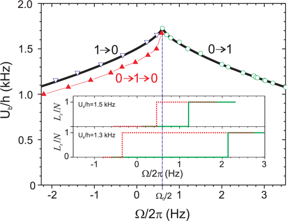
The Figure 12 summarizes our findings concerning the boundaries of the regions with the phase slip: open green circles give the boundary for the phase slips [shown also in Fig. 7 (d)], filled red triangles represent the edge of the region with phase slips. The filled red triangles correspond to the two-stage stirring procedure : the persistent current is generated during 1.5 s of the first stirring stage, the persistent current decay via phase slip during next 1.5 s.
Consideration of the energy landscape of the conservative system suggests the symmetry of the hysteresis loop with respect to the frequency [see Fig. 11 (a)]. In a sharp contrast to these expectations a considerable asymmetry of the hysteresis loop, obtained by direct numerical simulations of the dissipative dynamics of the condensate, is clearly seen in the numerically obtained hysteresis loops (see the inset in Fig. 12). Note that the lifetime of the condensate is specified to be 10 s, that results in a decay of about a quarter of the initial number of atoms during the 3 seconds of simulation time. Thus, the asymmetry of the hysteresis loop in this case can be explained by a considerable asymmetry in the initial values of the number of atoms for the forward () and backward () branches of the hysteresis loop.
In support of this conjecture we have verified, that the hysteresis loop becomes symmetric providing the same duration of the stirring procedure and equal values of the total number of atoms in the initial state for generation of persistent current via the phase slip and for decay of the persistent current via phase slips. The open blue triangles in the Fig. 12 correspond to the threshold of the phase slip, when the stationary solution of the GPE with was used as initial condition for the stirring procedure duration of 1.5 s.
It is remarkable, that the experimental hysteresis loops Eckel et al. (2014) are symmetric with respect to . The point is that to observe a symmetric hysteresis in the phase slips, in Ref. Eckel et al. (2014) a two-step experimental sequence was used. After condensing the atoms into the ring trap, the BEC is prepared in either the or the circulation state by either not rotating the weak link or by rotating it. The weak link was then rotated at various angular velocities, for an additional 2 s.
It was underlined in Ref. Eckel et al. (2014) that there is a large discrepancy between the models used in Eckel et al. (2014) and the experimental observations: the width of the hysteresis loop, obtained from the numerical simulations of the dissipative GPE with time-independent chemical potential (and consequently, a constant number of atoms), was much greater, then experimentally measured width of the hysteresis loop. As was pointed out above, the decay of the number of atoms leads to shrinking of the width of the hysteresis loop. Thus, it is of interest to account on this dissipative effect using time-dependent chemical potential in the framework of the stirring procedure and parameters of the experimental setup Eckel et al. (2014). As it follows from our theoretical results reported in the present paper, the correspondence between theoretical predictions and experimental observations can be radically improved, by accounting for the decay of the number of atoms with time. This work is now in progress and the results will be published elsewhere.
V Conclusions
In the present paper we overview our three recent works Yakimenko et al. (2013, 2014, 2014), which provide a theoretical description of three different experiments Beattie et al. (2013); Wright et al. (2013, 2013) with persistent current in toroidal condensate. In addition we present our new results related to hysteresis in the ring-shaped condensate, which was very recently demonstrated experimentally Eckel et al. (2014).
Existence of a long-lived persistent current corresponds to stable quantum vortex pined in the central hole of the toroidal condensate. The lifetime of this vortex line in a single-component condensate ranges up to two minutes and restricted only by the lifetime of the condensate itself. However, in the case of the two-component (spinor) BEC the stability properties of the persistent current dramatically change Beattie et al. (2013). In Ref. Yakimenko et al. (2013) we have found that phase slips occur as the result of the simultaneous action of two factors: an azimuthal symmetry-breaking instability and a dissipation effect caused by the interaction of the condensate atoms with the thermal cloud. If the number of atoms in the minor spin component becomes comparable to the number of atoms in the major component, the nonlinear repulsive intercomponent interaction leads to a separation of the spin components through an azimuthal symmetry-breaking instability. As a result of this instability, one can find regions in the condensate annulus with reduced density of one component filled by atoms of the other component. These regions serve as “gates” for the vortex lines where they readily cross the annulus, and as a consequence, the winding number of the superflow is reduced by one unit.
We have discussed our recent theoretical results concerning generation of the quantized vortices by a rotating repulsive barrier. It is remarkable that for low rotation rate both a weak link (a barrier which is wider than the condensate annulus) Wright et al. (2013) and a small (in comparison with the width of the annulus) stirrer used in Ref. Wright et al. (2013) drive the phase slip by excitation of the vortex dipoles. However, the microscopic mechanisms of the phase slip are qualitatively different for these two cases. [see Fig. 4] As was shown in Ref. Yakimenko et al. (2014), a small stirrer at low rotation rate excites vortex-antivortex pairs near the center of the rotating barrier in the bulk of the condensate. Then the pair undergoes a breakdown and the antivortex moves spirally to the external surface of the condensate and finally decays into elementary excitations, while the vortex becomes pinned in the central hole of the annulus adding one unit to the topological charge of the persistent current. For the case of the wide barrier (weak link) one observes the following: A vortex line enters the weak link from the outside and travels towards the central hole. While the vortex traverses the weak link, a negatively-charged anti-vortex line from the central hole and the incoming vortex approach each other and create a vortex-antivortex dipole. This coupled pair of vortices circles clockwise inside the central hole until it reaches the region of the weak link. The moving dipole usually escapes from the central hole and finally decays, however, during the stirring time the vortex dipole can several times enter and leave the central hole of the ring through the weak link. Though the total charge of the escaping vortex dipole is equal to zero, but each time an external vortex (or antivortex) enters the condensate it adds (or takes away) one unit of topological charge to the global persistent current.
Using the 2D dissipative GPE we have investigated a hysteresis effect of the persistent current in a toroidal BEC, driven by a rotating weak link. We have revealed that both generation and decay of the persistent current are driven by dynamics of the moving vortex dipoles. A vortex dipole emerging during the phase slip exhibits a complicated evolution, which can be accompanied by the dipole dissociation, by reversible transformation of the dipole into a gray soliton or by annihilation of the dipole with sound pulse emission. The moving dipole finally decays into elementary excitations at the boundary of atomic cloud. Our approach accounts for the decay in the total number of atoms and leads to considerable shrinking of the hysteresis loop for generation and decay of the persistent current. We believe that our results can be useful for theoretical explanation of the ongoing experiments with ’atomtronic’ circuits.
VI Acknowledgment
A.Y. acknowledges the hospitality of the Physikalisch-Technische Bundesanstalt
(PTB), where this work was commenced. S.V. is grateful to the Swiss National Science Foundation
(individual grant N IZKOZ2_154984) and to Prof. Ruth Durrer for her support and kind hospitality.
References
- Ryu et al. (2007) C. Ryu, M. F. Andersen, P. Cladé, V. Natarajan, K. Helmerson, and W. D. Phillips, Phys. Rev. Lett. 99, 260401 (2007).
- Ramanathan (2011) A. K. Ramanathan, Ph.D. thesis, University of Maryland, College Park (2011).
- Ramanathan et al. (2011) A. Ramanathan, K. C. Wright, S. R. Muniz, M. Zelan, W. T. Hill, III, C. J. Lobb, K. Helmerson, W. D. Phillips, and G. K. Campbell, Phys. Rev. Lett. 106, 130401 (2011).
- Moulder et al. (2012) S. Moulder, S. Beattie, R. P. Smith, N. Tammuz, and Z. Hadzibabic, Phys. Rev. A 86, 013629 (2012).
- Beattie et al. (2013) S. Beattie, S. Moulder, R. J. Fletcher, and Z. Hadzibabic, Phys. Rev. Lett. 110, 025301 (2013).
- Wright et al. (2013) K. C. Wright, R. B. Blakestad, C. J. Lobb, W. D. Phillips, and G. K. Campbell, Phys. Rev. Lett. 110, 025302 (2013).
- Wright et al. (2013) K. C. Wright, R. B. Blakestad, C. J. Lobb, W. D. Phillips, and G. K. Campbell, Phys. Rev. A 88, 063633 (2013).
- Ryu et al. (2013) C. Ryu, P. W. Blackburn, A. A. Blinova, and M. G. Boshier, Phys. Rev. Lett. 111, 205301 (2013).
- Neely et al. (2013) T. W. Neely, A. S. Bradley, E. C. Samson, S. J. Rooney, E. M. Wright, K. J. H. Law, R. Carretero-González, P. G. Kevrekidis, M. J. Davis, and B. P. Anderson, Phys. Rev. Lett. 111, 235301 (2013).
- Jendrzejewski et al. (2014) F. Jendrzejewski, S. Eckel, N. Murray, C. Lanier, M. Edwards, C. J. Lobb, and G. K. Campbell, Phys. Rev. Lett. 113, 045305 (2014).
- Corman et al. (2014) L. Corman, L. Chomaz, T. Bienaimé, R. Desbuquois, C. Weitenberg, S. Nascimbène, J. Dalibard, and J. Beugnon, Phys. Rev. Lett. 113, 135302 (2014).
- Ryu et al. (2014) C. Ryu, K. C. Henderson, and M. G. Boshier, New Journal of Physics 16, 013046 (2014).
- Eckel et al. (2014) S. Eckel, J. G. Lee, F. Jendrzejewski, N. Murray, C. W. Clark, C. J. Lobb, W. D. Phillips, M. Edwards, and G. K. Campbell, Nature 506, 200 (2014).
- Kasamatsu et al. (2002) K. Kasamatsu, M. Tsubota, and M. Ueda, Phys. Rev. A 66, 053606 (2002).
- Benakli et al. (1999) M. Benakli, S. Raghavan, A. Smerzi, S. Fantoni, and S. R. Shenoy, EPL (Europhysics Letters) 46, 275 (1999).
- Brand and Reinhardt (2001) J. Brand and W. P. Reinhardt, Journal of Physics B Atomic Molecular Physics 34, L113 (2001).
- Das et al. (2012) A. Das, J. Sabbatini, and W. H. Zurek, Scientific Reports 2, 352 (2012), eprint 1102.5474.
- Martikainen et al. (2001) J.-P. Martikainen, K.-A. Suominen, L. Santos, T. Schulte, and A. Sanpera, Phys. Rev. A 64, 063602 (2001).
- Modugno et al. (2006) M. Modugno, C. Tozzo, and F. Dalfovo, Phys. Rev. A 74, 061601 (2006).
- Yakimenko et al. (2013) A. I. Yakimenko, K. O. Isaieva, S. I. Vilchinskii, and M. Weyrauch, Phys. Rev. A 88, 051602 (2013).
- Li et al. (2012) Y. Li, W. Pang, and B. A. Malomed, Phys. Rev. A 86, 023832 (2012).
- Li et al. (2014) Y. Li, W. Pang, and B. A. Malomed, Wave Modes Trapped in Rotating Nonlinear Potentials (2014), p. 171.
- Mason and Berloff (2009) P. Mason and N. G. Berloff, Phys. Rev. A 79, 043620 (2009).
- Piazza et al. (2009) F. Piazza, L. A. Collins, and A. Smerzi, Phys. Rev. A 80, 021601 (2009).
- Piazza et al. (2013) F. Piazza, L. A. Collins, and A. Smerzi, Journal of Physics B Atomic Molecular Physics 46, 095302 (2013).
- Yakimenko et al. (2014) A. I. Yakimenko, K. O. Isaieva, S. I. Vilchinskii, and E. A. Ostrovskaya, ArXiv e-prints (2014), eprint 1408.3293.
- Yakimenko et al. (2014) A. Yakimenko, Y. Bidasyuk, M. Weyrauch, Y. Kuriatnikov, and S. Vilchinskii, arXiv preprint arXiv:1409.6260 (2014).
- Kawaguchi and Ueda (2012) Y. Kawaguchi and M. Ueda, Phys. Rep. 520, 253 (2012).
- Stamper-Kurn and Ueda (2013) D. M. Stamper-Kurn and M. Ueda, Rev. Mod. Phys. 85, 1191 (2013).
- Smyrnakis et al. (2009) J. Smyrnakis, S. Bargi, G. M. Kavoulakis, M. Magiropoulos, K. Kärkkäinen, and S. M. Reimann, Phys. Rev. Lett. 103, 100404 (2009).
- Smyrnakis et al. (2010) J. Smyrnakis, M. Magiropoulos, G. M. Kavoulakis, and A. D. Jackson, Phys. Rev. A 81, 063601 (2010).
- Malet et al. (2010) F. Malet, G. M. Kavoulakis, and S. M. Reimann, Phys. Rev. A 81, 013630 (2010).
- Kärkkäinen et al. (2007) K. Kärkkäinen, J. Christensson, G. Reinisch, G. M. Kavoulakis, and S. M. Reimann, Phys. Rev. A 76, 043627 (2007).
- Jackson and Kavoulakis (2006) A. D. Jackson and G. M. Kavoulakis, Phys. Rev. A 74, 065601 (2006).
- Ögren and Kavoulakis (2007) M. Ögren and G. M. Kavoulakis, Journal of Low Temperature Physics 149, 176 (2007).
- Brtka et al. (2010) M. Brtka, A. Gammal, and B. A. Malomed, Phys. Rev. A 82, 053610 (2010).
- Anoshkin et al. (2013) K. Anoshkin, Z. Wu, and E. Zaremba, Phys. Rev. A 88, 013609 (2013).
- Bargi et al. (2010) S. Bargi, F. Malet, G. M. Kavoulakis, and S. M. Reimann, Phys. Rev. A 82, 043631 (2010).
- Świsłocki and Matuszewski (2012) T. Świsłocki and M. Matuszewski, Phys. Rev. A 85, 023601 (2012).
- Choi et al. (1998) S. Choi, S. A. Morgan, and K. Burnett, Phys. Rev. A 57, 4057 (1998).
- Pitaevskii (1959) L. Pitaevskii, Sov. Phys. JETP 8, 88 (1959).
- Tsubota et al. (2013) M. Tsubota, M. Kobayashi, and H. Takeuchi, physrep 522, 191 (2013).
- Salasnich et al. (2007) L. Salasnich, B. A. Malomed, and F. Toigo, Phys. Rev. A 76, 063614 (2007).
- Morizot et al. (2006) O. Morizot, Y. Colombe, V. Lorent, H. Perrin, and B. M. Garraway, Phys. Rev. A 74, 023617 (2006).
- Tempere et al. (2014) J. Tempere, S. Driezen, W. V. Alphen, E. Lories, and E. Vermeyen, Journal of Low Temperature Physics 175, 189 (2014).
- Prabhakar et al. (2013) S. Prabhakar, R. P. Singh, S. Gautam, and D. Angom, Journal of Physics B Atomic Molecular Physics 46, 125302 (2013).
- Kwon et al. (2014) W. J. Kwon, G. Moon, J.-y. Choi, S. W. Seo, and Y.-i. Shin, ArXiv e-prints (2014), eprint 1403.4658.
- Baharian and Baym (2013) S. Baharian and G. Baym, Phys. Rev. A 87, 013619 (2013).
- Mueller (2002) E. J. Mueller, Phys. Rev. A 66, 063603 (2002).