Optimization of the geometrical stability in square ring laser gyroscopes
Abstract
Ultra sensitive ring laser gyroscopes are regarded as potential detectors of the general relativistic frame-dragging effect due to the rotation of the Earth: the project name is GINGER (Gyroscopes IN GEneral Relativity), a ground-based triaxial array of ring lasers aiming at measuring the Earth rotation rate with an accuracy of rad/s. Such ambitious goal is now within reach as large area ring lasers are very close to the necessary sensitivity and stability. However, demanding constraints on the geometrical stability of the laser optical path inside the ring cavity are required. Thus we have started a detailed study of the geometry of an optical cavity, in order to find a control strategy for its geometry which could meet the specifications of the GINGER project. As the cavity perimeter has a stationary point for the square configuration, we identify a set of transformations on the mirror positions which allows us to adjust the laser beam steering to the shape of a square. We show that the geometrical stability of a square cavity strongly increases by implementing a suitable system to measure the mirror distances, and that the geometry stabilization can be achieved by measuring the absolute lengths of the two diagonals and the perimeter of the ring.
1 Introduction
A ring laser (RL) gyroscope is composed by a square or triangular optical cavity inside which two opposite light beams propagate in a closed loop. In a reference frame rotating at velocity with respect to an inertial frame, the opposite directions are not equivalent; the two laser emission frequencies are then splitted by the Sagnac frequency :
| (1) |
where is the oriented scale factor, is the vectorial area enclosed by the laser beams, is the optical wavelength and the length of the round-trip path. The frequency difference can be measured by observing the beat note between the two counter-propagating beams.
The fundamental limit to the angular velocity resolution of a RL is given by the photon shot-noise. The power spectral density of shot noise, converted in equivalent rotational noise and expressed in unit of , reads [1]
| (2) |
where is the quality factor of the optical cavity, the Planck constant, the optical power detected by photodiode, the measuring time, the speed of light, and the light frequency.
Significant advancements in RL sensitivity have recently driven new applications concerning Geophysics, Geodesy and test of General Relativity [2, 3, 4, 5]. A present challenge of this research is the observation of the relativistic Lense-Thirring effect, a perturbation of few parts in to the Earth rotation rate. Such a measurement requires a calibration of the RL with respect to the local spacetime, in order to measure the Earth rotation with high accuracy. On the other hand, the time dependent fluctuation of scale factor, backscattering and laser dynamics induced non-reciprocal effects have to be controlled in order to fully exploit the RL sensitivity up to the shot noise level in equation 2. In recent papers [7, 8] we addressed the role of laser dynamics on the stability and accuracy of a ring laser used as rotation sensor; in this work we focus on the role of cavity deformations on and .
The design of the cavity is crucial for the stability of the geometrical scale factor . The most stable and sensitive rotation sensor at present, the Gross Ring G (Wettzell, Bavaria) [6], has an optical cavity with a side length of 4 m, and has been constructed on a rigid frame made of . In this case the geometrical stability is obtained by fixing the mirrors to a very rigid and heavy structure, and by minimizing thermal expansions and pressure variations. This experimental set-up has shown that ring lasers have the potentiality to measure the Lense-Thirring effect on an Earth based experiment, but the ’monolithic’ design cannot be extended to a triaxial array of ring laser with sides of , as required by the GINGER project [5]. An heterolithic design must be considered: the cavity frame can be made of more standard materials with thermal expansion coefficients at the level of several ppm/K, and the mirror positions must be actively controlled in order to compensate the frame deformations by implementing a suitable system to measure the mirror distances based on ultra-stable optical frequency references.
A detailed study of the effects of geometrical distortions on the
optical path is the first necessary step toward the active control of mirror positions.
In the literature, one can find many papers about the geometry of a ring cavity [9, 10, 11, 12, 13, 14, 15].
In this paper we adress for the first time the problem to find a suitable approach to minimize the scale factor variations, and pose the basis for the control of an heterolithic ring laser cavity. Our study is based on Fermat’s principle to model the optical cavity geometry
starting from the position of the center of curvature of the mirrors.
We demonstrate that in a square cavity the control of the length of the two diagonals plays an important role. In fact, if the two RL diagonals are locked to the same absolute length, the optical cavity length has a stationary point corresponding to the regular square cavity, with two important implications for the control of an heterolithic structure: i) one can implement a procedure to approach the regular geometry; ii) in this case, the residual deformations contribute with quadratic terms depending on the ratio between the cavity side-length and the mirrors radius of curvature.
The paper is organized as follows. In section 2 we used the Fermat’s
principle to calculate the light path inside a closed optical cavity formed
by four equal spherical mirrors. Section 3 is devoted to the decomposition of the
cavity deformations in a suitable eigenvectors basis and to the estimation of their contributions
to the cavity perimeter and scale factor.
Section 4 reports the analysis of the perimeter and scale factor variations
due to the residual deformations in a square cavity with fixed diagonal lengths;
conclusions are drawn in section 5.
2 The geometrical model of the optical cavity
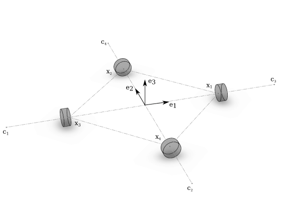
We consider a square ring optical cavity defined by four spherical mirrors. Let and denote the radius and the center of curvature of the mirror with . The four light spots can be usefully represented as the elements of , i.e. points on the spheres representing the mirrors; let be the position vector of the spot with respect to a reference frame, and the directional cosines of the spot position with respect to its mirror center. We introduce the compact notation for the directional cosine matrix , the mirror configuration matrix , and the curvature radii matrix . In this notation the spot position matrix can be written as .
Our aim is derive a functional dependence between the spot position matrix and the mirror configuration matrix . Since each mirror displacement can be described as a variation of the position of its curvature center, the four vectors represent a set of dynamical variables of the system. All the relevant quantities, with respect to the Sagnac signal and its noise, will be given in terms of these variables. The 4 geometrical constraints , ( are points of spherical surfaces), reduce the dimensions of the set of from dim to dim.
The Euclidean distances among the pairs of the four light spots are given by
| (3) | |||||
where is the Euclidean norm in . The optical path length is simply the sum of the lengths of the sides of the, in general non-planar, optical cavity
and the modulus of the enclosed area reads
| (4) | |||||
where is the angle between the vectors
and . If the 4 mirror centers
lie in the same plane these vectors represent the diagonals of a polygon.
In this case ,
and coincide with the perimeter
and diagonal lengths of the corresponding planar polygon.
The effective directional cosine matrix for a given mirrors configuration and curvature radii is found by using the Fermat’s principle [16] which states that light rays follow extremal optical paths, i.e.
| (5) |
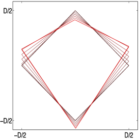
where is the gradient with respect to a coordinate set of . The vector components are referred to a clockwise orthonormal coordinate system with the origin in the center of the square, the axes and along the two diagonals, and perpendicular to the square (see figure 1).
In this coordinate system, the ideal mirrors configuration for the regular square cavity, with side length and all the mirror curvature radii equal to , is represented by the matrix
Then the matrix
is the solution of equations 5 for the spot directional cosines. In general, equations 5 are
an irrational algebraic system
of equations, and no analytic solution is available. However, for small deformations,
we can calculate the Taylor expansion of in a neighborhood of .
Let us consider the matrix . The columns of parametrize the tangent vectors to , i.e. each columns of , identified as a vector of , is orthogonal to the corresponding column of :
We obtain the new point of using the map , column-wise on , so that each column of is the corresponding column of normalized. The matrix can be considered as a function of the vector , and therefore can be also regarded as a function of . A second order geometric model of the function is then
| (6) |
where the vector and the matrix are the gradient and Hessian of the function with respect to , respectively.
Thus substituting equation 6 in equations 5 we find that the stationary point for this geometric model is given by
| (7) |
The corresponding extremal optical length is
and the new spot positions are .
The matrix has a straightforward interpretation as
the ray matrix of the RL cavity, while the vector can
be interpreted as the linear response of the optical cavity to a displacement
of the centers of curvature from the ideal mirrors configuration.
3 The eigenvectors basis of the cavity deformations
The geometry of the cavity is uniquely determined by the mirror configuration matrix , representing the position of the centers of curvature of the four mirrors. Consider a generic curve in , starting at . To classify the cavity deformation we differentiate with respect to , and then express the components of the columns of with respect to a suitable basis of the tangent space in
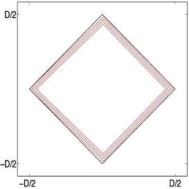
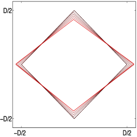
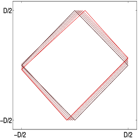
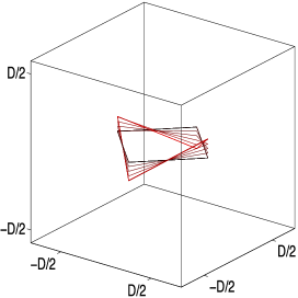
where is the element of the basis of the matrices, and . With reference to the polygon defined by the position of the centers of curvature of the four mirrors, the basis elements can be classified depending on their effects on the geometry of the optical cavity (see figure 2) as follows:
-
•
common and differential stretching of the diagonals
-
•
shear planar deformations
-
•
diagonal tilts and out of plane motions
-
•
rigid body translations
-
•
infinitesimal rigid body rotations
 ,
,
 ,
,
 ,
,
By definition, the six distances and their functions, such as and , do not depend, to the first order in , on the rigid body translation and rotations represented by the with . Therefore the mirror configuration matrix for a general deformation of the cavity is given by
The expansion of in power series of the , retaining only second order terms, reads
| (8) |
depends linearly on the diagonal common stretching, while it depends quadratically on differential stretching, shears and tilts. Assuming that the cavity satisfies the stability condition for the confinement of the optical rays [17], the coefficients of , and are negative.
Combining equation 8 and equation 4, and assuming the cavity oriented along the direction of maximum rotational signal (), the ring laser scale factor reads
| (9) | |||||
From equation 8 and equation 9 we note that, to obtain an accuracy of 1 part in on , the relative amplitude of deformation has to be , while the requirements on the other cavity deformation amplitudes are drastically reduced by the quadratic dependence.
4 Discussion
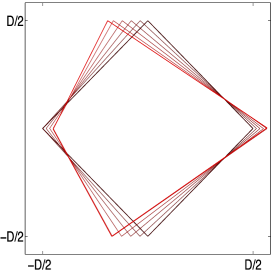
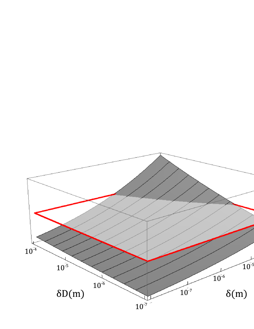
The measurement of the length of the two diagonals provides a very precise observable to constrain the deformation [18]. The model has shown that the stabilization of the length of the two Fabry-Pérot resonators, and consequently of the distance between the centers of curvature of the diagonally opposite mirrors, provides a high rejection of the mirror perturbations even if their values are biased by some systematic errors. In figure 3 we report the results of a simulation where the position of each corner mirror is varied randomly in the three directions of space with a standard deviation under the constraint of equal diagonals. The relative variation of the scale factor is plotted for different values of the unbalance between the two diagonal absolute lengths. Note that even in the case of a systematic error in the difference between the two diagonal cavities lengths of [18], the scale factor stability is compliant with the requirements of GINGER ().
The results of equation 8 and equation 9 provide a procedure in order to approach the regular square geometry, starting from a generic mirror configuration. Let us consider the distances and between the centers of curvature of the two pairs of opposite mirrors; imposing that the two diagonals have equal distance , i.e.
we have that and .
The radius of curvature plays also an important role: if we define , the expressions for the constrained perimeter and
scale factor, normalized with respect to their nominal values of the square and , can be rewritten as:
| (11) |
and
| (12) | |||||
| , |
where .
Now and are quadratic
forms of with no cross terms and the regular square geometry
corresponds to a saddle-point of . It has been already pointed out the importance
to operate the ring with a geometry as close as possible to a square, which for a large apparatus cannot be obtained by construction.
The presence of a saddle-point means that an experimental procedure to approach the square configuration, by monitoring the perimeter length, exists; this can be made with very high accuracy through the measurement of the laser emission frequency. The present analysis shows as well that the spot of the beams on the mirrors should be in the ideal position with tolerances of microns.
It is straightforward to see that the coefficients of the have a very similar behaviour in both equations; in particular they are constant and equal to , for ; while the others depend on . The ideal condition should be to work with a value so that the coefficients of are large in equation 17 (which means that we can approach more accurately the regular geometry) while the corresponding coefficients in equation 18 are small (which means that the rotational sensitivity is less affected by the geometry nonregularities). By these considerations, large radius of
curvature seams offer the best compromise. Values of around must be avoided; actually, for the cavity becomes instable, being confocal in the sagittal plane [14].
The design of the RL optical cavity should be made considering as well the features of the resulting Gaussian beam, taking also into account the active medium inside the cavity. In particular, the beam radius in the waist is very interested in, since the gain medium is usually located in it, and the optimal waist radius should be selected to be a tradeoff between low losses (small beam radius) and high output power (large beam radius). In this respect the model is not complete. The authors intend to make a more detailed analysis in a subsequent work.
5 Conclusions
We presented a suitable formalism based on the Fermat’s principle of optics to define the beam path geometry in a square cavity RL. This allows us to identify the rigid body motion of the cavity and then to classify the residual optical cavity deformations . We demonstrated that when the configuration of the mirrors is close to that of the regular square cavity, the scale factor and the perimeter length of a RL depend linearly only on the cavity isotropic expansion . It follows that, once the diagonal lengths are set to the same value, the effects of the remaining deformations on the RL scale factor are quadratic in their amplitudes . This observation is at the basis of a possible saddle-point optimization of the different deformations ; keeping the mirror positions within few m, the stability of part in in the RL scale factor can be obtained. The important conclusion is that an heterolithic structure can be utilized for high sensitivity and stability RL.
Acknowledgements
We thank A. Saccon for usefull discussions on matrix manifold theory.
One of us (D.C.) also thanks the Eindhoven University of Technology, Netherlands, for the kind hospitality.
Finally, the authors thank G. Cella for his constructive suggestions.
References
References
- [1] Stedman G E 1997, Ring laser tests of fundamental physics and geophysics, Rep. Progr. Phys. 60, 615-688
- [2] Schreiber K U and Wells J-P R 2013, Invited Review Article: Large ring lasers for rotation sensing, Rev. Sci. Instrum 84, 041101
- [3] Belfi J et al 2012, Horizontal rotation signals detected by G-Pisa ring laser for the Mw=9.0, March 2011, Japan Earthquake, J. Seismology, DOI: 10.1007/s10950-0129276-9
- [4] Schreiber K U et al 2011, How to Detect the Chandler and the Annual Wobble of the Earth with a Large Ring Laser Gyroscope, Phys. Rev. Lett. 107, 173904
- [5] Bosi F et al 2011, Measuring Gravito-magnetic Effects by Multi Ring-Laser Gyroscope, Phys. Rev. D 84, 1220022
- [6] Schreiber K U et al 2009, The large Ring Laser G for Continuous Earth Rotation Monitoring, Journal of Pure and Applied Geophysics, 166 1485
- [7] Cuccato D et al 2014, Controlling the non-linear intracavity dynamics of large He- Ne laser gyroscopes, Metrologia, 51
- [8] Beghi A et al 2012, Compensation of the laser parameter fluctuations in large ring-laser gyros: a Kalman filter approach, Appl. Opt. 51
- [9] Yuan J et al 2007, Nonplanar ring resonator modes: generalized Gaussian modes, Appl. Opt. 46, 2980
- [10] Yuan J et al 2011, Generalized ray matrix for a spherical mirror reflection and its application in square ring resonators and monolithic triaxial ring resonators, Opt. Exp. 19, 6762
- [11] Lu G et al 2013, Mirrors movement-induced equivalent rotation effect in ring laser gyros, Opt. Exp. 21, 14458
- [12] Hurst R B et al 2007, An elementary proof of the geometrical dependence of the Sagnac effect, J. Opt. A: Pure and Applied Optics, 9
- [13] Currie B E, Stedman G E and Dunn W 2002, Laser stability and beam steering in a nonregular polygonal cavity, Appl. Opt, 41
- [14] Bilger H R and Stedman G E 1987, Stability of planar ring lasers with mirror misalignment, Appl. Opt. 26, 3710
- [15] Rodloff R 1987, A Laser Gyro with Optimized Resonator Geometry, IEEE Quantum Electron., 23
- [16] Born M and Wolf E 1999, Principles of Optics, Cambridge University Press, Cambridge
- [17] Saleh B E A and Teich M C 1981, Fundamentals of Photonics, John Wiley and Sons, Inc
- [18] Belfi J et al 2014, Interferometric length metrology for the dimensional control of ultra-stable Ring Laser Gyroscopes, Class. Quant. Grav. 31, 225003