4011
11institutetext: Helmholtz-Zentrum Dresden-Rossendorf,
P.O. Box 510119, D-01314 Dresden, Germany
22institutetext: Dep. of Mech. and Aerospace Engineering, Monash University,
VIC 3800, Australia
33institutetext: LIMSI-CNRS/Bâtiment 508, BP 133,
91403 Orsay cedex, France et Université
Paris-Sud, 91405 Orsay cedex, France
TOWARDS A PRECESSION DRIVEN DYNAMO EXPERIMENT
Abstract
The most ambitious project within the DREsden Sodium facility for DYNamo and thermohydraulic studies (DRESDYN) at Helmholtz-Zentrum Dresden-Rossendorf (HZDR) is the set-up of a precession-driven dynamo experiment. After discussing the scientific background and some results of water pre-experiments and numerical predictions, we focus on the numerous structural and design problems of the machine. We also outline the progress of the building’s construction, and the status of some other experiments that are planned in the framework of DRESDYN.
Introduction
Pioneered by the Riga [1] and Karlsruhe [2] liquid sodium experiments, the last fifteen years have seen significant progress in the experimental study of the dynamo effect and of related magnetic instabilities, such as the magnetorotational instability (MRI) [3, 4, 5] and the kink-type Tayler instability (TI) [6]. A milestone was the observation of magnetic field reversals in the VKS experiment [7] which has spurred renewed interest in simple models to explain the corresponding geomagnetic phenomenon [8]. This is but one example for the fact that liquid metal experiments, though never representing perfect models of specific cosmic bodies, can indeed stimulate geophysical research.
One of the pressing questions of geo- and astrophysical magnetohydrodynamics concerns the energy source of different cosmic dynamos. While thermal and/or compositional buoyancy is considered the favourite candidate, precession has long been discussed as a complementary energy source of the geodynamo [9, 10, 11, 12, 13], in particular at an early stage of Earth’s evolution, prior to the formation of the solid core. Some influence of orbital parameter variations can also be guessed from paleomagnetic measurements that show an impact of the 100 kyr Milankovic cycle of the Earth’s orbit eccentricity on the reversal statistics of the geomagnetic field [14]. Recently, precessional driving has also been discussed in connection with the generation of the lunar magnetic field [15], and with dynamos in asteroids [16].
Whilst, therefore, an experimental validation of precession driven dynamo action appears very attractive, the constructional effort and safety requirements for its realization are tremendous. In this paper, we outline the present state of the preparations of such an experiment, along with giving an overview of further liquid sodium experiments that are planned within DREsden Sodium facility for DYNamo and thermohydraulic studies (DRESDYN) at Helmholtz-Zentrum Dresden-Rossendorf (HZDR).
1 To B or not to B
Compared to the flow structures underlying the Riga, Karlsruhe and the Cadarache VKS experiment, the dynamo action of precession driven flows is not well understood. Recent dynamo simulations in spheres [12], cubes [17], and cylinders [18] were typically carried out at Reynolds numbers of a few thousand, and with magnetic Prandtl numbers not far from 1. Under these conditions, dynamo action in cubes and cylinders was obtained at magnetic Reynolds numbers of around 700 ( is the magnetic permeability constant, the conductivity, the radius or half sidelength in case of a cube, is the angular velocity of rotation), which is indeed the value our experiment is aiming at. Yet, there are uncertainties about this value, mainly because numerical simulations fail at realistic Reynolds numbers. For this purpose, a 1:6 scaled water experiment (described in [19]) has been set-up and used for various flow measurements, complementary to those done at the ATER experiment in Paris-Meudon [20, 21].
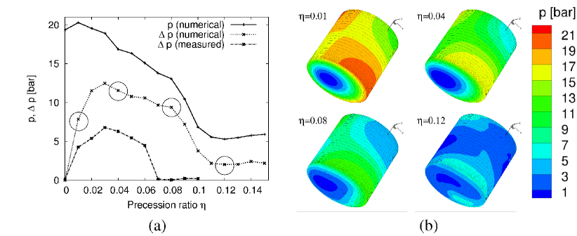
So far, we have achieved some qualitative, though not quantitative, agreement of the dominant flow structures between experiment and numerics for precessing cylindrical flows, at least for angles between precession and rotation axis not very far from 90∘. Basically, at low precession ratios ( is the angular velocity of precession) the flow is dominated by the first () Kelvin mode. Approximately at , higher azimuthal modes appear which start to draw more and more energy from the forced Kelvin mode. Still laminar, this regime breaks down suddenly at (details depend on the aspect ratio of the cylinder, the angle between rotation and precession axis, and the Reynolds number). We identified two global features by which this laminar-turbulent transition can be easily characterized. The first one is the energy dissipation, measurable by the motor power of the rotating cylinder (see [19]). The second one is the maximum pressure difference between opposite points on the side wall of the cylinder. Figure 1a shows the maximum pressure (numerically determined at ) and the maximum pressure difference (numerically determined at and experimentally at ), with all values up-scaled to the dimensions of the large machine. The right end-point, at , of the parabola-like part of the experimental curve, marks the sudden transition from the laminar to the turbulent regime. The corresponding numerical curve is qualitatively similar, but shows significant quantitative deviations, in particular a shift of the transition point towards higher values of . Note also that the maximum value of appears approximately at from where on the higher modes are increasingly fed by the forced mode.
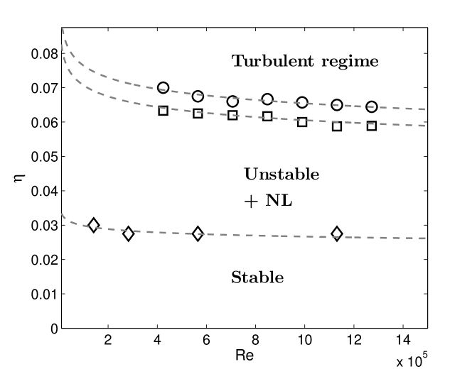
The effect of the Reynolds number on the various transitions found in our experiment is shown in Fig. 2. It shows also a first transition (diamonds) from a stable, -Kelvin-mode dominated flow to a more unstable flow comprising also higher -modes. The two upper lines indicate the laminar-turbulent transition, either coming from the laminar side (circles), or from the turbulent side (squares). The difference between the two lines indicates a hysteresis. The Reynolds number only weakly affects the transitions (an empirical curve fit for laminar-turbulent transition corresponds to ), raising hopes that the large machine might not behave dramatically different.
Interestingly, an intermediate regime characterized by the occurrence of a few medium-sized cyclones has been observed at the ATER experiment in Paris-Meudon [21]. So far, these vortex-like structures could not be identified at our water experiment. A 3-D, volumetric particle image velocimetry system currently being commissioned could ultimately provide a helicity distribution, which in turn could be fed to dynamo simulations. In general, we expect more conclusive dynamo predictions, in particular for the cyclonic and the turbulent regime, from a close interplay of water test measurements and advanced numerical simulations.
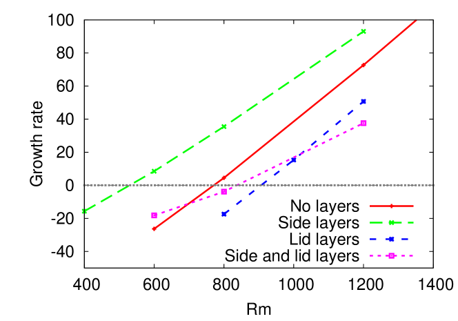
Up to present, dynamo action for precessing cylindrical flows has been confirmed in nonlinear simulations of the MHD equations for the case ( is the kinematic viscosity) and [18]. Yet, the critical depends on the specific electrical boundary conditions (see Fig. 3), with a surprisingly low optimum value of 550 for the case of electrically conducting side layers and insulating lid layers (actually, this finding has led us to consider an inner copper layer attached to the outer stainless steel shell of the dynamo vessel). Albeit this low critical is encouraging, the question of self-excitation in a real precession experiment is far from being settled. Further simulations at lower have led to an increase of the critical , and for lower values of dynamo action has not been confirmed yet (see also [22]).
2 Status of preparations
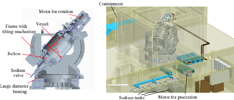
In contrast to previous dynamo experiments, the precession experiment has a higher degree of homogeneity since it lacks impellers or guiding blades and any magnetic material (the latter seems to play a key role for the functioning of the VKS dynamo [23]). The central precession module encases a sodium filled cylindrical volume of 2 m diameter and the same height (Figure 4). For this volume, we aim at reaching a rotation rate of 10 Hz (to obtain ), and a precession rate of 1 Hz (to cover both the laminar and the turbulent flow regimes). With total gyroscopic torques of up to Nm, we are in many respects at the edge of technical feasibility, so that much optimization work is needed to enable safe operation of the machine.
The complicated simultaneous rotation around two axes poses several challenges: filling and emptying procedures, heating and cooling methods, and handling of thermal expansion. A decision was made in favor of a slightly enlarged vessel, comprising two conical end-pieces that serve, first, for a well-defined filling and emptying procedure at 43∘ vessel tilting, and, second, for hosting two bellows which will compensate the thermal expansion of the liquid sodium.
Having defined this basic structure of the central vessel, much effort was, and still is, devoted to the optimization of the shell. A shell thickness of around 3 cm is needed anyway to withstand the centrifugal pressure of 20 bar in case of pure rotation (see Fig. 1). For increasing precession ratio, this total pressure decreases, but is complemented by a pressure vacillation due to the gyroscopic forces. In addition to those mechanical stresses, we also have to consider thermal stresses caused by the temperature difference over the shell when the dynamo is cooled by a strong flow of air. A particular problem is the high mechanical stress in the holes for the measurement flanges.
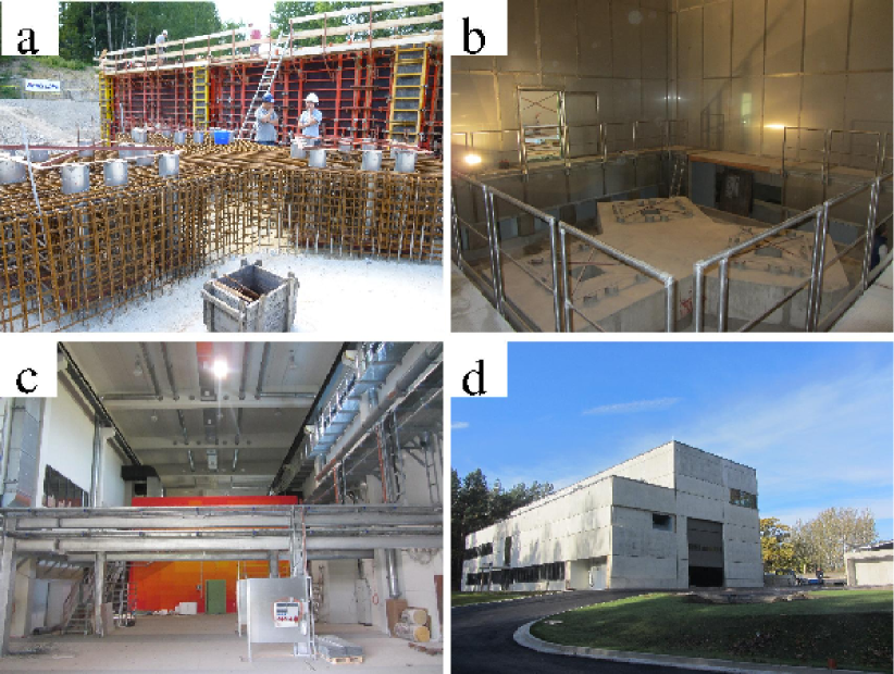
The next step is the design of the bearings and of a frame that allows to choose different angles between rotation and precession axis. Finding appropriate roller bearings for the vessel turned out to be extremely challenging, mainly because of the huge gyroscopic torque. It is the same gyroscopic torque that also requires a very stable basement (Fig. 5a,b), supported by seven pillars, each extending 22 m into the bedrock. The precession experiment itself is embedded in a containment (Fig. 4, Fig. 5b,c), preventing the rest of the building from the consequences of possible sodium leaks. Since the double rotation cannot be stopped quickly in case of an accident, this containment is the only chance of preventing jets that would spill out of a potential leak from perfectly covering all surrounding areas with burning sodium. For such accidents, the containment can be flooded with argon, which is stored in liquid form.
3 DRESDYN—What else is it good for?
Given the significant investment needed for the very precession experiment and the infrastructure to support it, we have combined this specific installation with creating a general platform for further liquid metal experiments.
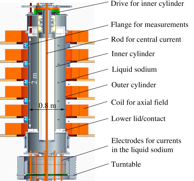
A second experiment relevant to geo- and astrophysics will investigate different combinations of the MRI and the current-driven TI (see Fig. 6). Basically, the set-up is a Taylor-Couette experiment with 2 m height, an inner radius cm and an outer radius cm. Rotating the inner cylinder at up to 20 Hz we plan to reach an of around 40, while the axial magnetic field will correspond to a Lundquist number of 8. Both values are about twice their respective critical values [24] for the standard version of MRI (with only an axial magnetic field applied).
Below those critical values, we plan to investigate how the helical version of MRI approaches the limit of standard MRI [25, 26]. To this end, we will use a strong central current, as it was already done in the PROMISE experiment [4, 5]. This insulated central current can be supplemented by another axial current, guided through the (rotating) liquid sodium, which will then allow to investigate arbitrary combinations of MRI and TI. Recent theoretical studies [27, 28] have shown that even a slight addition of current through the liquid would extend the range of application of the helical and azimuthal MRI to Keplerian flow profiles.
The TI will also play a central role in a third experiment in which different flow instabilities in liquid metal batteries (LMB) will be studied. LMB’s consist of three self-assembling liquid layers [29], an alkali or earth-alkali metal (Na, Mg), an electrolyte, and a metal or half-metal (Bi, Sb). In order to be competitive, LMB’s have to be quite large, so that charging and discharging currents in the order of some kA are to be expected. Under those conditions, TI and interface instabilities must be carefully avoided [30, 31].
Another installation is an In-Service-Inspection (ISI) experiment for various studies related to safety aspects of sodium fast reactors (SFR). In this context we also intend to investigate experimentally the impact of magnetic materials (e.g. ODS steels) on the mean-field coefficients in spiral flow configurations (see [32]), and its consequences for the possibility of magnetic-field self-excitation in the cores of SFR’s.
The construction of the DRESDYN building is well advanced. Figure 5c,d illustrate the status of the construction as of October 2014. The interior construction is expected to be finalized in 2015. Thereafter, installation of the various experiments can start. It goes without saying that both the precession and the MRI/TI experiment will be tested with water first, before we can dare to run them with liquid sodium.
4 Conclusions
We have discussed the motivation behind, and the concrete plans for a number of experiments to be set-up in the framework of DRESDYN. The new building and the essential parts of the experiments are expected to be ready in 2015. Apart from hosting the discussed experiments, DRESDYN is also meant as a general platform for further large-scale experiments, basically but not exclusively with liquid sodium. Proposals for such experiments are, therefore, highly welcome.
Acknowledgments
This work was supported by Helmholtz-Gemeinschaft Deutscher Forschungszentren (HGF) in frame of the Helmholtz Alliance ”Liquid metal technologies” (LIMTECH), and by Deutsche Forschungsgemeinschaft (DFG) under grant STE 991/1-2. We thank Jacques Léorat for his proposal and encouragement to set-up a precession driven dynamo. Fruitful discussions with Andreas Tilgner are gratefully acknowledged.
References
- [1] A. Gailitis et al. Detection of a flow induced magnetic field eigenmode in the Riga dynamo facility. Phys. Rev. Lett., vol. 84 (2000), pp. 4365-4368.
- [2] R. Stieglitz and U Müller. Experimental demonstration of an homogeneous two-scale dynamo. Phys. Fluids, vol. 13 (2001), pp. 561–564.
- [3] D.R. Sisan et al. Experimental observation and characterization of the magnetorotational instability. Phys. Rev. Lett., vol. 93 (2004), Art. No. 114502.
- [4] F. Stefani et al. Helical magnetorotational instability in a Taylor-Couette flow with strongly reduced Ekman pumping. Phys. Rev. E vol. 97 (2006), Art. No. 184502.
- [5] M. Seilmayer et al. Experimental evidence for non-axisymmetric magnetorotational instability in an azimuthal magnetic field . Phys. Rev. Lett. vol. 113 (2014), Art. No. 024505.
- [6] M. Seilmayer et al. Experimental evidence for a transient Tayler instability in a cylindrical liquid-metal column. Phys. Rev. Lett. vol. 108 (2012), Art. No. 024501.
- [7] M. Berhanu et a. Magnetic field reversals in an experimental turbulent dynamo. Europhys. Lett. vol. 77 (2007), Art. No. 59001.
- [8] F. Petrelis, S. Fauve, E. Dormy, and J.P. Valet. Simple mechanism for reversals of Earth’s magnetic field. Phys. Rev. Lett. vol.102 (2009), Art. No. 144503.
- [9] W.V.R. Malkus. Precession of Earth as cause of geomagnetism. Science, vol. 160 (1968), pp. 259–264.
- [10] R.F. Gans. On hydromagnetic precession in a cylinder. J. Fluid Mech., vol. 45 (1970), pp. 111–130.
- [11] J.P. Vanyo. Core-mantle relative motion and coupling. Geophys. J. Int., vol. 158 (2004), pp. 470–478.
- [12] A. Tilgner. Precession driven dynamo. Phys. Fluids, vol. 17 (2005), Art. No. 034104.
- [13] S.L. Shalimov. On the precession driven geodynamo. Izvestiya, Phys. Sol. Earth, vol. 42 (2005), pp. 460–466.
- [14] G. Consolini and P. De Michelis. Stochastic resonance in geomagnetic polarity reversals. Phys. Rev. Lett., vol. 90 (2003), Art. No. 058501.
- [15] C.A. Dwyer, D.J. Stevenseon, and F. Nimmo. A long-lived lunar dynamo driven by continuous mechanical stirring. Nature, vol. 220 (2012) pp. 47-61.
- [16] R.R. Fu et al. An ancient core dynamo in asteroid Vesta. Science, vol. 338 (2013) pp. 238-241.
- [17] A. Krauze. Numerical modeling of the magnetic field generation in a precessing cube with a conducting melt. Magnetohydrodynamics, vol. 46 (2010), pp. 271-280.
- [18] C. Nore, J. Léorat, J.L. Guermond, and F. Luddens. Nonlinear dynamo action in a precessing cylindrical container. Phys. Rev. E, vol. 84 (2011), Art. No. 016317.
- [19] F. Stefani et al.. DRESDYN - A new facility for MHD experiments with liquid sodium. Magnetohydrodynamics, vol. 46 (2010), pp. 271-280.
- [20] J. Léorat. Large scales features of a flow driven by precession. Magnetohydrodynamics, vol. 42 (2006), pp. 143-151.
- [21] W. Mouhali, T. Lehner, J. Léorat, and R. Vitry. Evidence for a cyclonic regime in a precessing cylindrical container. Exp. Fluids, vol. 53 (2012), 1693-1700.
- [22] A. Giesecke, T. Albrecht, G. Gerbeth, T. Gundrum, and F. Stefani. Numerical simulation for the DRESDYN precession dynamo. Magnetohydrodynamics, this issue (2015).
- [23] A. Giesecke, F. Stefani, and G. Gerbeth. Role of soft-iron impellers on the mode selection in the von Kármán-sodium dynamo experiment, Phys. Rev. Lett., vol. 104 (2010), Art. No. 044503.
- [24] G. Rüdiger, M. Schultz, and D. Shalybkov. Linear magnetohydrodynamic Taylor-Couette instability for liquid sodium. Phys. Rev. E, vol. 67 (2003), Art. No. 046312.
- [25] R. Hollerbach and G. Rüdiger. New type of magnetorotational instability in cylindrical Taylor-Couette flow . Phys. Rev. Lett., vol. 95 (2005), Art. No. 124501.
- [26] O.N. Kirillov and F. Stefani. On the relation of standard and helical magnetorotational instability. Astrophys. J., vol. 712 (2010), pp. 52-68.
- [27] O.N. Kirillov and F. Stefani. Extending the range of the inductionless magnetorotational instability. Phys. Rev. Lett., vol. 111 (2013), Art. No. 061103.
- [28] O.N. Kirillov, F. Stefani, and Y. Fukumoto. Local instabilities in magnetized rotational flows: a short-wavelength approach. J. Fluid Mech., in press (2014); arXiv:1401.8276.
- [29] H. Kim et al. Liquid metal batteries: Past, present, and future. Chem. Rev., vol. 113 (2013), 2075-2099.
- [30] N. Weber, V. Galindo, F. Stefani, T. Weier, and T. Wondrak. Numerical simulation of the Tayler instability in liquid metals. New J. Phys., vol. 15 (2013), Art. No. 043034.
- [31] N. Weber, V. Galindo, F. Stefani, and T. Weier. Current-driven flow instabilities in large-scale liquid metal batteries, and how to tame them. J. Power Sources, vol. 265 (2014), 166-173.
- [32] A. Giesecke, F. Stefani, and G.Gerbeth. Magnetic material in mean-field dynamos driven by small scale helical flows. New J. Phys., vol. 16 (2014), Art. No. 073034.