Relativistic Néel-order fields induced by electrical current in antiferromagnets
Abstract
We predict that a lateral electrical current in antiferromagnets can induce non-equilibrium Néel-order fields, i.e. fields whose sign alternates between the spin sublattices, which can trigger ultra-fast spin-axis reorientation. Based on microscopic transport theory calculations we identify staggered current-induced fields analogous to the intra-band and to the intrinsic inter-band spin-orbit fields previously reported in ferromagnets with a broken inversion-symmetry crystal. To illustrate their rich physics and utility, we considered bulk Mn2Au with the two spin sublattices forming inversion partners, and a 2D square-lattice antiferromagnet with broken structural inversion symmetry modeled by a Rashba spin-orbit coupling. We propose an AFM memory device with electrical writing and reading.
pacs:
75.50.Ee,75.47.-m,85.80.JmCommercial spin-based memory and storage devices rely on one type of magnetic order, ferromagnetism, and one basic principle, that the opposite spin orientations in a ferromagnet (FM) represent the 0’s and 1’s Chappert et al. (2007). Magnetic random access memory (MRAM) is a solid-state-memory variant of the hard disk where the magnetic medium for storing and the magnetoresistive read-element are merged into one. Unlike in hard disks, the magnetic stray field of the FM is not used for reading the FM bit and the latest spin–torque based MRAMs do not even use magnetic fields coupled to the FM moment for writing not (a). From this it appears natural to consider antiferromagnets (AFMs) as active building blocks of spintronic devices, where magnetic order is accompanied by a zero net magnetic moment Núñez et al. (2006); Shick et al. (2010); Jungwirth et al. (2011).
Antiferromagnets are attractive for spintronics because they offer insensitivity to magnetic field perturbations, produce no perturbing stray fields, are readily compatible with metal, semiconductor, or insulator electronic structure, can act as a magnetic memory, and can generate large magneto-transport effects Shvets et al. (2005); Park et al. (2011); Marti et al. (2013). For example, two distinct stable states of an AFM with orthogonal AFM spin-axis directions were set in an FeRh ohmic resistor and shown to be insensitive to fields as high as 9 T at ambient conditions Marti et al. (2014). A % AFM anisotropic magnetoresistance (AMR) was used to electrically detect the states, in complete analogy to the % AMR of NiFeCo based bits in the first generation of FM-MRAMs Daughton (1992). Also in analogy with the development of FM spintronics, very large (%) magnetoresistance signals were reported in AFM tunnel devices Park et al. (2011).
The AFM Néel-order spin-axis direction can be controlled indirectly by a magnetic field via an attached exchange-coupled FM Park et al. (2011); Marti et al. (2013) or, without the auxiliary FM, by techniques analogous to heat-assisted magnetic recording Petti et al. (2013); Marti et al. (2014). However, as with heat-assisted FM-MRAM not (b); Dieny et al. (2010), the speed and energy efficiency of this method are limited. Here we predict a novel mechanism for AFM spin-axis reorientation by a lateral electrical current via Néel-order spin-orbit torque (NSOT) fields, i.e., via non-equilibrium fields that alternate in sign between the two spin sublattices. This relativistic mechanism does not involve FMs, heating, or magnetic fields, and offers ultra-short times unparalleled in FMs.
The microscopic origin of our NSOT fields is analogous to the relativistic spin-orbit torques (SOTs) observed recently in magnets with broken bulk or structural inversion symmetry Bernevig and Vafek (2005); Manchon and Zhang (2008, 2009); Matos-Abiague and Rodriguez-Suarez (2009); Chernyshov et al. (2009); Garate and MacDonald (2009); Endo et al. (2010); Fang et al. (2011); Miron et al. (2010, 2011); Liu et al. (2012); Li et al. (2013); Garello et al. (2013); Kurebayashi et al. (2014), and is distinct in origin from the non-relativistic spin-transfer torques Ralph and Stiles (2008); Núñez et al. (2006); Gomonay and Loktev (2014). We demonstrate below two types of NSOTs in two model systems.
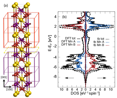
A field-like NSOT appears in Mn2Au AFM Shick et al. (2010); Wu et al. (2012); Barthem et al. (2013), whose MoSi2-type bct structure and AFM ordering are shown in Fig. 1(a). It is analogous to the field-like SOT arising from the inverse spin galvanic effect Bernevig and Vafek (2005); Manchon and Zhang (2008, 2009); Matos-Abiague and Rodriguez-Suarez (2009); Chernyshov et al. (2009); Garate and MacDonald (2009); Endo et al. (2010); Fang et al. (2011); Miron et al. (2010); Li et al. (2013), observed previously in broken inversion-symmetry paramagnets or FMs. However, Mn2Au is bulk centrosymmetric and the current-induced NSOT arises from the fact that the lattice can be divided into two sublattices, which, individually, have broken inversion symmetry and form inversion partners Zhang et al. (2014). Each sublattice gives opposite inverse spin galvanic effects, resulting in the NSOT field. The range of materials in which the relativistic current-induced torques can occur is therefore not restricted to FMs and, moreover, is not restricted to crystals with global broken inversion symmetry. In Mn2Au, the inversion partner sublattices coincide with the two AFM spin sublattices which makes the material an attractive candidate for observing the NSOT.
In AFMs where the two spin-sublattices do not form inversion partners a NSOT can still occur. We illustrate it below in a 2D square lattice where the same broken inversion symmetry term in the Hamiltonian is shared by both spin sublattices. Here the resulting NSOT is analogous to the intrinsic anti-damping SOT recently observed in broken bulk inversion symmetry FMs Kurebayashi et al. (2014).
Models and methods: In Mn2Au we diagonalized a microscopic multi-orbital tight-binding Hamiltonian to obtain the energy spectrum and eigenfunctions used in our transport calculations. The form of the tight-binding Hamiltonian was obtained following the procedure for bimetallic alloys described in Ref. Zemen et al. (2014). The accuracy of the tight-binding energy spectrum is confirmed in Fig. 1(b) by comparing the electronic structure to the ab initio density-functional theory (DFT) calculations.
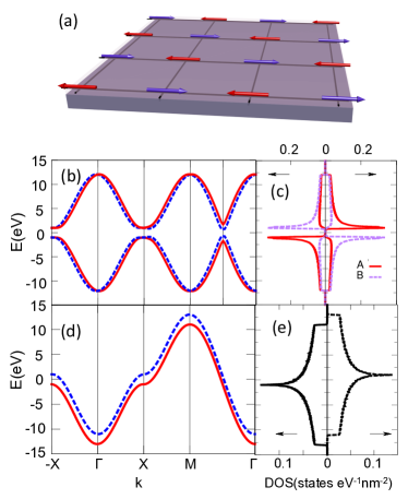
The other model structure comprises a 2D AFM square lattice with Rashba spin-orbit coupling due to the broken structural inversion symmetry and is relevant, e.g., to common experimental geometries in which a thin AFM film is interfaced with another layer. The model is sketched in Fig. 2(a) and its Hamiltonian is given by
| (1) |
Here is the local moment exchange constant, is the local moment – carrier exchange constant, is the tight binding Hamiltonian for the carriers, and is the Rashba spin-orbit interaction in a 2D system, given by
| (2) | |||||
where represents the spin-orbit coupling strength, and , label the nearest neighbors direction.
The current-induced nonequilibrium spin density can be calculated via the Kubo linear response Garate and MacDonald (2009):
| (3) |
where the Green’s functions are , with the property . Here, is the dimension of the 2D system, is the charge of electron, is the applied electric field, is the Fermi energy, is the energy spectrum, and is the spectral broadening that models the effect of disorder. For small , we can separate the total into the intra-band and inter-band contributions, with the intra-band term given by
| (4) |
Here denotes the expectation value of the carrier spin, and the velocity component along the current direction. This intra-band contribution in the Kubo formalism is equivalent to the Boltzmann transport theory expression Bernevig and Vafek (2005); Manchon and Zhang (2008, 2009); Garate and MacDonald (2009); Fang et al. (2011) and, similar to the charge conductivity, .
The inter-band contribution dominating in the clean limit of is given by Garate and MacDonald (2009),
| (5) | |||||
Here, the labels and correspond to different bands, and is Fermi distribution function.
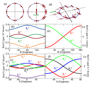
Results in Mn2Au: In Figs. 3(b),(c) we show the -independent intra-band NSOT field per applied current for Mn2Au. It is evaluated from Eq. (4) and projected on each sublattice, assuming AFM spin-axis rotation in the [100]-[010] plane ( corresponds to the [100] spin-axis direction) and in the [110]-[001] plane ( corresponds to the [110] easy-spin-axis in Mn2Au). Current is applied along the [100]-direction and the NSOT field is obtained from the non-equilibrium spin density considering a typical exchange-coupling energy scale in transition metals eV Haney et al. (2014).
NSOT fields on each sublattice are non-zero and have opposite sign. The largest component is in the plane in the direction perpendicular to the applied current for all AFM spin-axis directions. The magnitude of the NSOT field in the Mn2Au AFM is comparable to the counterpart SOT fields observed in FM transition metal structures. Note that for current along the direction the resulting NSOT field is zero.
The results imply that this intra-band NSOT is an AFM counterpart of the inverse spin galvanic effect Edelstein (1990), or the intra-band, field-like, SOT Bernevig and Vafek (2005); Manchon and Zhang (2008, 2009); Matos-Abiague and Rodriguez-Suarez (2009); Chernyshov et al. (2009); Garate and MacDonald (2009); Endo et al. (2010); Fang et al. (2011); Miron et al. (2010); Li et al. (2013), observed previously in broken inversion-symmetry, spin-orbit coupled paramagnets or FMs. We illustrate in Fig. 3(a) how these current induced non-equilibrium fields arise in structures with broken inversion symmetry. Here we choose the case of a Rasbha spin-orbit coupled 2D system for simplicity. The electric field induces an asymmetric non-equilibrium distribution function of carrier eigenstates and as a result a net polarization ensues that depends on the scattering time, hence its link to extrinsic scattering origin. In magnets, the non-equilibrium carrier spin density acts on magnetic moments as an effective magnetic field when carrier spins are exchange-coupled to the magnetic moments.
The full lattice of the Mn2Au crystal has an inversion symmetry and the first expectation would be that there is no current-induced spin-density. However, the lattice is formed by two sublattices which, individually, have broken inversion symmetry and form inversion partners along the [001] axis. These coincide with the spin sublattices of the AFM ground-state in Mn2Au, as highlighted in Fig. 1(a). The two sublattices forming the inversion partners in the Mn2Au crystal are at the origin of the observed intra-band NSOT.
Results in the model 2D Rasba AFM: Since both spin sublattices experience the same inversion symmetry breaking Rashba field in our 2D AFM model, the intra-band contribution to the current induced spin polarization has the same sign on both spin sublattices, i.e., is not staggered. A NSOT field is found, however, when evaluating the inter-band term from Eq. (5). The Néel-order current-induced field components projected on each sublattice are shown in Fig. 3(e),(f) for the AFM spin-axis rotation in the [100]-[010] plane and in the [100]-[001] plane. Here we plot the corresponding NSOT field per applied current along the [100]-direction.
The inter-band contribution described by Eq. (5) arises from the time-dependent quantum-mechanical perturbation of the eigenstates between collisions (illustrated in Fig. 3(d)) and is the basis of the Berry curvature mechanism introduced to explain the intrinsic anomalous Hall effect Nagaosa et al. (2010), the intrinsic spin-Hall effect Jungwirth et al. (2012), and most recently also the intrinsic anti-damping spin-orbit torque in FMs Kurebayashi et al. (2014); Freimuth et al. (2013). The key phenomenology which distinguishes the inter-band anti-damping spin-orbit field from the intra-band field is the harmonic dependence on the in-plane and out-of-plane spin-axis angles, as shown in Figs. 3(e),(f).
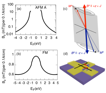
Another important feature, illustrated in Figs. 4(a),(b), is that the inter-band NSOT in the AFM can be significantly larger than its FM SOT counterpart. The inter-band nature of the term from Eq. (5) implies that its magnitude is large when two sub-bands linked by spin-orbit coupling have a small energy spacing. In the calculations shown in Figs. 3(e),(f) and 4(a),(b) for the model 2D lattice, we consider weak spin-orbit coupling relative to the exchange energy strength Kurebayashi et al. (2014). The smallest band splitting in this limit is governed by the exchange energy in the FM state while in the AFM state it is given by the small spin-orbit splitting. The band structures with their corresponding splittings are plotted in Fig. 2 together with the corresponding densities of states (DOSs) showing the characteristic van Hove singularities of the 2D square lattice. As shown in Figs. 4(a),(b), the inter-band current induced spin-orbit fields are enhanced in the vicinity of the DOS singularities in both the FM and AFM states. However, in the AFM state with the small energy spacing of the two spin-orbit coupled bands, the enhancement is much larger, reaching three orders of magnitude in the present calculations.
Discussion: In our 2D Rashba model we identified a relativistic microscopic mechanism by which an electrical current driven in a plane of an AFM layer with broken space-inversion symmetry generates an anti-damping NSOT. It acts on the sublattice magnetizations , in the form , where . The effective field is staggered in this case due to the opposite magnetizations on the two sublattices. This is reminiscent of an earlier phenomenological prediction of a non-relativistic anti-damping spin transfer torque (STT) generated in an AFM by an effective field due to a vertical spin-current from an adjacent FM layer polarized along a vector Gomonay and Loktev (2010). A detailed study of the corresponding Landau-Lifshitz-Gilbert (LLG) dynamics (assuming a fixed ) showed that above a critical current, at which the energy loss due to internal damping is compensated by the current-induced pumping, the configuration of becomes unstable and is switched to a stable state Gomonay and Loktev (2010). Because this is independent of the sign of the vertical current, the STT cannot switch the AFM back to the configuration. In the case of our anti-damping NSOT, is replaced with and a reversible 90∘ reorientation of the AFM can be achieved by redirecting the in-plane current between two orthogonal directions. Note that this favorable property of an anti-damping torque induced in the AFM by an in-plane current would apply not only to our relativistic NSOT but also to a spin-injection into the AFM from an adjacent paramagnet layer via the relativistic spin Hall effect Miron et al. (2011); Liu et al. (2012).
The field-like STT acting on the AFM in the FM/AFM bilayer has the form with , i.e., does not have the desired staggered property Gomonay and Loktev (2014). This illustrates why field-like non-relativistic STTs have been neglected in the LLG dynamics induced by an electrical current in AFMs. In our microscopic study of the Mn2Au we have demonstrated, however, that a field-like torque with a staggered and can be generated by current in special crystal structures in which the AFM spin sublattices coincide with the two inversion-partner sublattices. The corresponding dynamics comprising (damped) elliptical precessional motion with opposite helicities of the two spin sublattices is sketched in Fig. 4(c). For a detailed description of these modes we refer to Eq. (9) and the corresponding discussion in Ref. Keffer and Kittel (1952). Again, as in the anti-damping NSOT case, a cross-wire geometry can be used to reversibly switch between two orthogonal AFM spin-axis directions using the field-like NSOT. For the theoretical (001)-plane anisotropy energies in Mn2Au Shick et al. (2010), our estimates of the NSOT fields suggest sizable reorientations at current densities A/cm2, depending on the angle of the applied in-plane current with respect to the easy and hard anisotropy axes.
Ultra-fast (ps-scale) reorientation of the AFM spin-axis in a staggered field was previously reported in an optical pump-and-probe study of AFM TmFeO3 Kimel et al. (2004). The origin of the staggered field was different than considered here; the material had a temperature dependent AFM easy-axis direction and the corresponding Néel-order anisotropy field was induced by laser-heating the sample above the easy-axis transition temperature. The microscopic origin of the staggered field is not crucial, however, for the time-scale of the spin-dynamics which in AFMs is typically 2-3 orders of magnitude shorter than in FMs Keffer and Kittel (1952). We can therefore infer from these experiments that the AFM spin-axis reorientation due to our current-induced NSOT will not be limited by the ultra-fast AFM spin dynamics itself but only by the circuitry time-scales for delivering the electrical pulses which can be of order ps Schumacher et al. (2003). A schematic of a device that can be used to reverse the AFM spin-axis electrically between two orthogonal directions is illustrated in Fig. 4(d). In a cross-wire geometry, each wire stabilizes via the NSOT one of the two orthogonal spin-axis directions. An AFM-AMR Marti et al. (2014, 2013) measured in one of the arms can then be used to electrically detect the spin-axis direction. In an AFM with cubic magnetic anisotropy, an all-electrical AFM memory device can be realized based on this scheme.
We acknowledge fruitful discussions with R. Campion, K. Edmonds, A. Ferguson, B. Gallagher, X. Marti, V. Novak, K. Olejnik, H. Reichlova, A. Rushforth, H. Saidaoui, and P. Wadley, and support from the EU European Research Council (ERC) advanced grant no. 268066, from the Ministry of Education of the Czech Republic grant no. LM2011026, from the Grant Agency of the Czech Republic grant no. 14-37427G, from the Academy of Sciences of the Czech Republic Praemium Academiae, from the NSF grant no. DMR-1105512, ONR grant no. 141110780, and the Alexander Von Humboldt Foundation. A.M. was supported by the King Abdullah University of Science and Technology
∗ The authors contributed equally.
References
- Chappert et al. (2007) C. Chappert, A. Fert, and F. N. V. Dau, Nature Mat. 6, 813 (2007).
- not (a) www.everspin.com/PDF/ST-MRAM_Technical_Brief.pdf.
- Núñez et al. (2006) A. S. Núñez, R. A. Duine, P. Haney, and A. H. MacDonald, Phys. Rev. B 73, 214426 (2006).
- Shick et al. (2010) A. B. Shick et al., Phys. Rev. B 81, 212409 (2010).
- Jungwirth et al. (2011) T. Jungwirth et al., Phys. Rev. B 83, 035321 (2011).
- Shvets et al. (2005) I. V. Shvets, A. N. Grigorenko, K. S. Novoselov, and D. J. Mapps, Appl. Phys. Lett. 86, 212501 (2005).
- Park et al. (2011) B. G. Park et al., Nature Mater. 10, 347 (2011).
- Marti et al. (2013) X. Marti et al., Nature Commun. in press.
- Marti et al. (2014) X. Marti et al., Nature Mater. 13, 367 (2014).
- Daughton (1992) J. M. Daughton, Thin Solid Films 216, 162 (1992).
- Petti et al. (2013) D. Petti et al., Appl. Phys. Lett. 102, 192404 (2013).
- not (b) E. Fullerton, S. Maat, and J. U. Thiele, U.S. patent 20050281081 (2005).
- Dieny et al. (2010) B. Dieny et al., Int. J. Nanotechnol. 7, 591 (2010).
- Bernevig and Vafek (2005) B. A. Bernevig and O. Vafek, Phys. Rev. B 72, 033203 (2005).
- Manchon and Zhang (2008) A. Manchon and S. Zhang, Phys. Rev. B 78, 212405 (2008).
- Manchon and Zhang (2009) A. Manchon and S. Zhang, Phys. Rev. B 79, 094422 (2009).
- Matos-Abiague and Rodriguez-Suarez (2009) A. Matos-Abiague and R. L. Rodriguez-Suarez, Phys. Rev. B 80, 094424 (2009).
- Chernyshov et al. (2009) A. Chernyshov et al., Nature Phys. 5, 656 (2009).
- Garate and MacDonald (2009) I. Garate and A. H. MacDonald, Phys. Rev. B 80, 134403 (2009).
- Endo et al. (2010) M. Endo, F. Matsukura, and H. Ohno, Appl. Phys. Lett. 97, 222501 (2010).
- Fang et al. (2011) D. Fang et al., Nature Nanotech. 6, 413 (2011).
- Miron et al. (2010) I. M. Miron et al., Nature Mater. 9, 230 (2010).
- Miron et al. (2011) I. M. Miron et al., Nature 476, 189 (2011).
- Liu et al. (2012) L. Liu et al., Science 336, 555 (2012).
- Li et al. (2013) H. Li, X. Wang, F. Dogan, and A. Manchon, Appl. Phys. Lett. 102, 192411 (2013).
- Garello et al. (2013) K. Garello et al., Nature Nanotech. 8, 587 (2013). eprint arXiv:1301.3573.
- Kurebayashi et al. (2014) H. Kurebayashi et al., Nature Nanotech. 9, 211 (2014).
- Ralph and Stiles (2008) D. C. Ralph and M. D. Stiles, J. Magn. Magn. Mater. 320, 1190 (2008).
- Gomonay and Loktev (2014) E. V. Gomonay and V. M. Loktev, Low. Temp. Phys. 40, 17 (2014).
- Wu et al. (2012) H. Wu et al., Adv. Mater. 24, 6374 (2012).
- Barthem et al. (2013) V. M. T. S. Barthem, C. V. Colin, H. Mayaffre, M. Julien, and D. Givord, Nat. Commun. 4, 2892 (2013).
- Zhang et al. (2014) X. Zhang et al., Nature Phys. 10, 387 (2014).
- Zemen et al. (2014) J. Zemen et al., J. Magn. Magn. Mater. 356, 87 (2014).
- Haney et al. (2014) P. M. Haney et al., Phys. Rev. B 88, 214417 (2014).
- Edelstein (1990) V. M. Edelstein, Solid State Commun. 73, 233 (1990).
- Nagaosa et al. (2010) N. Nagaosa et al., Rev. Mod. Phys. 82, 1539 (2010).
- Jungwirth et al. (2012) T. Jungwirth, J. Wunderlich, and K. Olejnik, Nature Mater. 11, 382 (2012).
- Freimuth et al. (2013) F. Freimuth, S. Blügel, and Y. Mokrousov (2013).
- Gomonay and Loktev (2010) H. V. Gomonay and V. M. Loktev, Phys. Rev. B 81, 144427 (2010).
- Keffer and Kittel (1952) F. Keffer and C. Kittel, Phys. Rev. 85, 329 (1952).
- Kimel et al. (2004) A. V. Kimel et al., Nature 429, 850 (2004).
- Schumacher et al. (2003) H. W. Schumacher et al., Phys. Rev. Lett. 90, 017201 (2003).