The Scission-Point Configuration within the Two-Center Shell Model Shape Parameterization
Abstract
Within the two-center shell model parameterization we have defined the optimal shape which fissioning nuclei attain just before the scission and calculated the total deformation energy (liquid drop part plus the shell correction) as function of the mass asymmetry and elongation at the scission point. The three minima corresponding to mass symmetric and two mass asymmetric peaks in the mass distribution of fission fragments are found in the deformation energy at the scission point. The calculated deformation energy is used in quasi-static approximation for the estimation of the total kinetic and excitation energy of fission fragments and the total number of emitted prompt neutrons. The calculated results reproduce rather well the experimental data on the position of the peaks in the mass distribution of fission fragments, the total kinetic and excitation energy of fission fragments. The calculated value of neutron multiplicity is somewhat larger than experimental results.
pacs:
02.60.Lj, 02.70.Bf, 21.60.Cs, 21.60.EvI Introduction
In the theory of nuclear fission the quasistatic quantities like the potential energy surface, the ground state energy and deformation, the fission barrier height, etc., are often calculated within the macroscopic-microscopic method Str66 ; brdapa . In this method the total energy of the fissioning nucleus consists of the two parts, macroscopic and microscopic. Both parts are calculated at fixed shape of nuclear surface. In the past a lot of shape parameterizations were proposed and used. A good choice of the shape parameterization is often the key to the success of the theory. Usually, one relies on physical intuition for the choice of the shape parameterization.
A method to define the shape of nuclear surface which does not rely on any shape parameterization was proposed by V. Strutinsky in stlapo ; strjetp45 . In this approach the shape of an axial, left-right symmetric nucleus was defined by looking for the minimum of the liquid-drop energy under the additional restrictions that fix the volume and elongation of the drop.
Recently the method was further developed fivan08 ; ivapom2 by incorporating of the axial ivpoba ; ivapom4 and left-right asymmetry and the neck degree of freedom of the nuclear shape procedia ; fivan14 .
The important result of the Strutinsky procedure stlapo is the possibility to definite in a formal way the scission point as the maximal elongation at which the nucleus splits into two fragments.
Having at one’s disposal the shape and the deformation energy at the scission point in present work we have tried to evaluate the measurables of the fission experiments like mass distribution, the total kinetic and excitation energy of fission fragments, the multiplicity of prompt neutrons.
A similar investigation was carried out in a recent work cahaivta where the experimental results for reaction were described in terms of three fission modes.
The paper is organized as follows. Section II contains a short overview of Strutinsky prescription stlapo for the optimal shapes. The shapes that correspond to the minimum of liquid-drop energy within the two-center shell model shape parameterization are presented in Section III. The account of the shell correction and their influence on the total excitation energy of fission fragments are discussed in Section IV. The comparison of the calculated and experimental results for the total kinetic energy of fission fragments and multiplicity of prompt neutrons for the fission of and by thermal neutrons is given in Section V. Sect. VI contains short summary.
II Optimal shapes
In stlapo the shape of a left-right and axial symmetric nucleus was described by some profile function . The shape of the surface was obtained then by rotating the curve around the -axis. A formal definition of was obtained by searching for the minimum of the liquid-drop energy, , under the constraint that the volume and the elongation are fixed,
| (1) |
with
| (2) |
In (1) and are the corresponding Lagrange multipliers. The elongation parameter was chosen in stlapo as the distance between the centers of mass of the left and right parts of the nucleus, see (2).
Since both Coulomb and surface energy are functionals of the variation in (1) results in an integro-differential equation for
| (3) |
Here is the Coulomb potential at the nuclear surface and is the fissility parameter of the liquid drop bohrwhee ,
| (4) |
where is the surface tension coefficient, see Eq. (6). In (4) and everywhere below the index (0) refers to the spherical shape.
By solving Eq. (3) for given and ( is fixed by the volume conservation condition) one obtains the profile function which we refer to as the optimal shape. Varying parameter one obtains a full variety of shapes ranging from a very oblate shape (disk, even with central depression) up to two touching spheres. Few examples of optimal shapes are shown in Fig. 1.

The liquid drop deformation energy
| (5) |
(in units of the surface energy for a spherical shape)
| (6) |
calculated with optimal shapes is shown in Fig. 2 as function of the elongation parameter . Note, that the spherical shape corresponds to . In (5)
| (7) |
where is the radius of the spherical nucleus.

One can see from Fig. 2 that the elongation of the shapes shown in these figures is limited by some maximal value . With a good accuracy the maximal deformation is independent of the fissility parameter , for . Above this deformation mono-nuclear shapes do not exist. This maximal deformation was interpreted in stlapo as the scission point.
The different branches of the energy shown in Fig. 2 correspond to the different values of fissility parameter . Along each lower branch the shape of the drop changes from sphere to spheroid, then to the shape with the neck which is getting smaller until the maximal elongation , see Fig. 1. The shapes at the maximal elongation are shown in the right part of Fig. 2. It turns out that at each fixed the shape itself does not depend much on the fissility parameter.
Another peculiarity of Fig. 2 is the upper branches of the deformation energy at large deformation. Along these branches the neck of the drop becomes smaller and smaller until the shape turns into two touching spheres.
It turns out, however, that the upper branch of the deformation energy corresponds not to the minimum of but to its maximum (Eq.(1) holds true both at the minimum and maximum of the liquid-drop energy). This can be easily verified by adding to the optimal profile function some small perturbation and calculating the deformation energy with perturbed profile function . Thus, the upper branch of corresponds to the ridge of the potential energy surface in the coordinates elongation and neck thickness.
III The optimal shapes within two-center shell model parameterization
The two-center shell model parameterization (TCSMP) maruhn is at present the only parameterizations which describes both compact shapes and separated fragments. It is successfully used by few groups in the description of fission-fusion process based on the Langevin equations for the shape parameters, see wada ; aritomo ; arichi ; antonenko and references therein.
The two-center shell model potential includes the central part , and terms. The central part consists of two oscillator potentials smoothly joined by the fourth order polynomial, see Fig. 3. The sharp surface is defined as that given by the equipotential surfaces of potential , i.e. by the equation . The constant is found from the requirement that the volume inside sharp surface is equal to the volume of spherical nucleus.
Within TCSMP the shape is characterized by 5 deformation parameters: the distance between the centers of left and right oscillator potentials, the mass asymmetry parameter , the deformations and of the left and right oscillator potentials and the neck parameter . Here and are the masses of heavy and light fragments (in case of the shape separated into two fragments) or the masses of the right and left parts of the compact nucleus. Within TCSMP the shape is divided in parts by the point . Please, note, that and fix the deformation of potential only in ”outer” region, namely for or . The deformation of whole fragments depends not only on and but on all other parameters, and .

By solving the Langevin equations the number of parameters is often reduced to 3 in order to diminish the computation time. The parameters and are assumed to be the same , and the neck parameter is kept constant. Here we would like to note, that constant does not mean constant neck radius. Within TCSMP the neck radius depends on all 5 deformation parameters. Even by variation of only one deformation parameter one gets quite reasonably class of shapes of fissioning nucleus.
Having at one’s disposal the optimal shapes is of a certain interest to check how good is the two-center shell model parameterization. For this purpose we compare in Fig. 4 the liquid-drop deformation energy calculated with the optimal shapes (3) and the two-center shell model parameterization for the symmetric splitting () and mass asymmetry that corresponds to the position of the main peak in the mass distribution of fission fragments of considered in this work nuclei . The deformation energy is plotted as a function of (2). In case of two-center shell model parameterization the deformation energy was minimized with respect to , and keeping constant the distance between the centers of mass of left and right part of nucleus.

As one can see from Fig. 4, the TCSMP is rather accurate. In case of symmetric splitting () the difference between the deformation energy calculated with optimal shape and TCSMP does not exceed 0.4 . The optimal value of parameter varies somewhat with and at large deformations is close to . For the mass asymmetry the difference between the deformation energy calculated with optimal shape and TCSMP is somewhat larger. In the barrier region it is of the order of 0.8 .
At present and in the past a lot of calculations were done with the restricted set of TCSM shapes, namely putting . In order to check how good is this approximation we have carried out the minimization of the liquid-drop energy within TCSMP with restriction (dot line in Fig. 4). In this case the difference between the deformation energy calculated with optimal shape and TCSMP is of the order of 1.6 at the barrier.
At the scission point the difference between the deformation energy calculated with optimal shape and TCSMP is very small, it does not exceed few hundred even in case. Since in present work we examine the deformation energy at the scission point configuration the use of TCSMP seems quite justified.
Since the TSCMP describes both compact and separated shapes, it is interesting to check what will be the optimal shape within TSCMP beyond . For this purpose we carry out the minimization of the liquid drop energy within TCSMP with respect to and keeping fixed for . The result is shown in Fig 5. Instead of continuous decreasing of the neck to zero, the shapes suddenly splits into two fragments at relatively thick neck, .

The shape of the fragments ”immediately after scission” is very close to the spheres. This is confirmed by the comparison in Fig. 6 of the Coulomb and surface energy of left and right parts of the drop with these of the two separated spheres. Notice, that at the scission point the Coulomb energy changes continuously, only the surface energy changes abruptly to the smaller value.
The ”jump” of the surface energy to smaller value at the scission point causes the corresponding jump in the liquid-drop energy, see. Fig. 7.
The deformation energy shown in Fig. 7, differs from the published so far results by the presence of jump at critical elongation. This jump is a consequence of using a special (though very clear) quantity for measure of elongation of nucleus - the distance between centers of mass of left and right parts and requirement that


other deformation parameters are found from the minimization of liquid-drop energy at given . These other parameters (the distance , the neck parameter and the deformation of fragments) change abruptly at to ensure that the energy is minimal on both side of . Without minimization one usually consider the continuous change of the deformation parameters on the whole potential energy surface.
The possibility to define the critical deformation in a formal way has at least two important consequences: it clearly indicates at which deformation the dynamical calculations should be stopped, and it makes to calculate the primary excitation energy of the fission fragments during the scission. The difference of the deformation energy ”just before scission” () and ”immediately after scission” ()
| (8) |
can characterize the excitation energy available for emission of prompt neutrons and -quanta by the fission fragments. Here by ”just before scission” and ”immediately after scission” we call the configuration with infinitely smaller or larger than .
IV The account of shell effects
For accurate calculation of the excitation energy released in result of neck rupture the account of shell effects is very important. Besides, one should consider the possible mass asymmetry of the fission fragments.
In Figs. 8-9 we show the liquid-drop and the total (liquid-prop plus the shell correction including the shell correction to the pairing energy)
| (9) |
deformation energy for nucleus . The summation in (9) is carried out over the protons () and neutrons().
The was defined in a usual way as the difference between the sum of single particle energies of occupied states and the averaged quantity,
| (10) |
Here is the averaged density of single-particle states,
| (11) |
with being the density of single-particle states,
| (12) |
The chemical potential is defined by the particle number conservation condition
| (13) |
where is the particle number (neutrons or protons). The is Strutinsky smoothing function brdapa ,
| (14) |
In (14) are the Hermite polynomials. The smoothing width and the degree of correcting polynomial are the parameters of the averaging procedure. They were fixed by the so called ”plateau condition”.
The shell correction to the pairing energy was defined as the difference between the pairing energy in BCS approximation, ,
| (15) |
and the averaged part ,
| (16) |
The and in (15) are fixed by the particle number conservation and the gap equation.
We define following brdapa , i.e. by replacing the sum in (15) by the integral and assuming that the density of state is constant over the pairing window
The pairing strength was removed from (IV) by solving the gap equation in the same approximation,
| (18) |
For the average pairing gap we used the approximation suggested in moller92
| (19) |
with .
The parameter of TCSMP can be expressed as a function of . The parameters, , were found by the minimization of the liquid-drop energy at fixed and .
For the calculation of the shell correction the optimal TCSMP shape was expanded in series in deformed Cassini ovaloids (up to 20 deformation parameters were included). For the shape given in terms of Cassini ovaloids the shell model code pash71 with deformed Woods-Saxon potential was used to calculate the single-particle energies and the shell correction .
Please, note that the shape in the above calculations was defined by the minimization of the liquid-drop energy. The shell correction was added afterwards to the optimal liquid-drop energy. Thus, the available class of shapes was defined by the liquid-drop properties of system. The influence of shell structure on the available class of shapes was ignored. For example, the configuration with one fragment being almost spherical and another very elongated due to the shell effects is not possible to obtain by the minimization of liquid-drop energy. Such configuration leads to a second mass-asymmetric minimum in the potential energy surface of actinide nuclei and has a considerable influence on the mass distribution of fission fragments.
In principle, one could minimize the total (liquid-drop plus shell correction) energy within TCSM parameterization keeping fixed and . However, such procedure is very time consuming. That is why, below we follow more closely the optimal shapes procedure fivan14 and introduce an additional freedom for the shape of fissioning nucleus by minimization of the liquid-drop energy with additional constraints
| (20) |
Here and are the quadrupole moments of the left and right parts of nucleus. The and are the smoothed constraining operators for the elongation and mass asymmetry fivan14 .
The energy (20) was minimized numerically with respect to parameters and keeping fixed the elongation , mass asymmetry (or mass of heavy fragment ) and the Lagrange multipliers . Thus, the maximal elongation , the shape and the energy at become dependent on and .
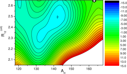
In Fig. 10 we show the maximal elongation and the total deformation energy at for as function of and .
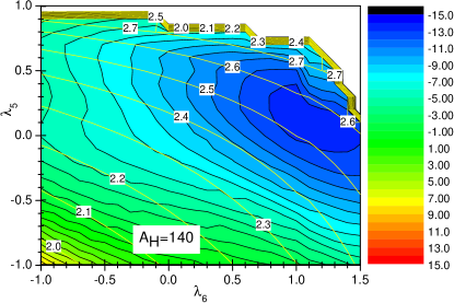
First of all, one can see that due to the shell effects the scission point configuration with the lowest total energy corresponds not to but to some finite values of and .
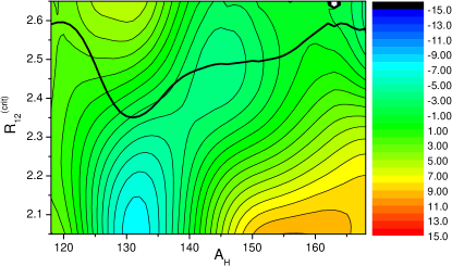
In order to show the dependence of the total energy (and the shell correction ) on the maximal elongation , the lowest energy at fixed (the point with the lowest energy along yellow contour line in Fig. 10) from the total energy surface shown in Fig. 10 was picked up. After such minimization we get the total energy and the shell correction as function of one variable . This procedure was carried out for each value of the mass asymmetry. In this way, the optimal scission point in space was found by the minimization of the total energy on the class of shapes given by the solution of Eq. (20).
The additional constraints and were introduced in order to find the scission shape that corresponds to the smallest total (liquid-drop plus shell correction) energy. Thus, the configuration space in should be large enough to include the point of minimal total energy. For each value of mass asymmetry we have checked if the point of minimal total energy is inside of chosen - space. If such point turned out to be at the edge of - space, the limiting values of or were increased. Once the point of minimal total energy is inside of chosen - space, the results of calculation are not sensitive to the size of - space since the contributions of the points away from minimum are suppressed by the exponential factor in (22).
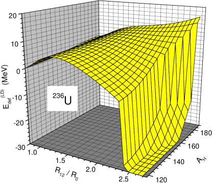
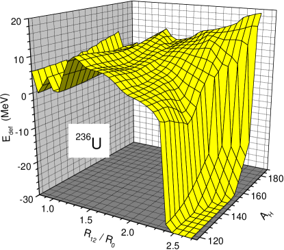
The shell correction and the total deformation energy of are shown in Figs. 11, 12 as function of the heavy fragment mass number and the elongation at critical deformation.
The three minima, two at mass asymmetric deformation and and one at symmetric deformation are clearly seen in the deformation energy shown in Figs. 11, 12. The minimum at is responsible for the main peak in the mass distribution of the fission fragments in the reaction . The second mass asymmetric minimum contributes to the satellite in the mass distribution. This minimum gives the main contribution to the maximum of the total kinetic energy (TKE) of fission fragments at . The reason is clear looking at mean value
| (21) |
shown in Fig. 11 by heavy solid curve. The is the most probable distance between the centers of mass of left and right parts of nucleus at critical deformation (just before scission). The averaging in (21) is done with the canonical distribution in the space of variables , see (22) below.
The Coulomb repulsion energy and, consequently, the total kinetic energy of fission fragments is defined mainly by the distance between the centers of mass of fragments. At the asymmetries where is maximal, the is minimal, and, on the contrary, is maximal where is minimal (at in the considered case).
V Numerical results
Keeping in mind that fission is a slow process, one could assume that during the fission process the state of the fissioning nucleus is close to statistical equilibrium, i.e. each point on the deformation energy surface is populated with a probability given by the canonical distribution,
| (22) |
Here is a parameter characterizing the width of the distribution (22) in the space of deformation parameters. The energy in (22) is the sum of the liquid-drop deformation energy (5) and of the shell correction , shown in Fig. 10. Here, is the mass asymmetry of fissioning system and are the rest of collective parameters (elongation , and Lagrange multipliers and ).
The distribution (22) is a basic assumption of the scission-point model suggested in spm and developed further in spm2 ; spm3 ; spm4 , see also krapom . The parameters of this model were fitted in spm to reproduce the numerous experimental data. The was found to be close to . In the calculations shown below we use somewhat larger value =1.5 MeV.
We are aware that, in principle, the distribution (22) should depend not only on the deformation energy but on the collective velocities too. The kinetic prescission energy estimated in this work can reach in case of reaction. However, even in this case the collective kinetic energy per particle () is much smaller than the single-particle kinetic energies. So, the approximation (22) seems quite reasonable.
The normalized mass distribution of the fission fragments can be expressed then in terms of the deformation energy at the critical deformation ,
| (23) |
The summation in (23) is carried out over the Lagrange multipliers which correspond to the same . The rest of deformation parameters of TCSMP were fixed by the minimization of the liquid-drop energy at .
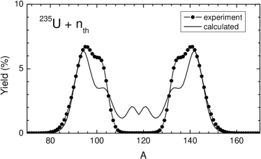
The calculated mass distribution (22)-(23) of the fission fragments for the reaction is compared with the experimental data zeynalov06 in Fig. 13. Please note, that the information on the deformation energy at the scission point does not suffice to calculate the width of mass distribution. The width parameter of the distribution (22) is a free parameter in present approach. In Fig. 13, like in all other calculations in this work, we used the value . The calculated mass distribution is rather close to the experimental results. The presence and the position of two mass asymmetric peaks are reproduced rather well. However, at the symmetric splitting the calculated values are much larger as compared with experiment. The reason for such discrepancy is at present not clear.
The comparison of the calculated for few fission reaction with the available experimental results is shown in Fig. 14. In these calculations we define as the sum of the Coulomb interaction of spherical fragments immediately after scission and the prescission kinetic energy ,
| (24) |
Here
| (25) |
where and are the charges of light and heavy fragments. The summation in (25) is carried out over and . Like in fivan14 we define the from the energy balance
| (26) |

i.e. we assume the ”complete acceleration”: the energy difference between the saddle and scission turns into the kinetic energy of relative motion of fragments, no dissipation takes place. The opposite extreme case would be the assumption of overdamped motion: all the energy difference between the saddle and scission turns into the heat, no prescission kinetic energy. The incident neutron energy term has been dropped in Eq. (26) since it very small, .
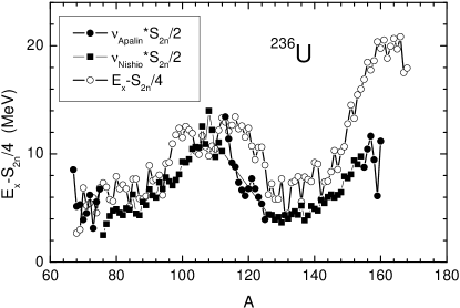
The comparison of the calculated and measured values of shown in Fig. 14 is in favor of ”complete acceleration”. Without contribution from the (dash curve in Fig. 14) would be too small. The neglecting of dissipation for the fission by thermal neutrons can be also justified by referring to the calculations of the friction coefficient within the linear response theory. It was shown in ivahof that at small excitations (when the pairing correlations are still important) the friction coefficient is negligibly small.
Note, that the calculated is rather close to experimental data. The position of maximum of and the drop at symmetric splitting are also well reproduced. This can be considered as a confirmation that the potential energy just before scission and the mean value of are defined correctly.
The is one of two parts of the total energy release , . The -value is the difference of the ground state energies
| (27) |
To calculate the ground state energy besides mass numbers of fission fragments (or ) one should know also their charge numbers (or ). In the calculations shown in Fig. 14 we considered a Gaussian distribution of charge numbers wahl characterized by the most probable charge and the width parameter ,
| (28) |
The value of parameters and was taken from litaize , , with and, for heavy fragment, with and being the mass and charge number of mother nucleus. Here stands for the integer part of .
The -value does not depend on dynamics, it can be calculated within the macroscopic-microscopic method or taken from the existing databases. Since the experimental value of is rather well reproduced by the present calculations, the calculated total excitation energy should be also quite accurate. The average value of TXE
| (29) |
is shown in Fig. 15.

For the comparison the excitation energy due to the difference of the liquid-drop energy (8) just before the scission and immediately after the scission is plotted by dash line. The contribution of to the total excitation energy of fission fragments varies from 85 (for ) to 60 (for ). The rest is the contribution from the shell effects.
The fragments are de-excited by the emission of neutrons and -rays. When the excitation energy is smaller than neutron separation energy the -quanta are emitted. The energy available for -emission varies from to zero. So, on average the excitation energy available for neutron emission is given by . The average value of the total number of prompt neutrons can be estimated by the relation
| (30) |
In order to calculate the dependence of on the fragments mass number one needs to know how the excitation energy is shared between the fragments. Here we split the last stage of the fission into two steps. On first step the rapid neck rupture takes place. The nucleus turns into two fragments with the same mass asymmetry and the same distance between centers of mass as just before scission. The shape of the fragments immediately after scission is assumed to correspond to the minimum of the liquid drop energy. It was shown in procedia that the optimal shape of the fragments placed at the distance is very close to two spheres. The contribution to energy from quadrupole and higher order deformation is smaller that and can be neglected. So, in present work we assume that immediately after scission the two spherical fragments are formed. The energy immediately after scission consists of the energy of light and heavy spherical fragments plus the energy of their Coulomb interaction,
| (31) |
The primary excitation energy is shared between the fragments. In the recent work cahaivta the partition of the excitation energy between the light and the heavy fragments was calculated both in the thermalization immediately after scission hypothesis () madnix and in the sudden approximation caharise . The effect of these two hypothesis on the mass split is quite opposite. While the sudden approximation predicts the lighter fragment to be more excited, the contrary is in the case of thermalization. The difference of the excitation energy of light and heavy fragment is not so large, only few MeV. So, for simplicity we will assume here that the excitation energy of light and heavy fragments due to the neck rupture is the same. This excitation energy for is shown in Fig. 16b.
On the second stage of fission process the fragments relax to the ground state shape and gain some extra deformation energy
| (32) |

Extra deformation energy is shown in Fig. 16d as function of fragments mass number. Eventually, the total excitation energy of one fragment is given by the sum
| (33) |
see Fig. 16e.
In Fig. 17 we compare the excitation energy available for the prompt neutron emission, with the experimental value of neutron multiplicity apalin ; nishio multiplied by the half of two-neutron separation energy (in order to remove the rapid fluctuations due to the odd-even effect in ). One can see that there is some discrepancy up to 5 at large mass asymmetries, but on the average the saw-tooth structure is rather well reproduced.
Having at one’s disposal the excitation energy one can calculate the total excitation energy
| (34) |
and the total number of prompt neutrons
| (35) |
The simple approximation to (35) is given by (30). In (35) the multiplicity of emitted neutrons is calculated for each value of and summed in with the weight given by the calculated mass distribution of fission fragments. In (30) the total neutron multiplicity is defined as the ratio of the total excitation energy to the average neutron separation energy.
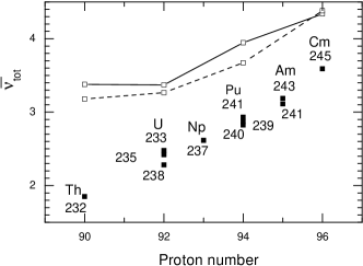
The comparison of calculated with the available experimental results is shown in Fig. 18. On average the dependence of on the proton number of fissioning nuclei is qualitatively reproduced. The calculated value of are however larger than experimental by (0.5-0.9). The source of this discrepancy can be related to the use of very simple estimate (30) for the neutron multiplicity and use of the quasistatic approximation (22) for the mass distribution. In particular, too large value of for symmetric splitting, see Fig. 16e is not confirmed by the experimental results.
VI Summary
The calculations carried out in present work show that the optimal shape prescription offers a good possibility to define the shape of fissioning nuclei just before the scission. This information can be used for the evaluation of the quantities which are measured in fission experiments like the mass distribution, the total kinetic and excitation energy of fission fragments, the multiplicity of prompt neutrons. The calculated distributions of the total kinetic energy for fission of and were found to be in rather good agreement with the experimental data.
The sawtooth structure of the neutron multiplicity is well reproduced. The dependence of total multiplicity of prompt neutrons on proton number of fissioning nucleus is reproduced only qualitatively.
The reason for the discrepancy between calculated and experimental results for average total prompt neutron multiplicities may be too crude approximation of Eqs. 26, 31 for the relation between the excitation energy and neutron multiplicity. There could be also other reasons, like the use of assumption that each point on the deformation energy surface is populated with a probability given by the canonical distribution (22).
For the mass distribution of fission fragments the position of the peaks is reproduced rather well. The width and strength of peaks of calculated mass distribution differ substantially from the experimental data. For more accurate description of mass distribution the dynamical approach to the fission process seems necessary.
Acknowledgements.
This paper includes the results of “Comprehensive study of delayed-neutron yields for accurate evaluation of kinetics of high-burn up reactors” entrusted to Tokyo Institute of Technology by the Ministry of Education, Culture, Sports, Science and Technology of Japan (MEXT). The authors appreciate very much the fruitful discussions with Profs. N. Carjan, A. Iwamoto, K. Nishio and K. Pomorski. One of us (F. I.) would like to express his gratitude to the Tokyo Institute of Technology, for the hospitality during his stay at Japan.References
- (1) V. M. Strutinsky, Nucl. Phys. 3, 449 (1966); Nucl. Phys. A95, 420 (1967); Nucl. Phys. A122, 1 (1968).
- (2) M. Brack, J. Damgaard, A.S. Jensen, H.C. Pauli, V.M. Strutinsky and C.Y. Wong, Rev. Mod. Phys. 44, 320 (1972).
- (3) V.M. Strutinsky, N.Ya. Lyashchenko, N.A. Popov, Nucl. Phys.46, 639 (1963).
- (4) V.M. Strutinsky, Zh.Exp.Theor.Fiz. 45, 1891 (1963).
- (5) F.Ivanyuk, Int. J. Mod. Phys. E 18, 130 (2009).
- (6) F.A. Ivanyuk and K. Pomorski, Phys. Rev. C 79, 054327 (2009).
- (7) F.A. Ivanyuk, K. Pomorski, J. Bartel, Int. J. Mod. Phys. E 21, 1250032 (2012).
- (8) F.A. Ivanyuk, K. Pomorski, Phys. Scr. T 154, 014021 (2013).
- (9) F.A. Ivanyuk, Physics Procedia 47, 17 (2013).
- (10) F.A. Ivanyuk, Phys. Scr. 89, 054012 (2014).
- (11) N. Carjan, F.-J. Hambsch, F.A. Ivanyuk, P. Talou, sumitted to Physics Procedia.
- (12) N. Bohr and J. A. Wheeler, Phys. Rev. 56 (1939) 426.
- (13) J.Maruhn and W.Greiner, Z.Physik 251, 431 (1972).
- (14) T. Asano, T. Wada, M. Ohta, T. Ichikawa, S. Yamaji, and H. Nakahara, J. Nucl. Radiochem. Sci. 5, 1 (2004).
- (15) Y. Aritomo and M. Ohta, Nucl. Phys. A 744, 3 (2004).
- (16) Y. Aritomo and S. Chiba, Phys. Rev. C 88, 044614 (2013).
- (17) A. Diaz-Torres, N.V. Antonenko, W. Scheid, Nucl. Phys. A 652, 61 (1999).
- (18) P. Moller, Nucl. Phys. A 536, 20 (1992).
- (19) V.V. Pashkevich, Nucl. Phys. A 169, 275 (1971).
- (20) B.D. Wilkins, E.P. Steinberg, and R.R. Chasman, Phys. Rev. C 14, 1832 (1976).
- (21) J. Moreau, K. Heyde, and M. Waroquier, Phys. Rev. C 28, 1640 (1983).
- (22) A. Ruben, H. Marten, D. Seeliger, Zeit.für Physik A Hadrons and Nuclei 338, 67 (1991).
- (23) S. Panebianco, J.-L. Sida, H. Goutte, J.-F. Lemaitre, N. Dubray, and S. Hilaire, Phys. Rev. C 86, 064601 (2012).
- (24) H.-J. Krappe and K. Pomorski, Theory of Nuclear Fission, Springer Verlag, Heidelberg, 2012.
- (25) A.I. Sergachev, V.G. Vorob’eva, B.D. Kuz’minov, V.B. Mikhailov, M.Z. Tarasko Yad. Fiz. 7, 778 (1968).
- (26) F.-J. Hambsch, H.-H Knitter, C. Budtz-Jorgensen and J. Theobald, Nucl. Phys. A 491, 56 (1989).
- (27) C. Tsuchiya, Y. Nakagome, H. Yamana, H. Moriyama, K. Nishio, I. Kanno, K. Shin, I. Kimura, J. Nucl. Sc. Techn. 37, 941 (2000).
- (28) C. Wagemans, E. Allaert, A. Deruytter, R. Barthelemy, P. Schillebeeckx, Nucl. Phys. A 380, 61 (1982).
- (29) K. Nishio, Y. Nakagome, I. Kanno, I. Kimura, J. Nucl. Sc. Techn. 32, 404 (1995).
- (30) A. Ramaswami, S. Prakash, S. B. Manohar, S.P. Dange, P.P. Venkatesan, and M.V. Ramaniah, Phys. Rev. C 16, 716 (1977).
- (31) F.A. Ivanyuk, H. Hofmann, Nucl. Phys. A 657, 19 (1999).
- (32) A.C. Wahl, R.L. Ferguson, D.R. Nethaway, D.E. Troutner, K. Wolfsberg, Phys. Rev. C 126, 1112 (1962).
- (33) O. Litaize and O. Serot, Phys. Rev. C 82, 054616 (2010).
- (34) D.G. Madland, J.R. Nix, Nucl. Sci. Eng. 81, 213 (1982).
- (35) N. Carjan, F.-J. Hambsch, M. Rizea and O. Serot, Phys. Rev. C 85, 044601 (2012).
- (36) V.F. Apalin et al., Nucl. Phys. 71, 553 (1965).
- (37) K. Nishio et al., Nucl. Phys. A 632, 540 (1998).
- (38) S. Zeynalov, V. Furman, F.-J. Hambsch, M. Florec, V.Yu. Konovalov, V.A. Khryachkov and Yu.S. Zamyatnin, in Proceedings of the 13th International Seminar on Interaction of Neutrons with Nuclei (ISINN-13), Dubna, Russia, May 25-28, 2005 (Joint Institute for Nuclear Research, Dubna, 2006), p. 351.
- (39) T. Ohsawa, J. Nucl. Radiochem. Sci. 9, 19 (2008).