∎
2Computational Learning and Motor Control Lab, University of Southern California, Los Angeles, CA 90089, USA
33institutetext: Alexander Herzog 44institutetext: Autonomous Motion Dept., Max-Planck Inst. Intelligent Systems, 72076 Tübingen, Germany
44email: aherzog@tuebingen.mpg.de
Momentum Control with Hierarchical Inverse Dynamics on a Torque-Controlled Humanoid
Abstract
Hierarchical inverse dynamics based on cascades of quadratic programs have been proposed for the control of legged robots. They have important benefits but to the best of our knowledge have never been implemented on a torque controlled humanoid where model inaccuracies, sensor noise and real-time computation requirements can be problematic. Using a reformulation of existing algorithms, we propose a simplification of the problem that allows to achieve real-time control. Momentum-based control is integrated in the task hierarchy and a LQR design approach is used to compute the desired associated closed-loop behavior and improve performance. Extensive experiments on various balancing and tracking tasks show very robust performance in the face of unknown disturbances, even when the humanoid is standing on one foot. Our results demonstrate that hierarchical inverse dynamics together with momentum control can be efficiently used for feedback control under real robot conditions.
Keywords:
Whole-Body Control Multi-Contact Interaction Hierarchical Control Inverse Dynamics Force Control Humanoid1 Introduction
111Part of the material presented in this paper has been presented at the 2014 IEEE/RSJ International Conference on Intelligent Robots and SystemsWe expect autonomous legged robots to perform complex tasks in persistent interaction with an uncertain and changing environment (e.g. in a disaster relief scenario). Therefore, we need to design algorithms that can generate precise but compliant motions while optimizing the interactions with the environment. In this context, the choice of a control strategy for legged robots is of primary importance as it can drastically improve performance in the face of unexpected disturbances and therefore open the way for agile robots, whether they are locomoting or performing manipulation tasks.
Robots with torque control capabilities Boaventura:2012tc ; Hutter:2012uu , including humanoids Cheng:2008tw ; Moro:2013 ; Ott:2011uj , are becoming increasingly available and torque control algorithms are therefore necessary to fully exploit their capabilities. Indeed, such algorithms often offer high performance for motion control while guaranteeing a certain level of compliance Boaventura:2012tc ; Kalakrishnan:2011dy ; Saab:2013vr ; Salini:2011bw . In addition, they also allow for the direct control of contact interactions with the environment Hutter:2012uu ; Righetti:2013tt ; righetti11b , which is required during operation in dynamic and uncertain environments. Recent contributions have also demonstrated the relevance of torque control approaches for humanoid robots Hyon:2007jya ; Ott:2011uj ; Stephens:2010vu . We can essentially distinguish two control approaches.
Passivity-based approaches on humanoids were originally proposed in Hyon:2007jya and recently extended in Ott:2011uj . They compute admissible contact forces and control commands under quasi-static assumptions. The great advantage of such approaches is that they do not require a precise dynamic model of the robot. Moreover, robustness is generically guaranteed due to the passivity property of the controllers. However, the quasi-static assumption can be a limitation for dynamic motions.
On the other hand, controllers based on the full dynamic model of the robot have also been successfully implemented on legged robots Hutter:2012uu ; Righetti:2013tt ; Stephens:2010vu ; Mason:2014 ; Vaillant:2014cl . These methods essentially perform a form of inverse dynamics. The advantage of such approaches is that they are in theory well suited for very dynamic motions. However, sensor noise (particularly in the velocities), limited torque bandwidth and the need for a precise dynamic model make them more challenging to implement. Moreover, it is generally required to simplify the optimization process to meet time requirements of fast control loops (typically 1 kHz on modern torque controlled robots). Although there are many contributions showing the potential of such approaches in simulation Faraji:2014 ; Feng:2014 ; Kuindersma:2014 ; Salini:2011bw , evaluations on real robots are still rare due to the lack of torque controlled humanoid platforms and the complexity in conducting such experiments.
Extensions of the inverse dynamics approach have been proposed where it is also possible to control hierarchies of tasks using the full dynamics of the robot. The main advantage is that it is possible to express complicated behaviors directly at the task level with a strict enforcement of hierarchies between tasks. It is, for example, useful to ensure that a balancing task will take precedence over a task of lower importance in case of conflicting goals. Early hierarchical approaches are based on pseudo-inverse techniques Sentis:2005 and take inspiration directly from techniques used for manipulators Nakamura:1987 . However, pseudo-inverse-based controllers are limited as they cannot properly handle inequality constraints such as torque limits or friction cone constraints. More recently, generalizations have been proposed deLasa:2010hf ; Saab:2013vr ; Mansard:2012gy ; Escande:2014en that naturally allow the inclusion of arbitrary types of tasks including inequalities. The resulting optimization problems are phrased as cascades of quadratic programs (QPs). Evaluation of their applicability was done in simulation and it has been shown that these algorithms are fast enough to be implemented in a real-time fast control loop for inverse kinematics. It has also been argued that they can be implemented fast enough for the use with inverse dynamics and can work on robots with model-uncertainty, sensor noise and limited torque bandwidth. But to the best of our knowledge, these controllers have never been used as feedback-controllers on real torque-controlled humanoids.
In Saab:2013vr , the trajectories computed in simulation are replayed on a real robot using joint space position control, but the method is not used for feedback control in task-space on the robot. This work is very interesting because it demonstrates that trajectories generated by a hierarchical inverse dynamics are such that they can be used on a real system. However, it is important to note that this does not show that feedback control can be done using these controllers. Indeed, when replaying trajectories, feedback is reduced to joint level tracking. Therefore it is not possible to directly control interaction forces during multi-contact tasks or to close a feedback loop directly around the tasks of interests, for example the center of gravity (CoG), that respects the desired hierarchies. It is worth mentioning that Hutter:2012uu recently successfully implemented a controller using the full dynamics of the robot and task hierarchies on a torque controlled quadruped robot. The approach is based on pseudo-inverses and not QPs which makes it potentially inefficient to handle inequalities (e.g. friction cone constraints, torque saturation, center of pressure constraints, etc…).
During balancing and walking tasks, an appropriate control of the CoG is of major importance. Recently, it has been realized that the control of both the linear (i.e. the CoG) and angular momentum of the robot could be very beneficial for balancing and walking tasks. The control of overall momentum was originally proposed in Kajita:2003gj using a resolved rate control framework and it was recently extended in Lee:2012hb where it was integrated with an inverse dynamics controller. It has been shown in several contributions Wensing:2013 ; Lee:2012hb that the regulation of momentum could be very powerful for control on humanoids. Despite the growing popularity for momentum-based control approaches, there have been very few evaluations of such techniques on a real humanoid robot Stephens:2010vu . In Stephens:2010vu the momentum-based control is computed using a simplification of the optimization problem and does not necessarily generate the optimal command. Moreover, the control command generated from inverse dynamics is used in conjunction with a joint PD controller and not used as the sole feedback controller of the system (i.e. there are two distinct feedback pathways, one coming from the momentum control through inverse dynamics and the other coming from desired joint positions at the joint level). To the best of our knowledge a momentum-based controller has never been evaluated either in a complete hierarchical inverse dynamics framework or without additional joint PD stabilization.
As advanced torque control techniques are developed there is a need to evaluate these techniques on torque-controlled platform to assess their capabilities and also their drawbacks. Such an evaluation is the main goal of the paper. In a recent contribution herzog:2014b , we have demonstrated that hierarchical inverse dynamics controllers could be efficiently used on a torque-controlled humanoid robot. In particular, we demonstrated robust performance during balancing and tracking tasks when using a momentum-based balance control approach. We also proposed a method to simplify the optimization problem by factoring the dynamics equations of the robot such that we could significantly reduce computational time and achieve a 1 kHz control-loop.
Contribution
In this contribution, we extend our preliminary work and present extensive experimental evaluations. First, we show modifications we applied to the algorithm, originally proposed by deLasa:2010hf ; Kanoun:2011ey , that were necessary to execute it in a real-time feedback control setting for inverse dynamics tasks (Section 2). We also propose a method to systematically compute the feedback gains for the linear and angular momentum control task by using a linear optimal control design approach (Section 3). This leads us to the main contribution of this paper, where we show experiments with extensive quantitative analysis for various tasks (Sections 4 and 5). We show that the momentum-based controller with optimal feedback gains can improve robot performance. Balancing experiments in various conditions demonstrate performances that are comparable to, if not better than, current state of the art balancing algorithms, even when the robot is balancing on one foot. Tracking and contact switching experiments also show the versatility of the approach. It is, to the best of our knowledge, the first demonstration of the applicability of the methods proposed in deLasa:2010hf or Saab:2013vr as feedback controllers on torque controlled humanoids (i.e. without joint space PD control) with the use of a momentum-based control approach. In the last section, we discuss the experimental results as compared to the state of the art.
2 Hierarchical Inverse Dynamics
In this section, we detail our modeling assumptions, give a short summary on how tasks can be formulated as desired closed-loop behaviors and revisit the original solver formulation deLasa:2010hf . In Section 2.3 we then propose a simplification to reduce the complexity of the original formulation. The simplification is also applicable to any other inverse dynamics formulation.
2.1 Modelling Assumptions and Problem Formulation
In the following, we describe the constraints and tasks that are considered by the hierarchical inverse dynamics. They will all be written as affine functions of joint and body accelerations, joint torques and contact forces in order to formulate the control problem as a series of quadratic programs. They constitute the variables that will be optimized by the controller.
Rigid Body Dynamics
Assuming rigid-body dynamics, we can write the equations of motion of a robot as
| (1) |
where denotes the configuration of the robot. is the vector of joint positions and denotes the position and orientation of a frame fixed to the robot with respect to an inertial frame (the floating base). is the inertia matrix, is the vector of all non-contact forces (Coriolis, centrifugal, gravity, friction, etc.), represents the underactuation, is the vector of commanded joint torques, is the Jacobian of the contact constraints and are the generalized contact forces.
Contact constraints
End effectors are constrained to remain stationary. We express the constraint that the feet (or hands) in contact with the environment do not move () by differentiating it twice and using the fact that . We get the following equality constraint
| (2) |
Center of pressure
To ensure stationary contacts, the center of pressure (CoP) at each end effector needs to reside in the interior of the end effector’s support polygon. This can be expressed as a linear inequality by expressing the ground reaction force at the zero moment point.
Friction cone
For the feet not to slip we constraint the ground reaction forces (GRFs) to stay inside the friction cones. In our case, we approximate the cones by pyramids to have linear inequality constraints in the contact forces.
Torque and joint limits
Especially important for generating control commands that are valid on a robot is to take into account actuation limits . The same is true for joint limits, which can be written as , where the bounds are computed in the form .
Motion and force control tasks
Motion controllers can be phrased as
,
where is the task Jacobian and
is a reference task acceleration that will
correspond to a desired closed-loop behavior (e.g. obtained from a
PD-controller). Desired contact forces can be directly expressed as
equalities on the generalized forces . In
general, we assume that each control objective can be expressed as a
linear combination of , and
, which are the optimization variables of
our problem.
At every control cycle, the equations of motion (Equation (1)), the constraints for physical consistency (torque saturation, CoP constraints, etc.) and our control objectives are all expressed as affine equations of the variables . Tasks of the same priority can then be stacked vertically into the form
| (3) | ||||
| (4) |
where , , , , and the overall task dimensions and the number of robot DoFs. is the number of constrained end effectors.
The goal of the controller is to find , and (and therefore a control command) that satisfies these objectives as well as possible. Objectives will be stacked into different priorities, with the highest priority in the hierarchy given to physical consistency. In a lower priority, we will express balancing and motion tracking tasks and we will put tasks for redundancy resolution in the lowest priorities.
2.2 Hierarchical Tasks & Constraints Solver
The control objectives and constraints in Equations (3) and (4) might not have a common solution, but need to be traded off against each other. In case of a push, for instance, the objective to decelerate the CoG might conflict with a swing foot task. A tradeoff can be expressed in form of slacks on the expressions in Equations (3),(4). The slacks are then minimized in a quadratic program. We propose an algorithm that is a combination of the methods originally proposed in deLasa:2010hf ; Kanoun:2011ey .
| (5) | |||||
| s.t. | (6) | ||||
| (7) | |||||
where matrices weigh the cost of constraints against each other and are slack variables. Note that are not predefined, but part of the optimization variables. The objective is regularized by a small value (typically ), which ensures positive definiteness of the objective hessian. In the remainder, we write the weighted tasks using .
Although allow us to trade-off control objectives against each other, strict prioritization cannot be guaranteed with the formulation in Equation (5). For instance, we might want to trade off tracking performance of tasks against each other, but we do not want to sacrifice physical consistency of a solution at any cost. In order to guarantee prioritization, we solve a sequence of QPs, in which a QP with constraints imposed by lower priority tasks is optimized over the set of optimal solutions of higher priority tasks as proposed by Kanoun:2011ey . Given one solution for the QP of priority , all remaining optimal solutions in that QP are expressed by the equations
| (8) | |||
| (9) | |||
where represents a surjective mapping into the nullspace of all previous equalities , and is a variable that parameterizes that nullspace. We compute from a Singular Value Decomposition (SVD). With this nullspace mapping we reduce the number of variables from one hierarchy level to the next by the number of locked degrees of freedom. In our implementation the SVD is computed in parallel with the QP at priority level and rarely finishes after the QP, i.e. it adds only a negligible overhead.
Now, we can express a QP of the next lower priority level and additionally impose the constraints in Equations (8), (9) in order to optimize over without violating optimality of higher priority QPs:
| (10) | |||||
| s.t. | |||||
| (11) | |||||
where we wrote the QP as in Equation (5) and substituted into the objective function. In order to ensure that we optimize over the optimal solutions of higher priority tasks, we added Equation (9) as an additional constraint and substituted Equation (8) into Equations (10)-(11). This allows us to solve a stack of hierarchical tasks recursively as originally proposed by Kanoun:2011ey . Right-multiplying to inequality matrices creates zero rows for constraints that do not have degrees of freedom left. For example, after the GRFs are decided, CoP and friction constraints become obsolete. This way the number of inequalities reduces potentially from one QP to the other. Note that this optimization algorithm is guaranteed to find the optimal solution in a least-squares sense while satisfying priorities.
With this formulation we combine the two benefits of having inequalities in all hierarchical levels Kanoun:2011ey and reducing the number of variables from one QP to the other deLasa:2010hf .
2.3 Decomposition of Equations of Motion
Hierarchical inverse dynamics approaches usually have in common that consistency of the variables with physics, i.e. the equations of motion, need to be ensured. In deLasa:2010hf these constraints are expressed as equality constraints (with slacks) resulting in an optimization problem over all variables . In Mansard:2012gy a mapping into the nullspace of Equation (1) is obtained from a SVD on Equation (1). In both cases, complexity can be reduced as we will show in the following. We decompose the equations of motion as
| (12) | |||||
| (13) |
where Equation (12) is just the first equations of Eq. (1) and Equation (13) is the last equations related to the floating base. The latter equation can then be interpreted as the Newton-Euler equations of the whole system Wieber:2006up . They express the change of momentum of the robot as a function of external forces. A remarkable feature of the decomposition in Equations (12), (13) is that the torques only occur in Equation (12) and are exactly determined by in the form
| (14) |
Since is linearly dependent on , for any combination of accelerations and contact forces there always exists a solution for . It is given by Equation (14). Therefore, it is only necessary to use Equation (13) as a constraint for the equations of motion during the optimization (i.e. the evolution of momentum is the only constraint).
Because of the linear dependence, all occurrences of in the problem formulation (i.e. in Equations (3)-(4)) can be replaced with Equation (14). This reduces the number of variables in the optimization from to . This decomposition thus eliminates as many variables as there are DoFs on the robot. This simplification is crucial to reduce the time taken by the optimizer and allowed us to implement the controller in a 1 kHz feedback control loop.
Remark 1
The simplification that we propose222We originally proposed the simplification in a technical note herzog:2013a . can appear trivial at first sight. However, it is worth mentioning that such a decomposition is always ignored in related work despite the need for computationally fast algorithms deLasa:2010hf , Mansard:2012gy , Stephens:2010vu .
2.4 Solution to the first priority
Since we are interested in writing inverse dynamics controllers, we set the highest priority tasks to always be the Newton-Euler Equations (Equation (13)) together with torque saturation constraints. We then need to find the space of solutions for equations
| (15) | |||
| (16) |
with given by Equation (14), and . In this case, we can obtain the space of solutions (cf. Equation (8)) without having to solve a QP. A trivial solution can be readily obtained, thus reducing computation time. Indeed, it is always possible to satisfy the equations of motion together with the torque saturation constraints exactly by choosing and resolving for using Equation (1). The resulting solution will be in the set of minimizers, i.e.
| (17) | |||||
| (18) |
with computed as described in Section 2.2. We can then obtain , which is required to construct the QP for priority . Although may violate torque saturation constraints, Equations (17), (18) guarantee that an admissible can always be found and will be found in the following QPs. With this choice of there is no need to invert . Note that represents the Newton-Euler equations of the system and is always of full row rank 333The part of multiplying the base acceleration is always full rank. and thus computing requires only inverting the sized positive definite matrix . By designing the first hierarchy level in this way, we can improve computation time by avoiding to solve the first QP while already reducing the size of the problem by 6 variables for the next priority.
3 Linear and angular momentum regulation
As we mentioned in the introduction, we are interested in writing desired feedback behaviors using hierarchical inverse dynamics and more specifically, we are interested in controlling the linear and angular momentum of the robot. The feedback controller that regulates momentum is often written as a PID controller with hand-tuned gains. Such control design does not take into account the coupling between linear and angular momentum during a multi-contact task and can potentially lead to a controller which is sub-optimal and difficult to tune.
In this section, we write the momentum regulation problem as a force control task and then use a simple LQR design to compute a linear optimal feedback control law. This feedback law is then used to compute a desired closed-loop behavior in the hierarchical inverse dynamics controller. The advantage of such design is that it fully exploits multi-contacts and momentum coupling while significantly simplifying the design of the controller by reducing the number of open parameters.
3.1 Linear and angular momentum models
The control of momentum and CoG is inherently both a kinematic and a force task. Indeed, using the centroidal momentum matrix Orin:2008ge , one can find a linear mapping between the overall robot momentum and the robot joint and pose velocities
| (19) |
where is the system linear and angular momentum expressed at the CoG. The matrix is called the centroidal momentum matrix. The derivative of Equation (19) allows us to express the rate of change of the momentum and the CoG
| (20) |
This formulation has been often used in a resolved acceleration scheme where the centroidal momentum matrix is viewed as the task Jacobian (e.g. in Lee:2012hb ).
Using the Newton-Euler equations, the total change of momentum can also be written in terms of the external forces
| (21) |
where is the gravitational force, the vector of generalized external forces, maps a vector to a skew symmetric matrix, s.t. and is the position of the contact point.
We see that the rate of momentum change can equivalently be written either as a kinematic task (i.e. a function of as in Equation (20)) or a force task (i.e. a function of as in Equation (21)). The matrix in front of or is viewed as the Jacobian of the task.
In general, deriving a momentum control law with Equation (21) might be better because we do not have to compute , which usually is acquired through numerical derivation and might suffer from magnified noise. In addition, in Equation (21) external forces can be interpreted as the control inputs of the system, which is a useful interpretation for control design, as we explain below.
3.2 LQR design for momentum control
A desired momentum behavior is typically achieved using a PD control law, for example
where and are reference momentum and CoG trajectories. Using Equation (20), a desired closed-loop behavior is then added in the hierarchical inverse dynamics as
There are, however, several issues with such an approach. First, the tuning of the PD controller can be problematic. In our experience, on the real robot it is necessary to have different gains for different contact configurations to ensure proper tracking which leads to a time consuming process with many open parameters. Second, such a controller does not exploit the coupling between linear and angular momentum rate of change that is expressed in Equation (21).
We propose to use the model of Equation (21) to compute optimal feedback gains. We linearize the dynamics and compute a LQR controller by selecting a desired performance cost. We find a control law of the form
| (25) |
that contains both feedback and feedforward terms. A desired closed-loop behavior for the momentum that appropriately takes into account the momentum coupling is then computed. The desired task used in the hierarchical inverse dynamics controller is then written as
| (28) |
We project the control into the momentum space such that we can use the available redundancy during multi-contact tasks to optimize the internal forces further. It would not be possible if we used directly Equation (25).
The proposed approach takes into account the coupling between linear and angular momentum, which will prove beneficial in the experimental section. Moreover, we specify the performance cost once and for all and the feedback gains are computed optimally for every contact and pose configuration of the robot at a low computational cost. In our experience, it drastically simplified the application on the real robot.
Remark 2
In our experiments, we use an infinite horizon LQR design and compute gains for key poses of the robot, one for each contact configurations. During a contact transition we interpolate between the old and new set of gains to ensure continuous control commands. This solution is not ideal from a theoretical point of view as the interpolation does not guarantee stable behavior, but it works well in practice. Indeed, the contact transitions are very fast and all the trajectories were planned in advance. It would also be straightforward to linearize the dynamics at every control sequence and use a receding horizon controller with time-varying gains to allow online replanning of desired trajectories.
4 Experimental Setup
In this section, we detail the experimental setup, the low-level feedback torque control, the state estimation algorithm and the limitations of the hardware. These details are important in order to understand the strengths and limitations of the presented experiments. They should also ease the reproduction of the experimental results on other platforms.
4.1 Sarcos Humanoid Robot
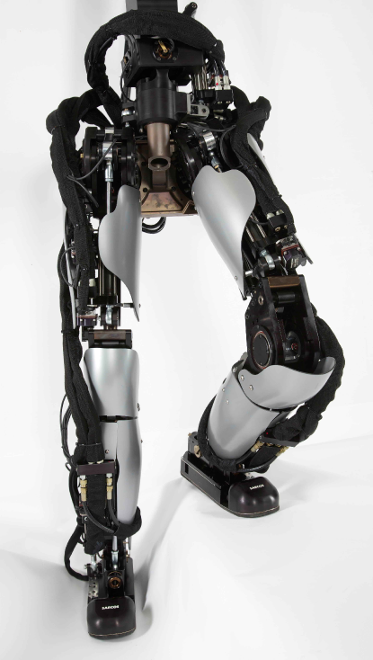
The experiments were done on the lower part of the Sarcos Humanoid Robot Cheng:2008tw , shown in Figure 1. It consists of two legs and a torso. The legs have 7 DoFs each and the torso has 3 DoFs. Given that the torso supports a negligible mass, because it is not connected to the upper body of the robot and its motion does not significantly influence the dynamics, we froze these DoFs during the experiments. The legs of the robot are 0.82m high. Each foot is 0.09m wide and 0.25m long. Note also that the front of the foot is made of a passive joint that is rather flexible, located 10cm before the tip of the foot. Moving the CoP across this link makes the foot bend and causes the robot to fall. This makes the effectively used part of the sole rather small for a biped. The total robot mass is 51kg.
The robot is actuated with hydraulics and each joint consists of a Moog Series 30 flow control servo valve that moves a piston. Attached to the piston is a load cell to measure the force at the piston. A position sensor is also located at each joint. Each foot has a 6-axis force sensor and we mounted an IMU on the pelvis of the robot from which we measure angular velocities and linear accelerations of the robot in an inertial frame. An offboard computer sends control commands to the robot and receives sensor information in real-time at 1 kHz. The control commands consist of the desired current applied to each valve. We used a computer running a linux kernel patched with Xenomai 2.6.3 for real-time capabilities.
4.2 Low-level torque control
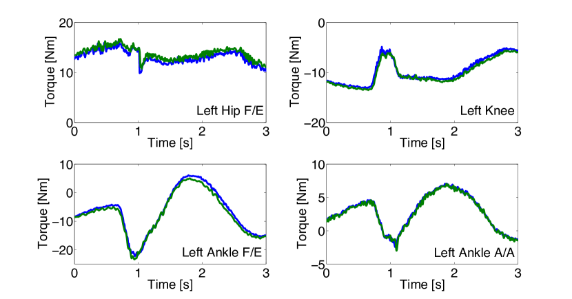
For each actuator, we implemented a torque feedback controller that ensures that each joint produces the desired force generated by the hierarchical inverse dynamics controller. The controller essentially computes desired flow directly in terms of valve current. The controller we implemented is very much inspired from the work in Boaventura:2012tc ; Boaventura:2012va , with the difference that we implemented a simpler version where piston velocity feedback has a constant gain. The constant gain allows us to avoid the computation of the piston chamber sizes and the measurement of the pressure inside. The control law is
| (29) |
where is the valve command, is a PID controller according to desired force command and force measured from the load cells, is a positive gain, is the piston velocity (computed from the joint velocity and the kinematic model) and is a constant bias.
This controller design allowed us to achieve good torque tracking performance. It is important to note that such performance was necessary to achieve good performance in the hierarchical inverse dynamics controller. Figure 2 illustrates the torque tracking performance during a balancing experiment.
4.3 State estimation
An accurate estimation of the floating base pose and twist is important for a good performance of the inverse dynamics controller. We used a recently developed approach Rotella:2014tg based from the ideas in Bloesch:2012wu . The estimation uses an extended Kalman filter that fuses information from both the IMU and leg kinematics. The filter handles contact switching and makes no assumption about the gait or contact location in the world but only uses the knowledge that a leg is in contact. It also has favorable observability characteristics which make it particularly convenient for our experiments. More details on the filter can be found in Rotella:2014tg .
4.4 Dynamic model
Our dynamic model is based on the CAD model of the robot. This means that it is not very accurate as it does not take into account the contribution of the hydraulic hoses, the electronics or any type of friction in the model. We expect to have even better performance once we perform a good identification of the dynamics Ayusawa:2014 ; Mistry:2009dh but it is interesting to note that good results with hierarchical inverse dynamics can be obtained without a perfect dynamic model. It demonstrates that these methods are robust to model uncertainty in a compilation of balancing and tracking tasks.
4.5 Experimental tools
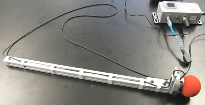
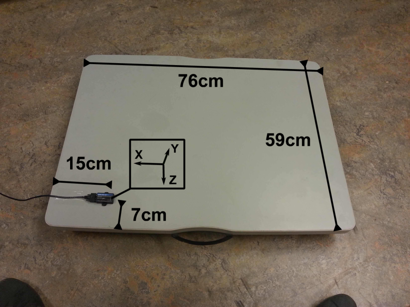
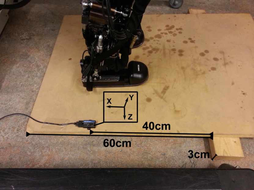
For our experiments we use different tools to generate and measure disturbances on the robot. We built a push stick that has a FTN-Mini 45 force sensor attached. It measures the applied force over time when we push the robot. We conduct experiments where the robot is standing on a rolling platform or a tilting platform that is put on top of a beam. In both scenarios we attached a Microstrain 3DM-GX3-25 IMU (See Figure 3) to the plate that the robot is standing on in order to measure linear acceleration and angular velocities of the platform when a disturbance is applied. These sensors are connected to the controlling computer together with the robot sensors, which allows for easy synchronization of the readings. We use real-time ethernet for the force sensor and real-time USB for the IMU.
5 Experiments
We formulated balancing and motion tracking tasks using the algorithm
discussed in Section 2 together with the
momentum controller discussed in Section 3 and
evaluated them on the Sarcos Humanoid described in
Section 4. The performance of the
controller was evaluated in different scenarios: balancing experiments
and a tracking task in single and double support. A summary of the
experiments is shown in the attached movie 444The movie is also
available on
www.youtube.com/ watch?v=jMj3Uv2Q8Xg
.
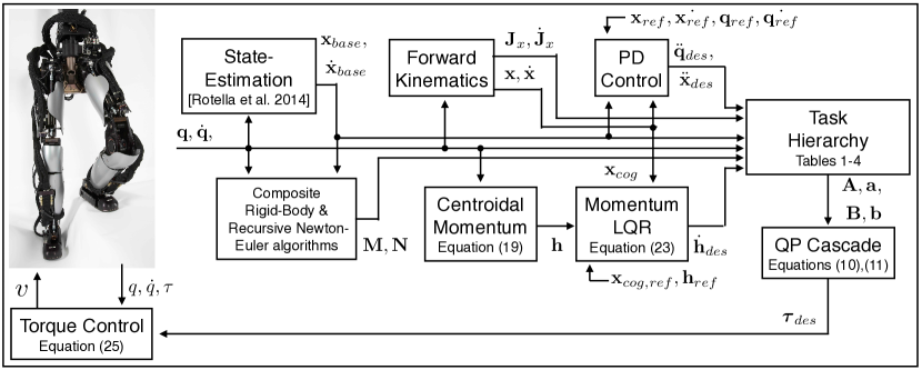
For all the experiments, we run the hierarchical inverse dynamics
controller as a feedback controller. The desired torque commands
computed by the controller are directly sent to the robot. We do not
use any joint PD controller for stabilization (i.e. feedback control
is only done in task space). A diagram visualizing the flow of control
variables is presented in Figure 4.
5.1 Processing Time
The computation time of the solver mainly depends on a) the number of DoFs of the robot b) the number of contact constraints and c) the composed tasks. All experiments were performed on an Intel Core i7-2600 CPU with a 3.40GHz processor. Subsequent QPs (cf. Section 2.2) were solved with an implementation of the Goldfarb-Idnani dual-method Goldfarb:1983ik using the Eigen matrix library. In the real robot experiments we use the 14 DoF lower part of a humanoid to perform several tasks in a 1 kHz control loop. In the following, however, we construct a more complex stepping task in simulation for the full 25 DoF robot. The goal is to a) evaluate the speedup from the simplification proposed in Section 2.3 and b) give an intuition on how the method scales with the complexity of the robot.
| Rank | Nr. of eq/ineq constraints | Constraint/Task |
|---|---|---|
| 1 | 25 eq | Equation (12) (not required for simplified problem) |
| eq | Newton Euler Equation (13) | |
| ineq | torque limits | |
| 2 | eq | Contact constraints, Eq. (2) |
| ineq | Center of Pressure, Sec. 2.1 | |
| ineq | Friction cone, Sec. 2.1 | |
| ineq | joint acceleration limits, Sec. 2.1 | |
| 3 | eq | PD control on CoG |
| PD control on swing foot | ||
| 4 | eq | PD control on posture |
| 5 | eq | regularizer on GRFs |
| DoFs: 25 | max. time: 5 ms / 3 ms \bigstrut[t] |
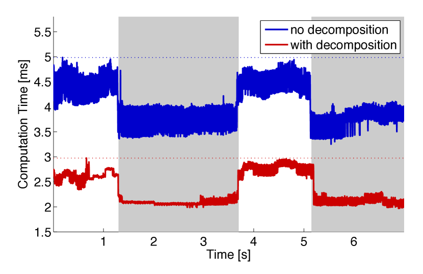
We summarized in Table 1 the hierarchy that is used in simulation. The highest two priorities satisfy hardware limitations and dynamic constraints, the third priority task tracks a predefined center of gravity and swing foot motion and the remaining priorities resolve redundancies on motion and forces. The problem size changes depending on the number of contacts ( in double support and in single support). The proposed decomposition removed 25 equality constraints and 25 optimization variables. We measured the computation time of both versions of the hierarchical solver, one with the full EoM and one with the proposed reduction as plotted in Figure 5. Looking at the worst case (as this is significant for execution in a time critical control loop) we can reduce computation time by 40%. In our experiments with a 14 DoF robot, this speedup allows us to run a 1 kHz control-loop as we will demonstrate in the following sections. It would not have been possible by using this algorithm without the simplification. Going from a 14 DoF robot to a 25 DoF robot with similar task setup makes the peak computation time rise from 1ms to 3ms. In our speed comparison in Figure 5 one can see that computation time varies with the number of constrained end effectors, which can be problematic if the number of contacts increases too much (e.g. when using both hands and feet).
5.2 Balance Control Experiments
In the first set of experiments on the robot, we were interested in systematically evaluating the balance capabilities of the momentum-based controller with hierarchical inverse dynamics. First, we compare the performance of the balance control when using the LQR design and the PD controller described in Section 3 and then test the performance of the robot when balancing on a rolling platform and a balancing board.
5.2.1 Specification of the tasks
The specification of the task is summarized in Table 2 together with the maximum running time for one control cycle. The physical constraints are put in the highest priority. In the second priority, we put kinematic contact constraints, acceleration limits and constraints on reaction forces, i.e. CoP boundaries and friction cones with a higher weight on CoPs. In the third hierarchy level, we express our desired closed loop-dynamics on the momentum together with a PD controller on the posture and ground reaction force regularization. Here, we prefer to have the momentum control together with the posture control on the same level, since the kinematic contact constraints (2nd priority) lock 12 DoFs and the momentum control another 6 DoFs. Given that we only have 20 DoFs (including 6 for the floating base), we are left with too few DoFs to keep a good posture. In our experience this allowed the robot to keep a better looking posture given the limited redundancy available.
We did not carefully tune the weights between the tasks in the same priority level but merely selected an order of magnitude by choosing among 4 different weights for all tasks, or . If not stated otherwise, we chose gains to be diagonal matrices in all of our tasks except the momentum control. We put a higher weight on the momentum control since balancing is our main objective and gave less weight to posture control and regularization of ground reaction torques.
| Rank | Nr. of eq/ineq constraints | Constraint/Task |
|---|---|---|
| 1 | eq | Newton Euler Equation (13) |
| ineq | torque limits | |
| 2 | eq | Contact constraints, Eq. (2) |
| ineq | Center of Presure, Sec. 2.1 | |
| ineq | Friction cone, Sec. 2.1 | |
| ineq | joint acceleration limits, Sec. 2.1 | |
| 3 | eq | momentum control, Eqs. (28) or (3.2) |
| eq | PD control on posture | |
| eq | regularizer on GRFs | |
| DoFs: 14 | max. time: 0.9 ms \bigstrut[t] |
5.2.2 Comparison of momentum controllers
| PD Control | LQR | |||||||||||||
|---|---|---|---|---|---|---|---|---|---|---|---|---|---|---|
| Above Hip Joint | At Hip Joint | Above Hip Joint | At Hip Joint | |||||||||||
| F | R | B | L | F | R | L | F | R | B | L | F | R | L | |
| Peak Force [N] | 233 | 108 | 103 | 80 | 217 | 207 | 202 | 244 | 179 | 107 | 114 | 293 | 223 | 118 |
| Impulse [Ns] | 7.9 | 4.7 | 5.1 | 3.9 | 9.1 | 9.0 | 6.9 | 6.9 | 6.8 | 6.2 | 4.7 | 9.5 | 8.6 | 4.3 |
| max. CoG Error [cm] | 4.6 | 3.5 | 3.4 | 2.8 | 5.0 | 4.3 | 2.8 | 3.4 | 2.8 | 2.7 | 1.8 | 3.3 | 3.0 | 1.5 |
| max. Lin. Mom. [Nm] | 22.6 | 10.2 | 15.8 | 6.9 | 13.1 | 7.9 | 9.3 | 19.8 | 13.6 | 16.3 | 9.1 | 14.4 | 9.2 | 9.5 |
| max. Ang. Mom. [Nms] | 4.1 | 1.9 | 2.2 | 1.5 | 2.4 | 0.9 | 0.7 | 3.7 | 2.5 | 2.1 | 2.0 | 2.8 | 1.1 | 2.0 |
In this experiment we pushed the robot impulsively with our push-stick at various contact points with different force directions. The robot was pushed at 4 points on the torso above the hip (from the front, right, back and left) and at 3 points at hip level (from the front, right and left) as can be seen in the attached video. The electronics of the robot are attached at the back part of the hip which is why we did not push it at that point. At each of the 7 points we applied 4 pushes of increasing impact up to peak forces of 290 N and impulses of 9.5 Ns, which is on the upper scale of pushes in related work Ott:2011uj ; Mason:2014 ; Pratt:2012ug . This episode of experiments is executed with both variations of momentum control discussed in Section 3: PD control with diagonal gain matrices and with optimal gains from LQR design. We put a reasonable amount of effort into finding parameters for both controllers in order to be able to compare them and in both cases we tried to find parameters that would lead to fast damping of momentum, with a slight preference for damping linear momentum to ensure that the CoG was tracked properly. Our resulting LQR performance cost was
| (30) |
with . For both momentum control tasks, the robot was able to withstand impacts with high peak forces and strong impulses without falling. For every push, the change in momentum was damped out quickly and the CoG was tracked after an initial disturbance. While it is difficult to compare the performance of the controllers with other existing state-of-the-art algorithms because very little quantitative data is available and performance can drastically change across robots, it seems that both controllers perform at least as well as, if not better than, other approaches for which data is available Ott:2011uj ; Mason:2014 ; Pratt:2012ug . Indeed, the robot was able to absorb impact up to peak forces of 290 N and impulses of 9.5 Ns. We summarized the information for the strongest pushes in each direction in Table 3 as a reference.
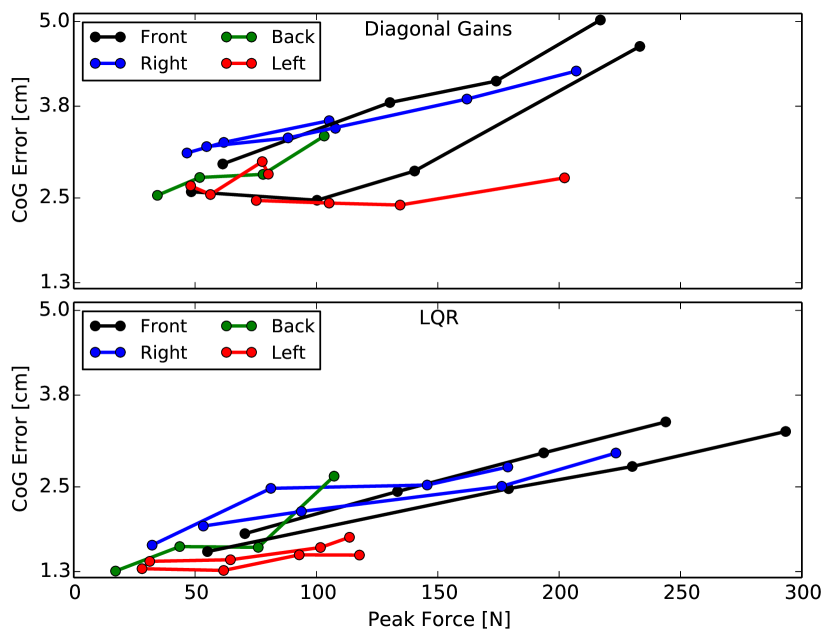
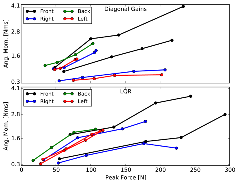
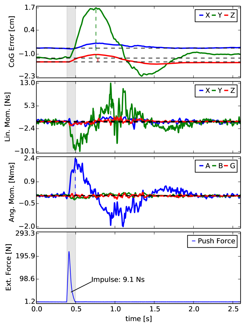
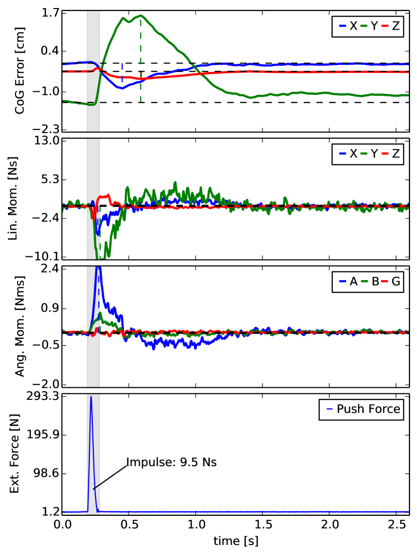
In Figure 6 we systematically plotted the measured peak forces against the maximum deviation of the CoG and angular momentum for both controllers in order to see the typical behavior of the robot. The impulses are not plotted as they were proportional to the peak forces in all our experiments. The maximum error for both angular momentum and CoG tended to be proportional to the peak force for all experiments. We notice from the figure that for both momentum controllers we get similar maximum deviations in angular momentum. However, with the LQR gains we see a significant improvement in recovering the CoG. From Figure 7 we also see how the LQR controller recovers quicker although the robot was pushed harder than with the controller using diagonal gain matrices.
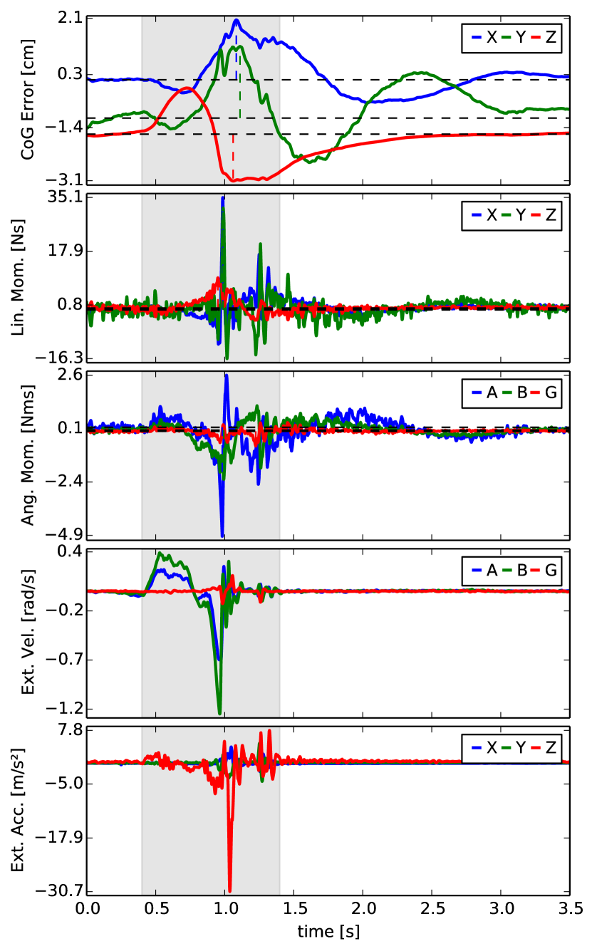
Figure 7 shows a typical response for both controllers where we plotted the impact force together with the CoG tracking error and the momentum. We notice that in both cases the disturbance is damped quickly. We notice that although the peak force is higher for the LQR controller, the response is better behaved than for the PD controller and the momentum is damped faster.
While it is always difficult to ensure that a better set of parameters couldn’t be found for the PD controller, this result suggests that the LQR design performs better than the PD controller. Moreover, the LQR design is much simpler to tune because the design of a performance cost has a more intuitive meaning than PD gains and it can capture the coupling between linear and angular momentum. The other advantage of the LQR design is that once the cost function is fixed, new gains can be computed for various poses and desired momentum behaviors automatically without manual re-tuning. This aspect was very helpful for the contact switching and single support task that we present in the following section.
The balance controller that is implemented does not rely on co-planar feet and is able to produce very compliant behaviors. When we pushed the robot with a constant force at various parts, it stayed in balance and adapted its posture in a compliant manner. We also tested the controller when the feet were not co-planar, but one foot was put on top of a block. These behaviors can be seen in the attached movie.
5.2.3 Balancing on moving platforms
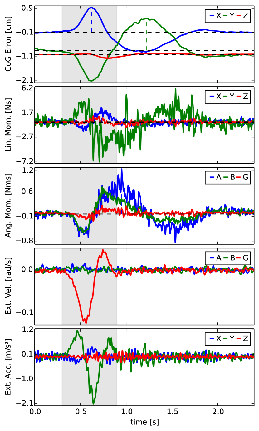
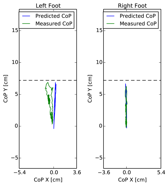
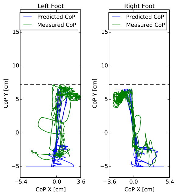
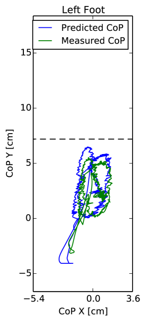
For our next experiment, we put the biped on a rolling platform and rotated and moved it with a rather fast change of directions. A typical behavior of the robot is plotted in Figure 8. The angular velocity and linear acceleration measured from the IMU that we attached to the rolling platform are plotted together with the CoG tracking error and momentum. Although the CoG is moving away from its desired position when the platform is moving around, it remained bounded, the momentum was damped out and the robot kept standing and recovered CoG tracking. The stationary feet indicated that forces were applied that were consistent with our CoP boundaries. We notice from the figure that the CoPs, as they were predicted from the dynamics model, are approximately correct. However, one can expect that a higher precision might be needed to achieve dynamic motions which could be achieved with an inertial parameters estimation procedure Mistry:2009dh .
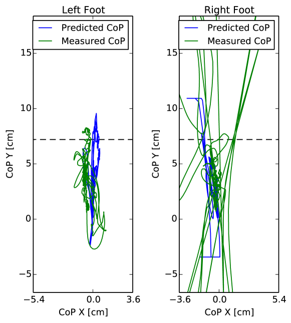
In an additional scenario, the biped was standing on a balancing board. We ran the experiment with two configurations for the robot: in one case the robot is standing such that the board motion happens in the sagittal plane and in the other case the motion happens in the lateral plane. In this case, the slope was varied in a range of elevating the robot up to 6.9 cm. Even for quite rapid changes in the slope, the feet remained flat on the ground. Compared to the push experiment the CoPs were moving in a wider range, but still remained in the interior of the foot soles with a margin. In this case, we notice a discrepancy in the predicted contact forces and the real ones, making the case for the need for a better dynamics model. Eventually, we dropped the robot from the maximum height (Figure 9), such that the feet bounced off the ground at impact and tilted for a moment as can bee seen in the video. Yet, the robot recovered and was still able to balance. We notice in the figure that in this case, the measured CoP of the foot that was lifted drastically differs from the predicted ones. We also note that the predicted CoPs reach their admissible boundary as is seen from the flat horizontal lines.
When we increased the pushes on the robot, eventually the momentum could not be damped out fast enough anymore and the robot reached a situation where the optimization could not find solutions that would balance the robot anymore (i.e. the slack variable associated to the desired momentum becomes very high) and the biped fell. In these cases the constraint that the feet have to be stationary was too restrictive. A higher level controller that takes into account stepping (e.g. Pratt:2012ug ; Urata:2012fb ) becomes necessary to increase the stability margin.
5.3 Tracking Experiments in Double Support
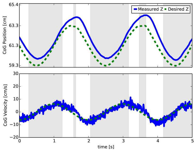
In the next experiment the robot is performing a squatting like motion. We keep the same task hierarchy as in the balance experiments (see Table 2) and make the CoG track sine curves of 0.3 Hz and 0.5 Hz. The CoG is moving with an amplitude of 2 cm in the forward direction and an amplitude of 3 cm in the vertical direction. The results can be seen in the attached video.
In order to demonstrate the utility of the hierarchy, we setup a squatting experiment such that CoP constraints would be activated during the motion. We show the result of this experiment in Figure 10. We notice that the CoP constraints are active in most parts of the experiments. This constraint prevents the feet from tilting and the robot stays stable. We also notice that the real CoPs follow the predicted ones relatively well and stay inside the support polygon. As a consequence, the tracking of the CoG, which is in a lower priority, is not ideal but still achieves a reasonable performance. CoG velocity tracking is still achieved reasonably well. We note that the discrete activation/deactivation of the constraint is not directly visible on the CoG motion behavior.
This experiment illustrates the importance of hierarchies. By solving a QP without a hierarchy, there would be two possibilities, either the CoP constraint is set as a hard constraint of the optimization problem and there is no guarantees that a solution to the problem exists or it is put in the cost function with the CoG task and the solution is necessarily a trade-off between contact constraints and motion tasks. Exploiting a hierarchical setup, we are guaranteed to find a solution to the optimization problem and at the same time we are guaranteed that the CoG tracking task does not interfere with the CoP constraint.
5.4 Single Support Experiments
The experiments in the previous sections were done while the robot remained in double support. The goal of this experiment is to show that the controller can handle more complicated tasks involving contact switching and that the robot is able to balance on a single foot in face of disturbances. Further, we evaluate all capabilities in a single task: contact switching, push rejection in single support and tracking a leg motion.
First the robot moves from a double support position to a single support position where the swing foot is lifted 10 cm above the ground while balancing. This motion consists of 3 phases. First, the robot moves its CoG towards the center of the stance foot. Then an unloading phase occurs during which the contact force regularization enforces a zero contact force to guarantee a continuous transition when the double support constraint is removed. In the final phase, a task controlling the motion of the swing foot is added to the hierarchy. Our contact switching strategy is simple but guarantees that continuous control commands were sent to the robot. For more complicated tasks, such guarantees can always be met by using automatic task transitions such as in jarquin:humanoids:2013 . The composition of hierarchies is summarized in Table 4. Concerning computation time, the controller computes a solution in average well below 1ms but a maximum at 1.05ms is reached a few times during the unloading phase due to many constraints becoming active at the same time.
Once in single support, we pushed the robot to verify that it is balancing. Impacts were applied with peak forces up to 150 N and impulses between 4.5 Ns and 5.8 Ns. We saw a quick recovery of the CoG while the CoPs stayed bounded. In order to control the foot we used Cartesian position control (i.e. the swing foot task consists of a PD controller for the foot position in Cartesian space).
| Rank | Nr. of eq/ineq constraints | Constraint/Task |
| 1 | eq | Newton Euler Equation (13) |
| ineq | torque limits | |
| 2 | ineq | Center of Pressure, Sec. 2.1 |
| ineq | Friction cone, Sec. 2.1 | |
| ineq | joint acceleration limits, Sec. 2.1 | |
| 3 | eq. | Linear and angular momen- |
| tum control | ||
| eq. | Contact constraints, Eq. (2) | |
| eq. | Foot motion (swing) | |
| eq. | PD control on posture | |
| 4 | eq. | regularizer on GRFs |
| DoFs: 14 | max. time: 1.05 ms \bigstrut[t] |
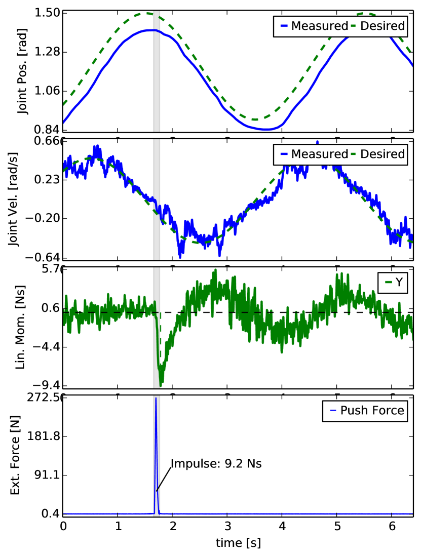
We repeat the experiment where the robot, once it is standing on one leg, swings its leg up and down tracking 0.25 Hz sine curves on the hip and knee flexion/extension joints (as can be seen in Figure 11). In this case, we swap the Cartesian foot control for a desired trajectory of the hip and knee in joint space (i.e. a task that consists of time-varying positions for both joints). Indeed, while in simulation Cartesian tracking is perfect, on the real robot the tracking performance of the Cartesian task of the swing foot is not satisfactory when moving at higher speeds and amplitudes. We suspect that several reasons can explain the problem. One of the reasons seems to be due to the amount of noise present in the position sensors such that it is difficult to increase the position gains while still being able to damp the system. Since the feedback loop is closed around the foot position, which is estimated through forward kinematics, its velocity estimation seems to suffer from the cumulative noise of all the sensors. In this case, a direct joint control suffers less from that problem. Another problem could come from an insufficiently accurate model of the swing leg dynamics where unmodeled dynamics could become more dominant.
While the robot is performing the task, it is pushed strongly at the hip from the front as can be seen in the video. The joint tracking together with the linear momentum and the push force are shown in Figure 11. A spike in momentum can be seen at the moment of impact, but is damped and remains bounded. During the push, the CoP constraint is activated when the CoP comes close to the heel. Thanks to the inequality constraint, the foot does not start tilting and the robot can recover from the push. What is remarkable is that the swing leg tracking is barely affected although the push is comparable to the strongest impacts we applied in double support. It is worth mentioning again that the foot size of the robot is rather small compared to other humanoids.
6 Discussion
In the following we discuss the results we presented and how they relate to other approaches.
6.1 Task design and hierarchies
In our experiments, we exploit hierarchical separation of physical constraints and tasks, such as the robot dynamics and reaction force constraints and balancing tasks. This is guaranteed to always find a feasible solution while generating physically consistent solutions and generating admissible task dynamics as close as possible to the desired ones. As we have shown in the experiments, this is important to keep balance in cases when reaction force constraints conflict with lower priority tasks. Here, hierarchies can guarantee that performance in balancing is traded off, but the physical consistency of the solution is always guaranteed. Note that with a QP formulation this would not be possible.
From our experience, we prefer to keep posture tracking task and momentum control in the same priority and adapt importance by weights. It seems that the 14 DoFs of our robot are too limiting and do not leave enough freedom when posture control is put in a separate rank. Using a full humanoid with arms will increase the flexibility of the robot and allow for more hierarchy levels. We expect to have, for example, manipulation tasks in a higher priority than balancing tasks.
As mentioned in the experiment description we used only a small set of weights for our tasks. This already gives us a balancing performance that is at least as good as related work if not better. Better performance can be achieved by adjusting parameters and hierarchical setup more specific to tasks of interest herzog:2014b . It is important to note that in both contributions we do not use joint PD stabilization, but verify that the performance is solely the effect of the hierarchical inverse dynamics controller.
6.2 Relation to other balancing approaches
The balance control strategy used in this paper is similar to the formulation of the momentum-based controller presented by Lee and Goswami Lee:2012hb ; Lee:2010em . Our formulation has the great advantage of solving a single optimization problem instead of several ones and can therefore guarantee that the control law will be consistent with all the constraints (joint limits, accelerations, torque saturation, CoP limits and contact force limitations). As we have seen in the experiments, consistency with inequality constraints can be very important to improve robustness. Furthermore, we search over the full set of possible solutions and thus we are guaranteed to find the optimum, where Lee:2012hb ; Lee:2010em optimize over sub-parts of the variables sequentially. It is also different from the work of Kajita:2003gj because we explicitly take into account contact forces in the optimization and not purely kinematics, which allows us to optimize the internal forces created by the contacts.
The balance controller is related to the work of Stephens:2010vu . In Stephens:2010vu , the authors write the whole optimization procedure using Equation (1) with constraints similar to the ones we use. However, with the optimization problem being complicated, they actually solve a simpler problem where the contact forces are first determined and then desired accelerations and torques are computed through a least-square solution. From that point of view, torque saturation and limits on accelerations are not accounted for. In our experiments, no tradeoff is necessary and we solve for all the constraints exactly. Further, the capability of strict task prioritization makes the design of more complicated tasks like balancing on one foot easier. Also, separating the EoM from kinematic contact constraints allows to keep solutions consistent with the dynamics even in postures where the feet cannot be kept stationary.
We have also shown in the paper that the use of a LQR design for the momentum task can simplify the controller design and improve robot performance by taking into account the coupling between linear and angular momentum. This design was particularly useful for the contact switching and single support task. Indeed, using the PD control approach, it was not possible to use the same gains in double or single support to regulate the CoG. With the LQR design, the gains for the momentum control were automatically computed using the same cost function and therefore no specific gain tuning was needed.
6.3 Relations to other hierarchical inverse dynamics solvers
The implemented QP cascade is a combination of the two
algorithms Kanoun:2011ey ; deLasa:2010hf .
We use a surjective Nullspace map (cf.
Equation 8), similar to deLasa:2010hf .
However, in deLasa:2010hf inequality constraints are included
only in the first priority, i.e.
. Instead, the proposed method
allows for prioritization among inequality constraints as it was done
in Kanoun:2011ey . This variant of QP cascades combines the
benefits of both algorithms. On the one hand variables are eliminated
from one QP to the other, resulting in faster solvable QPs. On the
other hand, it allows for prioritization of inequality constraints,
which we exploit e.g. to give more
importance to hardware limitations than to contact constraints.
Although fast enough for our experiments on the lower part of our
humanoid robot, the speed comparison in
Section 5.1 shows that a more efficient
algorithm is required when we run feedback control on the full 25 DoF
robot.
A method that is tailored to solve inequality constrained hierarchical
tasks was derived in Escande:2014en . With an active set method
dedicated to solve prioritized inequality constraints, it can
outperform QP cascades in terms of speed.
The QP cascade used in this algorithm trades off computational
efficiency to a simpler implementation, where the handling of
inequality constraints is passed on to an off-the shelf QP solver. As
the focus of this paper was the experimental evaluation of the problem
formulation, a QP cascade with the employed modifications was
sufficiently fast and relatively easy to implement.
Another practical advantage of QP cascades is the easily implemented
regularization term in Equation (5), which increases
numerical robustness in face of task singularities as discussed
in Kanoun:2011ey .
The approach of Escande:2014en might also be interesting
because it would directly allow the use of warm-start techniques to
speed up the computations. Warm starting the optimizer should
significantly improve computation time since during most tasks the
active set does not change much from one control step to the other.
Any inverse dynamics approach using either QP
cascades Mansard:2012gy ,Saab:2013vr or Hierarchical QP
algorithm might profit from the decomposition proposed in
Section 2.3, as it is not required to compute an SVD of
the full equations of motion, but only of the last six rows.
7 Conclusion
In this paper, we have presented experimental results using a hierarchical inverse dynamics controller. A variant of cascades of QPs was presented and implemented in a 1 kHz feedback-control loop. We used LQR to formulate momentum controllers for balancing and tracking tasks. Our main focus then was the experimental evaluation of the control framework on a torque controlled humanoid robot. In a series of experiments, we evaluated systematically the balancing and tracking capabilities of the robot. The humanoid showed a robust performance in single and double support and was able to recover from pushes and other disturbances. Our results suggest that the use of complete dynamic models and hierarchies of tasks for feedback control is a feasible approach, despite the model inaccuracies and computational complexity. For future work, we would like to integrate higher level planners to compose more complex tasks such as walking.
Acknowledgements.
We would like to thank Ambarish Goswami and Seungkook Yun for hosting us at the Honda Research Institute for one week and for their precious help in understanding the original momentum-based controller. We would also like to thank Ambarish Goswami and Sung-Hee Lee for giving us an early access to their publication. We are also grateful to Daniel Kappler for helping us with the videos. Last, but not least, we would like to thank the anonymous reviewers for their very valuable comments that helped improve the final version of the paper.This research was supported in part by National Science Foundation grants IIS-1205249, IIS-1017134, CNS-0960061, EECS-0926052, the DARPA program on Autonomous Robotic Manipulation, the Office of Naval Research, the Okawa Foundation, and the Max-Planck-Society. Any opinions, findings, and conclusions or recommendations expressed in this material are those of the author(s) and do not necessarily reflect the views of the funding organizations.
References
- (1) Ayusawa, K., Venture, G., Nakamura, Y.: Identifiability and identification of inertial parameters using the underactuated base-link dynamics for legged multibody systems. The International Journal of Robotics Research 33, 446–468 (2014)
- (2) Bloesch, M., Hutter, M., Hoepflinger, M.H., Remy, C.D., Gehring, C., Siegwart, R.: State estimation for legged robots-consistent fusion of leg kinematics and IMU. In: Robotics: Science and Systems (R:SS) (2012)
- (3) Boaventura, T., Focchi, M., Frigerio, M., Buchli, J., Semini, C., Medrano-Cerda, G.A., Caldwell, D.: On the role of load motion compensation in high-performance force control. In: IEEE/RSJ Intl Conf on Intelligent Robots and Systems (2012)
- (4) Boaventura, T., Semini, C., Buchli, J., Frigerio, M., Focchi, M., Caldwell, D.: Dynamic Torque Control of a Hydraulic Quadruped Robot. In: IEEE Intl Conf on Robotics and Automation (2012)
- (5) Cheng, G., Sang-Ho, H., Ude, A., Morimoto, J., Hale, J.G., Hart, J., Nakanishi, J., Bentivegna, D., Hodgins, J., Atkeson, C., Mistry, M., Schaal, S., Kawato, M.: CB: Exploring Neuroscience with a Humanoid Research Platform. In: IEEE Intl Conf on Robotics and Automation (2008)
- (6) Escande, A., Mansard, N., Wieber, P.B.: Hierarchical quadratic programming: Fast online humanoid-robot motion generation. The International Journal of Robotics Research 33(7), 1006–1028 (2014)
- (7) Faraji, S., Pouya, S., Atkeson, C., Ijspeert, A.: Versatile and robust 3d walking with a simulated humanoid robot (atlas): a model predictive control approach. In: IEEE International Conference on Robotics and Automation (2014)
- (8) Feng, S., Xinjilefu, X., Huang, W., Atkeson, C.: 3d walking based on online optimization. In: IEEE International Conference on Robotics and Automation (2014)
- (9) Goldfarb, D., Idnani, A.: A numerically stable dual method for solving strictly convex quadratic programs. Mathematical programming 27(1), 1–33 (1983)
- (10) Herzog, A., Righetti, L., Grimminger, F., Pastor, P., Schaal, S.: Momentum-based balance control for torque-controlled humanoids. http://arxiv.org/abs/1305.2042v1 (2013)
- (11) Herzog, A., Righetti, L., Grimminger, F., Pastor, P., Schaal, S.: Balancing experiments on a torque-controlled humanoid with hierarchical inverse dynamics. In: IEEE/RSJ Intl Conf on Intelligent Robots and Systems (2014)
- (12) Hutter, M., Hoepflinger, M.A., Gehring, C., Bloesch, M., Remy, C.D., Siegwart, R.: Hybrid Operational Space Control for Compliant Legged Systems. In: Robotics: Science and Systems (R:SS) (2012)
- (13) Hyon, S.H., Hale, J.G., Cheng, G.: Full-Body Compliant Human–Humanoid Interaction: Balancing in the Presence of Unknown External Forces. IEEE Transactions on Robotics 23(5), 884–898 (2007)
- (14) Jarquin, G., Escande, A., Arechavaleta, G., Moulard, T., Yoshida, E., Parra-Vega, V.: Real-time smooth task transitions for hierarchical inverse kinematics. In: IEEE-RAS Intl Conf on Humanoid Robots (2013)
- (15) Kajita, S., Kanehiro, F., Kaneko, K., Fujiwara, K., Harada, K., Yokoi, K., Hirukawa, H.: Resolved momentum control: humanoid motion planning based on the linear and angular momentum. In: IEEE/RSJ Intl Conf on Intelligent Robots and Systems (2003)
- (16) Kalakrishnan, M., Buchli, J., Pastor, P., Mistry, M., Schaal, S.: Learning, Planning, and Control for Quadruped Locomotion over Challenging Terrain. The Intl Journal of Robotics Research 30(2), 236–258 (2011)
- (17) Kanoun, O., Lamiraux, F., Wieber, P.B.: Kinematic Control of Redundant Manipulators: Generalizing the Task-Priority Framework to Inequality Task. IEEE Transactions on Robotics 27(4), 785–792 (2011)
- (18) Kuindersma, S., Permenter, F., Tedrake, R.: An efficiently solvable quadratic program for stabilizing dynamic locomotion. In: IEEE International Conference on Robotics and Automation (2014)
- (19) de Lasa, M., Mordatch, I., Hertzmann, A.: Feature-Based Locomotion Controllers. ACM Transactions on Graphics 29(3) (2010)
- (20) Lee, S.H., Goswami, A.: Ground reaction force control at each foot: A momentum-based humanoid balance controller for non-level and non-stationary ground. In: IEEE/RSJ Intl Conf on Intelligent Robots and Systems, pp. 3157–3162 (2010)
- (21) Lee, S.H., Goswami, A.: A momentum-based balance controller for humanoid robots on non-level and non-stationary ground. Autonomous Robots 33, 399–414 (2012)
- (22) Mansard, N.: A dedicated solver for fast operational-space inverse dynamics. In: IEEE Intl Conf on Robotics and Automation (2012)
- (23) Mason, S., Righetti, L., Schaal, S.: Full dynamics lqr control of a humanoid robot: An experimental study on balancing and squatting. In: IEEE-RAS Intl Conf on Humanoid Robots (2014)
- (24) Mistry, M., Schaal, S., Yamane, K.: Inertial Parameter Estimation of Floating Base Humanoid Systems using Partial Force Sensing. In: IEEE-RAS Intl Conf on Humanoid Robots (2009)
- (25) Moro, F., Gienger, M., Goswami, A., Tsagarakis, N., Caldwell, D.: An attractor-based whole-body motion control (wbmc) system for humanoid robots. In: IEEE-RAS International Conference on Humanoid Robots (2013)
- (26) Nakamura, Y., Hanafusa, H., Yoshikawa, T.: Task-priority based redundancy control of robot manipulators. The International Journal of Robotics Research 6, 3–15 (1987)
- (27) Orin, D.E., Goswami, A.: Centroidal Momentum Matrix of a humanoid robot: Structure and Properties. In: IEEE/RSJ Intl Conf on Intelligent Robots and Systems (2008)
- (28) Ott, C., Roa, M.A., Hirzinger, G.: Posture and balance control for biped robots based on contact force optimization. In: IEEE-RAS Intl Conf on Humanoid Robots (2011)
- (29) Pratt, J., Koolen, T., De Boer, T., Rebula, J., Cotton, S., Carff, J., Johnson, M., Neuhaus, P.: Capturability-based analysis and control of legged locomotion, Part 2: Application to M2V2, a lower-body humanoid. The Intl Journal of Robotics Research 31(10) (2012)
- (30) Righetti, L., Buchli, J., Mistry, M., Kalakrishnan, M., Schaal, S.: Optimal distribution of contact forces with inverse-dynamics control. The Intl Journal of Robotics Research 32(3), 280–298 (2013)
- (31) Righetti, L., Buchli, J., Mistry, M., Schaal, S.: Control of legged robots with optimal distribution of contact forces. In: 2011 11th IEEE-RAS International Conference on Humanoid Robots, pp. 318–324 (2011)
- (32) Rotella, N., Bloesch, M., Righetti, L., Schaal, S.: State Estimation for a Humanoid Robot. In: IEEE/RSJ Intl Conf on Intelligent Robots and Systems (2014)
- (33) Saab, L., Ramos, O., Mansard, N., Soueres, P., Fourquet, J.Y.: Dynamic Whole-Body Motion Generation Under Rigid Contacts and Other Unilateral Constraints. In: IEEE Transactions on Robotics (2013)
- (34) Salini, J., Padois, V., Bidaud, P.: Synthesis of Complex Humanoid Whole-Body Behavior: A Focus on Sequencing and Tasks Transitions. In: IEEE Intl Conf on Robotics and Automation (2011)
- (35) Sentis, L., Khatib, O.: Synthesis of whole-body behaviors through hierarchical control of behavioral primitives. International Journal of Humanoid Robotics pp. 505–518 (2005)
- (36) Stephens, B.J., Atkeson, C.G.: Dynamic Balance Force Control for compliant humanoid robots. In: IEEE/RSJ Intl Conf on Intelligent Robots and Systems (2010)
- (37) Urata, J., Nshiwaki, K., Nakanishi, Y., Okada, K., Kagami, S., Inaba, M.: Online Walking Pattern Generation for Push Recovery and Minimum Delay to Commanded Change of Direction and Speed. In: IEEE/RSJ Intl Conf on Intelligent Robots and Systems (2012)
- (38) Vaillant, J., Kheddar, A., Audren, H., Keith, F., Brossette, S., Kaneko, K., Morisawa, M., Yoshida, E., Kanehiro, F.: Vertical ladder climbing by the HRP-2 humanoid robot. In: Humanoid Robots (Humanoids), 2014 14th IEEE-RAS International Conference on, pp. 671–676 (2014)
- (39) Wensing, P., Orin, D.: Generation of dynamic humanoid behaviors through task-space control with conic optimization. In: 2013 IEEE International Conference on Robotics and Automation (2013)
- (40) Wieber, P.: Holonomy and nonholonomy in the dynamics of articulated motion. Fast motions in biomechanics and robotics pp. 411–425 (2006)
![[Uncaptioned image]](/html/1410.7284/assets/herzog.jpg)
Alexander Herzog is a PhD student at the Max Planck Institute for
Intelligent Systems, Tübingen. He
studied Computer-Science at the Karlsruhe Institute
of Technology, in Germany. Alexander visited the Computational Learning and Motor Control Lab (University of Southern
California) in 2011,
where he worked on the problem of grasp planning for his diploma
thesis. After receiving his Diploma in the same year, he joined
the Autonomous Motion Laboratory at the Max-Planck Institute for
Intelligent Systems in 2012. His research interests include contact
interaction in whole-body control and grasping for humanoids.
![[Uncaptioned image]](/html/1410.7284/assets/rotella.png)
Nicholas Rotella studied Mechanical Engineering at The Cooper
Union for the Advancement of Science and Art in New York, NY from 2008
to 2012, after which he joined the CLMC lab at USC to pursue a PhD in
Computer Science. He passed his PhD screening process and received his
Masters degree in Computer Science from USC in 2014 and continues to
work towards his PhD. His research interests include optimal
estimation and control for legged robotic systems, controlling contact
interactions for locomotion and manipulation, trajectory optimization
and planning of complex motor control tasks.
![[Uncaptioned image]](/html/1410.7284/assets/mason.jpg)
Sean Mason received the B.S. and M.S. degrees in mechanical
engineering from Drexel University in Philadelphia, PA in 2012. In
2015, he received the M.S. degree and is currently working towards the
Ph.D. degree in Computer Science at the University of Southern
California. His research interests include optimal control, biped
locomotion, and whole-body control frameworks for torque controlled
robots.
![[Uncaptioned image]](/html/1410.7284/assets/grimminger.jpg)
Felix Grimminger is a mechatronics engineer working in Stefan Schaal’s Autonomous Motion Department at the Max-Planck-Institute for Intelligent Systems in Tübingen, Germany.
Before joining the Autonomous Motion Lab in 2013 he worked for Boston
Dynamics on the BigDog project and on several different robotic
projects at the German Research Center for Artificial Intelligence in
Bremen, Germany. He is especially interested in mechanical design,
series elastic actuation and highly dynamic legged robots.
![[Uncaptioned image]](/html/1410.7284/assets/schaal.jpg)
Stefan Schaal is Professor of Computer Science, Neuroscience, and
Biomedical Engineering at the University of Southern California, and a
Founding Director of the Max-Planck-Insitute for Intelligent Systems
in Tübingen, Germany. He is also an Invited Researcher at the ATR
Computational Neuroscience Laboratory in Japan, where he held an
appointment as Head of the Computational Learning Group during an
international ERATO project, the Kawato Dynamic Brain Project
(ERATO/JST).
Before joining USC, Dr. Schaal was a postdoctoral fellow at the
Department of Brain and Cognitive Sciences and the Artificial Intelligence
Laboratory at MIT, an Invited Researcher at the ATR Human Information Processing
Research Laboratories in Japan, and an Adjunct Assistant Professor at
the Georgia Institute of Technology and at the Department of Kinesiology
of the Pennsylvania State University. Stefan Schaal’s research interests
include topics of statistical and machine learning, neural networks,
computational neuroscience, functional brain imaging, nonlinear dynamics, nonlinear
control theory, and biomimetic robotics. He applies his research to
problems of artificial and biological motor control and motor
learning, focusing on both theoretical investigations and experiments with human
subjects and anthropomorphic robot equipment.
![[Uncaptioned image]](/html/1410.7284/assets/righetti.png)
Ludovic Righetti leads the Movement Generation and Control group at the Max-Planck Institute for Intelligent Systems (Tübingen, Germany) since September 2012. Before, he was a postdoctoral fellow at the Computational Learning and Motor Control Lab (University of Southern California) between March 2009 and August 2012. He studied at the Ecole Polytechnique Fédérale de Lausanne where he received a diploma in Computer Science (eq. MSc) in 2004 and a Doctorate in Science in 2008. His research focuses on the generation and control of movements for autonomous robots, with a special emphasis on legged locomotion and manipulation.