BASELINE LHC MACHINE PARAMETERS AND CONFIGURATION
OF THE 2015 PROTON RUN
Abstract
This paper shows the baseline LHC machine parameters for the 2015 start-up. Many systems have been upgraded during LS1 and in 2015 the LHC will operate at a higher energy than before and with a tighter filling scheme. Therefore, the 2015 commissioning phase risks to be less smooth than in 2012. The proposed starting configuration puts the focus on feasibility rather than peak performance and includes margins for operational uncertainties. Instead, once beam experience and a better machine knowledge has been obtained, a push in and performance can be envisaged. In this paper, the focus is on collimation settings and reach in —other parameters are covered in greater depth by other papers in these proceedings.
1 INTRODUCTION
The first running period of the LHC, Run I [1], was very successful and resulted in important discoveries in physics. In spring 2013, the LHC was shut down for about 2 years, in order to allow consolidation of the superconducting splices in the magnet interconnects, following the incident of 2008. In parallel, numerous other machine systems have been consolidated or upgraded. A common goal of the upgrades is to improve the machine so that it can safely operate closer to its design energy and thus extend the physics discovery potential. For the restart of the LHC in 2015, several challenges can be anticipated, and it is important to carefully define its operational parameters at the start-up in order to maximize the chances of a smooth and successful second running period.
In this paper, we discuss first the general strategy for 2015, which leads up to a proposed choice of starting configuration. Our focus is on collimator settings and reach in , since most other parameters are covered by other papers in these proceedings [2, 3, 4, 5, 6, 7, 8, 9]. We discuss also how the performance can be increased later in the run, when the operational behavior of the machine is better known.
2 strategy for 2015
When the LHC restarts in 2015, it will operate at a higher energy and shorter bunch spacing than in 2012 (6.5 TeV and 25 ns compared to 4 TeV and 50 ns) [2, 3]. These changes imply new major operational and beam physics challenges. Furthermore, the higher beam energy and potentially larger total beam intensities make the LHC beams more dangerous. Fewer protons are needed to cause quenches or damage of sensitive machine components. At the same time, the risk of a known serious failure mode, the asynchronous beam dump, increases at higher energy [10], and a higher rate of UFOs is expected [11]. It is also uncertain how the operational issues encountered in 2012, such as instabilities and beam lifetime drops, will be manifested at 6.5 TeV.
Because of the many uncertainties, the operational behavior of the machine in 2015 is not as well known as in the end of Run I, which means that the beam commissioning risks to be less smooth as in 2012. Therefore, we envisage in the operational strategy for 2015 a careful start of the LHC in a relaxed configuration, which allows larger operational margins. The focus is put on feasibility, stability, and ease of commissioning, and the main priority is not peak performance but rather to establish a running machine at 6.5 TeV and 25 ns. Where possible, it should be avoided to introduce too many new features at once. On the other hand, the starting parameters should also not be overly pessimistic. Therefore, the operational achievements in Run I are used, where possible, to deduce what is likely to work.
The main focus in this paper is to define the machine parameters for the start-up, but we discuss also, at the end of the paper, what changes can be made later in the year. Once sufficient beam experience is gathered through machine development sessions [12] or routine operation, the luminosity performance could be pushed. The ultimate reach in luminosity is hard to predict but we give an overview of the different parameters that can be adjusted.
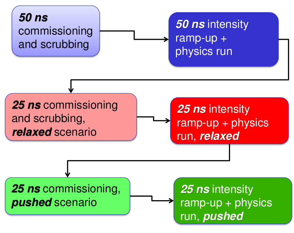
Even though the final goal is to operate at 25 ns, a short initial run will take place at 50 ns. In order to save commissioning time, this run will use the same machine configuration as the 25 ns run. Therefore, we do not discuss in further detail the 50 ns run.
These different stages of the 2015 proton physics period are schematically summarized in Fig. 1. Each physics run has to be preceded by a scrubbing period to mitigate the effects of electron cloud [5] and possibly by additional commissioning.
Further details of the 2015 run can be found in Ref. [4].
3 Beam characteristics
Although the design proton beam energy of the LHC is 7 TeV, the baseline energy for 2015 is 6.5 TeV. The reason is that, in order to reach 7 TeV, it is estimated that an unfeasibly large number of training quenches is needed [13], although this estimate might be adjusted in the future, when more results of powering tests become available [2].
There has been a strong request from the experiments to operate with the design bunch spacing of 25 ns, since it provides potentially higher luminosity and lower pileup [3]. The 25 ns scheme is, however, coupled to several potential complications, for example stronger electron cloud [5] and the need of a larger crossing angle to compensate for the stronger long-range beam-beam effect [14].
The characteristics of the LHC bunches in physics operation are strongly dependent on the beam provided by the injectors. Presently, the injectors can provide two different types of beams: BCMS (batch compression and merging and splittings) and nominal [6]. In both schemes, the achievable bunch intensity is, under optimistic assumptions, up to about , which is slightly higher than the nominal . The BCMS beams have significantly smaller emittances (at LHC injection down to 1.3 m normalized emittance compared to 2.4 m for nominal) but fewer bunches (2544 or 2592 colliding in IR1 and IR5, depending on the number of trains, compared to 2736 for nominal).
Once injected in the LHC, intensity loss and emittance growth are very likely to occur. Using typical numbers from Run I, an intensity loss of about 5% could be expected, which leaves a bunch intensity up to about in collision. The emittance is affected by several physical processes. If only the unavoidable effect from intrabeam scattering (IBS) is accounted for, growths of 20% or 5% have been calculated [15] for BMCS and nominal respectively. However, if the scrubbing runs are not fully successful in mitigating the electron clouds, a much larger emittance growth is likely to occur [5].
Although with a potentially much higher peak luminosity, it is not obvious that BCMS is the better choice, since the very small emittance could have a detrimental effect on the single-beam stability [16]. In addition, the small emittances are more challenging for machine protection [7]. Therefore, the choice between the two beams is still at the time of writing (September 2014) an open question.
In the longitudinal plane, a bunch length of 1.25 ns can be expected at injection and 1.2 ns in collision, for the RF voltages of 6 MV (injection) and 12 MV (collision) [17, 8]. Shorter bunches of nominal length (about 1 ns) could be within reach from the machine side and could be put into operation. Possibly, the increased pileup density can be handled by the experimental detectors [3]. A shorter bunch length would be beneficial for the luminosity since the geometric reduction factor is increased.
4 LHC cycle and optics
Several significant changes to the LHC operational cycle are under study. Examples of such changes are luminosity leveling by dynamically changing during stable beams (in order to reduce the pileup), putting the beams into collision already before the squeeze starts (in order to stabilize the beams in the squeeze using the tune spread introduced by the collisions) [18] or combining the ramp and the squeeze (to make the cycle shorter) [19]. With the philosophy that it should be avoided, where possible, to introduce untested features at the 2015 start-up, these operational improvements are a priori not a part of the start-up baseline, but could instead be introduced at a later stage in the run when more experience has been gained. A detailed account of the nominal cycle is given in Ref. [20].
Two different optics schemes have been under consideration: the nominal optics [21], used in Run I, and the achromatic telescopic squeeze (ATS) [22]. ATS is a promising option that could provide several advantages, but it has also some outstanding points that need further study [23]. Therefore, it has been decided to start with nominal optics, while keeping the possibility to switch to ATS at a later point. Further details are given in Ref. [9].
| Collimators | Relaxed settings () | mm settings kept () | settings kept () |
|---|---|---|---|
| TCP7 | 6.7 | 5.5 | 5.5 |
| TCS7 | 9.9 | 8.0 | 7.5 |
| TCLA7 | 12.5 | 10.6 | 9.5 |
| TCS6 | 10.7 | 9.1 | 8.3 |
| TCDQ6 | 11.2 | 9.6 | 8.8 |
| TCT | 13.2 | 11.5 | 10.7 |
| protected aperture () | 14.8 | 13.4 | 12.3 |
The injection optics for 2015 will thus stay the same as in 2012. At top energy, a new final point of the squeeze has to be decided upon, together with a new crossing angle. This is discussed in detail in the following sections for IR1 and IR5, where is limited by the available aperture. In IR2 and IR8, is instead adjusted to the luminosity that the detectors can handle, and the aperture is less critical. IR2 will therefore stay at the injection value of =10 m with an external half crossing angle of 120 rad, while IR8 will use the same configuration of =3 m as in 2012 and an external half crossing angle of -250 rad. It should be noted though that the crossing angles in IR2 and IR8 are under review by the ABP/HSC section to ensure that beam-beam effects are in the shadow of IR1 and IR5. In all IRs except IR8, a parallel separation of 2 mm will be used at injection, as in 2012. In IR8, the parallel separation has to be increased to 3.5 mm with the addition of a parallel angle of 40 rad [24]. In collision, the 2012 value of the parallel separation is rescaled by the energy and rounded to obtain 0.55 mm at all IRs.
5 Collimator settings
The LHC collimation system [21, 25, 26, 27] influences directly the peak luminosity performance in several ways. Firstly, the cleaning inefficiency (the local losses in a cold element normalized by the total losses on collimators), together with the beam lifetime and the quench limit, define the maximum acceptable intensity. Secondly, when pushing the to smaller values, the -function in the inner triplets increases, meaning that the normalized aperture margin between the central orbit and the mechanical aperture decreases. If this margin becomes too small, the aperture can no longer be fully protected by the collimation system. At what aperture this occurs depends on the collimator settings. The loss in aperture is further enhanced by the fact that a larger crossing angle is needed at smaller in order to keep the same normalized beam-beam separation. The collimators are also the main contribution to the LHC impedance, which is crucial for beam stability.
Different collimator settings have been under consideration for the 2015 start-up and the three main scenarios are shown in Table 1. In terms of cleaning, the relaxed settings are close to the limit of preventing a beam dump at a beam lifetime of 12 minutes and full nominal intensity, even though significant uncertainties exist [28]. Although a detailed verification with final optics is pending at the time of writing, it is expected that the other two types of settings have better cleaning efficiency that should suffice, unless the beam lifetime drops significantly below the 12 minutes specification, or the quench limit would be much worse than expected. Therefore, we do not expect the cleaning inefficiency to be a limiting factor for the total beam intensity.
In order to be on the safe side for the cleaning, but without going to the tighter gaps with the 2 retraction that are more challenging in terms of impedance, Run II will start with the 2012 settings kept in mm (middle column in Table 1). They also have a well-proven long-term stability in terms of preserving the hierarchy under unavoidable drifts of optics and orbit.
The impedance and single-beam stability for the different collimator settings are discussed in Ref. [16]. It is shown that for the nominal, large-emittance beam, all proposed collimator settings should provide sufficient stability with both octupole polarities, while stability could be an issue with the BCMS beams. The two-beam effects and octupole polarities are discussed in detail in Ref. [14].
For machine protection, the settings in Table 1 fulfill the same demands as used during Run I [29, 30] in terms of the IR6 dump protection shadowing the tertiary collimators (TCTs) and the TCTs shadowing the triplets. The margins between different collimator families are calculated based on what was achieved in Run I. If the stability of the optics or orbit correction for post-LS1 would be worse, larger margins are needed. Furthermore, the TCT damage limit in number of protons is lower and the baseline 25 ns filling scheme means that there is a risk to have double the number of bunches within the critical time window during asynchronous dumps when bunches pass the dump kickers and receive intermediate kicks. Therefore, it could be wise to introduce more margins at the start-up, before the machine stability is well known, in order to be sure that the TCTs and aperture are protected. This is especially true at more relaxed values of , where the orbit in mm scales to a larger variation in units of so that larger margins in are needed.
For the calculation of we first investigate the limiting configuration with a protected aperture of 13.4 from Table 1 and then evaluate more relaxed scenarios.
6 Aperture and crossing angle
Given the aperture that is protected by the collimation system, the achievable can be calculated, if also the required aperture as a function of is known. This function depends both on which tolerances are included in the aperture calculation and on the required crossing angle.
The aperture was measured during Run I on several occasions [31, 32, 33, 34, 35, 36, 37], using the circulating beam, and it was found that the results were compatible with a very well aligned machine with very small errors [38]. During the shutdown, all magnets have been realigned, so the alignment should a priori not be worse than at the start of Run I.
For the aperture calculation, we therefore assume that the aperture has not become worse during LS1 and, at this stage, we do not include additional safety margins on orbit or optics. However, we base our calculations on the most pessimistic measurement from 2012. We scale this measured value by and add the change in orbit due to a different crossing angle, in order to estimate the crossing plane aperture at any other configuration. This straightforward, analytic method has proven to give results very close to the MAD-X aperture model [39].
To verify the calculations, it is very important that the aperture is measured with beam very early on during the commissioning, after the reference orbit has been established and the optics corrected. If it turns out that the assumptions were too optimistic, the time loss when stepping back to a larger , if needed, should be very small.
The criteria for choosing an appropriate crossing angle for 2015 are discussed in Ref. [14]. It needs to be sufficiently large to minimize the detrimental effects of the long-range beam-beam interactions, but when the angle is increased, the available aperture margin goes down. In order to calculate the needed crossing angle as a function of , Ref. [14] suggests to use a normalized beam-beam separation of 11 for the start-up, based on simulations of dynamic aperture and operational experience from Run I. The larger-than-nominal separation is motivated by the possibility to have also larger intensities, e.g. protons per bunch.
In the calculation, a normalized emittance of 3.75 m is used. If the real beam would have a smaller emittance, the calculated crossing angles in rad still provide sufficient beam-beam separation.
7 at start-up
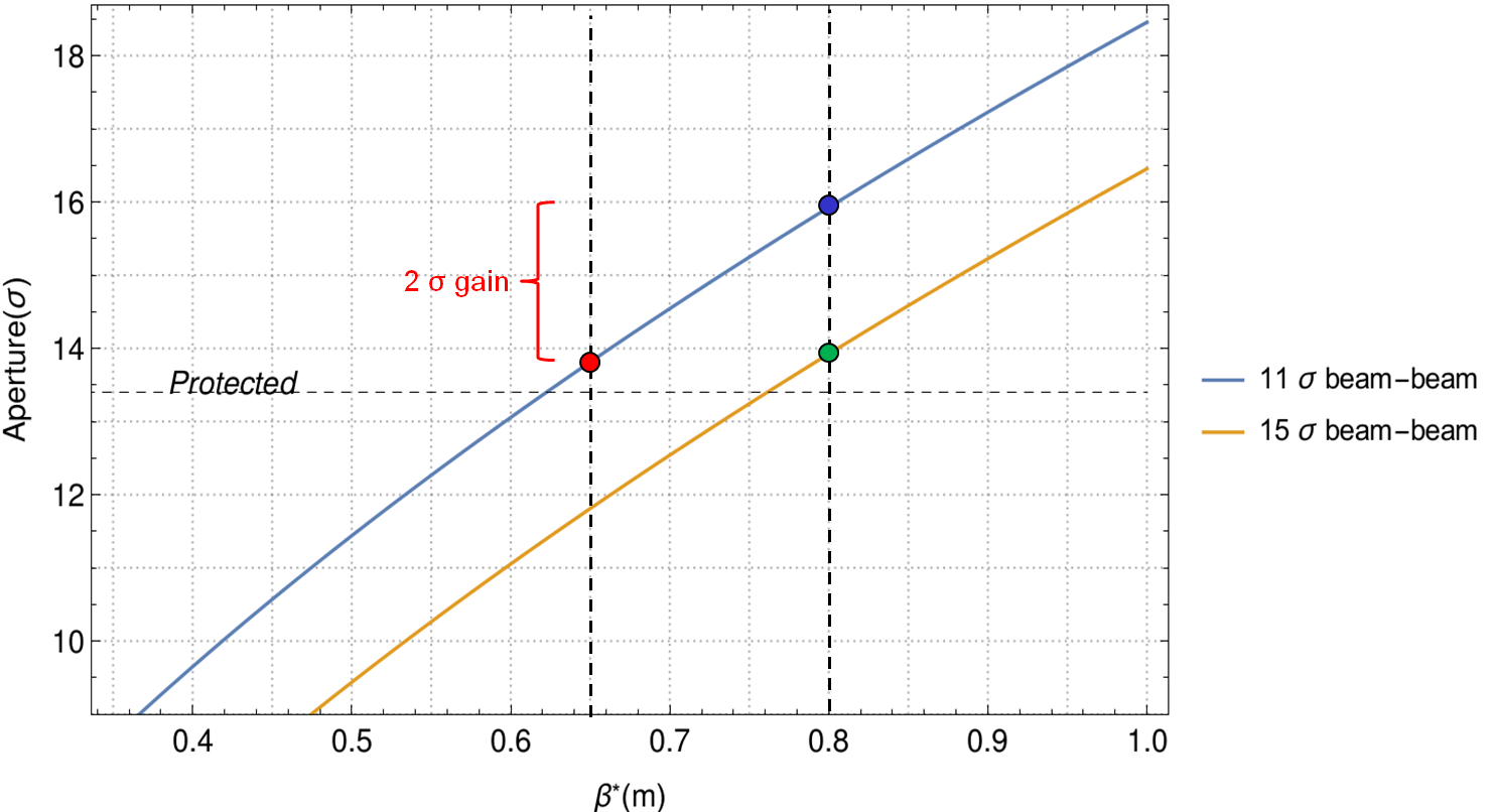
The required aperture as a function of is shown in Fig. 2, assuming a constant beam-beam separation of 11 (blue line). Under the assumption that the protected aperture is 13.4 , and that we operate at points rounded to a 5 cm spacing, the limiting that could be achieved is 65 cm (illustrated by the red dot in Fig. 2). This configuration, corresponding to a 160 rad half crossing angle, has been discussed in detail in Ref. [39]. It should be noted that the rounding up to 65 cm introduces a small aperture margin—the aperture prediction has anyway an error margin not smaller than the measurement precision of 0.5 .
It should be noted that several of the underlying assumptions on protection and stability contain uncertainties. For example, it cannot be guaranteed a priori that the orbit stability and optics correction will be as good as in 2012. Furthermore, the scaling to higher energy of instabilities and lifetime drops, presumably connected to the collimator impedance, is not known with a high accuracy. Therefore, in view of the approach of a relaxed start-up, it is wise not to start at the limiting configuration, but instead allow some additional margins.
Based on these considerations, it has been decided to start the 2015 LHC run at =80 cm [23]. If the beam-beam separation is kept constant at 11 , the baseline operating configuration is therefore the blue dot in Fig. 2, where a half crossing angle of 145rad is found. It can be seen in the figure that the step to =80 cm frees about 2 of aperture margin, which could be used in different ways depending on where it turns out to be needed.
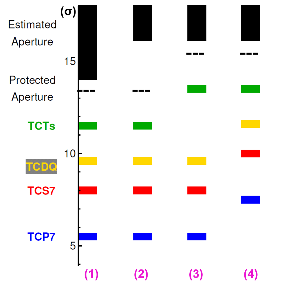
If no collimators are moved, the additional margin just increases the aperture budget and makes it more certain that the real measured aperture will be compatible with the protected one. This is illustrated schematically in steps (1) and (2) in Fig. 3.
In order to compensate for the uncertainty in orbit stability and optics correction, as well as the higher risk of asynchronous dumps at 6.5 TeV, the margin can be used to move out the TCTs so that they are better protected, as shown in step (3).
Step (4) in Fig. 3 illustrates yet another possibility, where all collimators are moved out in order to reduce the total machine impedance. This option could be envisaged if the beam stability turns out to be limited by impedance effects. A similar option, where all collimators but the primary (TCP) are moved out, could also be envisaged. This option would allow a learning curve for loss spikes with small TCP gaps.
In case the long-range beam-beam tune shift would turn out to be limiting, the additional aperture margin could also be used to increase crossing angle. This is illustrated by the green dot in Fig. 2. As can be seen, if all additional margin would be dedicated to the beam-beam separation, it could be increased to about 15 at =80 cm. This configuration corresponds to a half crossing angle of 195 rad.
It is not yet decided which of the different options for using the additional margin that will be used. One could also use a split between several of them. The partition of the margins could even be changed during the 2015 commissioning, when it is clearer where it is mostly needed, although some changes would require additional commissioning time. We list here some examples of realistic suggestions for the start-up:
-
•
All margin on machine protection: This option compensates for uncertainties on failure probabilities and, with the 11 beam-beam separation and tight collimators, it allows us to learn early on about potential limitations on beam stability.
-
•
1 on machine protection and 1 on beam-beam separation: This option allows a more relaxed squeeze with lower probability of instabilities, while maintaining a higher level of protection. It should be noted that 1 of aperture translates approximately into 2 of beam-beam separation, meaning a total separation of 13 and a half crossing angle of 170 rad.
8 Ways to push performance
Once the LHC has been successfully put into operation and a first period of stable beams has been established, it is reasonable to assume that the performance limitations will be better known. Then, the performance could be increased based on the operational experience and possible MDs. Several machine parameters could be changed to gain in luminosity performance:
- •
-
•
Smaller emittance: This is also a well-known and straightforward way to increase the luminosity. It is also limited by the injectors and beam stability, but also by machine protection considerations [7]. It introduces also an additional gain by allowing a smaller crossing angle in rad and therefore a larger aperture margin.
-
•
Collimator settings: If the margins in the hierarchy are reduced, e.g. by establishing the 2 retraction settings in Table 1, a smaller aperture can be protected, and thus a smaller tolerated. However, with tighter settings, the impedance increases. Whether this is tolerable has to be evaluated with beam. Based on further operational experience, the margins between the dump protection and the TCTs, as well as the margins between TCTs and triplets, might be decreased if the new integrated BPM buttons can be used to reduce orbit drifts from the center of the collimators. The less temperature-sensitive BPM electronics could also be used to determine whether some of the large orbit drifts between TCTs and triplets, observed in Run I, are real or an artifact of the measurements. In the future, we still hope to achieve nominal collimator settings in IR7 with a 1 retraction between the TCP and the secondary collimators (TCS). However, because of the impedance constraints, this is unlikely to be usable during Run II. Installing new TCSs made of materials with lower impedance could help. Furthermore, integrated BPMs in the TCS would help to ensure that the hierarchy is maintained in spite of the smaller margin.
-
•
Crossing angle: reducing the crossing angle at a given implies a gain in the required aperture. However, if the beam-beam separation is decreased, the long-range effect becomes more critical, in particular during the squeeze [14], which limits the smallest achievable crossing angle.
-
•
Aperture: unless additional margins are introduced at the start-up, the gain should be rather small. The aperture in Run I was found in measurements to be very close to the ideal one, and the same assumptions are used for Run II.
- •
We cannot a priori determine the exact limit of actual -values that could be reached later in the run, as many underlying parameters must be examined with beam. Instead, we give a few examples of possible configurations with pushed performance:
-
•
=65 cm: From Fig. 2 it is clear that =65 cm could be within reach even with rather conservative assumptions.
-
•
=55 cm: If beam studies show that the impedance is acceptable for reduced collimator settings with a 2 retraction in IR7 (see Table 1) =55 cm could be within reach if the aperture is at the limit of what can be tolerated. Alternatively, the main gain could come from the crossing angle. Keeping the mm kept settings, =55 cm and a crossing angle of 130 rad fits almost exactly within the protected aperture. This configuration corresponds to a beam-beam separation of 8.3 for an emittance of 3.75 m. If the emittance can be reduced to 2.5 m, the beam-beam separation with this crossing angle is about 10 . This configuration is possibly compatible with 6 dynamic aperture [14] but the limit would have to be deduced from beam studies.
-
•
=40 cm: This configuration could be within reach under optimistic assumptions [39]. For this ultimate scenario for Run II we assume the 2 retraction collimator settings, with the addition of using the BPM button collimators to their full potential. Furthermore, we assume a beam-beam separation of 10 at an emittance of 2.5 m. These assumptions are considered challenging but possible, although it is not given that this configuration can be used. It could also require significant beam experience and additional commissioning time. Based on the possibilities of reaching =40 cm, the optics will be commissioned down to this value already at the start-up, in order to have maximum flexibility. As an alternative to round optics, the configuration with =40/50 cm in the two planes might be easier to reach in terms of aperture and gives comparable luminosity.
9 Conclusions and outlook
The LHC will be re-started in 2015 after about two years of shutdown. Many hardware changes and upgrades have taken place and the machine will operate at a higher energy of 6.5 TeV energy and a shorter bunch spacing of 25 ns. Therefore, the machine behavior is less well known than at the end of Run I and the strategy for 2015 is to start carefully with the main aim to get the machine running safely and stably.
Based on these considerations, we have presented the LHC baseline parameters for the 2015 start-up, which we summarize for convenience in Table 2. Most notably, the LHC will start proton physics at =80 cm, a 145 rad half crossing angle, and 2012 the collimator settings kept in mm. It is at the time of writing not decided whether the nominal or BCMS beams from the injectors will be used. These parameters contain some margins which could be used for increased machine protection, or, in case of need, for a relaxed beam-beam separation or impedance.
Later in the run, a push in and performance can be envisaged, when the operational limits are well established based on beam experience. This pushed -value could be as low as 40 cm under optimistic assumptions.
| Parameter | Unit | Value at injection | Value at collision |
|---|---|---|---|
| Beam energy | TeV | 0.45 | 6.5 |
| at IR1/IR2/IR5/IR8 | m | 11 / 10 / 11 / 10 | 0.8 / 10 / 0.8 / 3 |
| half crossing angle at IR1/IR2/IR5/IR8 | rad | -170 / 170 / 170 / 170 | -145 / 120 / 145 / -250 |
| Tunes (H/V) | – | 64.28/59.31 | 64.31/59.32 |
| Parallel separation at IR1/IR2/IR5/IR8 | mm | 2 / 2 / 2 / 3.5 | 0.55 / 0.55 / 0.55 / 0.55 |
| Normalized emittance (BCMS/nominal) | m | / | / |
| Total number of bunches (BCMS/Nominal) | – | / 2748 | |
| Number of bunches colliding at IR1/5 (BCMS/Nominal) | – | / 2736 | |
| Bunch intensity | p | ||
| Bunch length (4) | ns | 1.0–1.2 | 1.0–1.25 |
| Collimator settings | – | 2012 mm kept | 2012 mm kept |
10 ACKNOWLEDGMENTS
The authors would like to thank numerous colleagues for input and discussions: H. Bartosik, X. Buffat, E. Chapochnikova, P. Collier, R. de Maria, G. Iadarola, V. Kain, E. Meschi, N. Mounet, Y. Papaphilippou, G. Papotti, G. Rumolo, B. Salvachua, B. Salvant, M. Solfaroli, R. Tomas, G. Valentino, D. Valuch, and M. Zerlauth
References
- [1] S. Myers. The Large Hadron Collider 2008–-2013. Int. J. Mod. Phys. A, 28:1330035, 2013.
- [2] M. Solfaroli et al. Re-commissioning of the Superconducting Circuits. Proceedings of the LHC Performance Workshop (Chamonix 2014), Chamonix, France, 2014.
- [3] E. Meschi et al. Experiments’ Expectations for 2015. Proceedings of the LHC Performance Workshop (Chamonix 2014), Chamonix, France, 2014.
- [4] J. Wenninger et al. Overall Strategy for Run 2. Proceedings of the LHC Performance Workshop (Chamonix 2014), Chamonix, France, 2014.
- [5] G. Iadarola et al. Scrubbing: Expectations and Strategy, Long Range Perspective. Proceedings of the LHC Performance Workshop (Chamonix 2014), Chamonix, France, 2014.
- [6] Y. Papaphilippou et al. Operational Beams for the LHC. Proceedings of the LHC Performance Workshop (Chamonix 2014), Chamonix, France, 2014.
- [7] V. Kain et al. Concerns with Low Emittance Beams Operation. Proceedings of the LHC Performance Workshop (Chamonix 2014), Chamonix, France, 2014.
- [8] A. Butterworth et al. ADT and RF after LS1. Proceedings of the LHC Performance Workshop (Chamonix 2014), Chamonix, France, 2014.
- [9] M. Giovannozzi et al. Optics options for the 2015 LHC run. Proceedings of the LHC Performance Workshop (Chamonix 2014), Chamonix, France, 2014.
- [10] N. Magnin et al. LHC beam dumping system status and readiness for LHC run II. Proceedings of the 5th Evian Workshop, Evian, France, 2014.
- [11] B. Auchmann et al. BLM Threshold Strategy (vs UFOs and Quenches). Proceedings of the LHC Performance Workshop (Chamonix 2014), Chamonix, France, 2014.
- [12] LHC Studies Working Group Day, 2014.09.02, 2014.
- [13] E. Todesco et al. Energy of the LHC after the 2013-2014 shutdown. Proceedings of the LHC Performance Workshop (Chamonix 2012), 2012.
- [14] T. Pieloni et al. Two beam effects. Proceedings of the 5th Evian Workshop, Evian, France, 2014.
- [15] M. Kuhn et al. Transverse emittance through the cycle. Proceedings of the 5th Evian Workshop, Evian, France, 2014.
- [16] N. Mounet et al. Impedance and instabilities. Proceedings of the 5th Evian Workshop, Evian, France, 2014.
- [17] J.E. Muller et al. Longitudinal parameters and beam induced heating. Proceedings of the 5th Evian Workshop, Evian, France, 2014.
- [18] E. Metral. Collective effects. presentation in the LHC Machine Committee, 2014.09.03., 2014.
- [19] S. Redaelli et al. Combined Ramp and Squeeze at the Large Hadron Collider. Proceedings of IPAC12, New Orleans, Louisiana, USA, page 157, 2012.
- [20] M. Solfaroli et al. Nominal Cycle and Options. Proceedings of the LHC Performance Workshop (Chamonix 2014), Chamonix, France, 2014.
- [21] O. S. Brüning et al. LHC design report v.1 : The LHC main ring. CERN-2004-003-V1, 2004.
- [22] S. Fartoukh. Achromatic telescopic squeezing scheme and application to the lhc and its luminosity upgrade. Phys. Rev. ST Accel. Beams, 16:111002, 2013.
- [23] LHC Machine Committee, 2014.09.03, 2014.
- [24] S. Fartoukh. LHCb crossing scheme for Run II and III. presentation in the LHC Machine Committee, 2014.06.19, 2013.
- [25] R.W. Assmann. Collimators and Beam Absorbers for Cleaning and Machine Protection. LHC Project Workshop - ’Chamonix XIV’, page 261, 2005.
- [26] R.W. Assmann et al. The Final Collimation System for the LHC. Proc. of the European Particle Accelerator Conference 2006, Edinburgh, Scotland, page 986, 2006.
- [27] R. Bruce et al. Simulations and measurements of beam loss patterns at the cern large hadron collider. Phys. Rev. ST Accel. Beams, 17:081004, Aug 2014.
- [28] A. Verwei et al. Quench limits. Presentation in the LHC collimation review 2013, 2013.
- [29] R. Bruce and R.W. Assmann. LHC -reach in 2012. Proceedings of the 2011 LHC beam operation workshop, Evian, France, 2011.
- [30] R. Bruce et al. Calculation method for safe in the LHC. Proceedings of IPAC’11, San Sebastian, Spain, page 1828, 2011.
- [31] C. Alabau Pons et al. LHC aperture measurements. Proceedings of IPAC’10, Kyoto, Japan, page 477, 2010.
- [32] C. Alabau Pons et al. IR1 and IR5 aperture at 3.5 TeV. CERN-ATS-Note-2011-110 MD, 2011.
- [33] R.W. Assmann et al. Aperture Determination in the LHC Based on an Emittance Blowup Technique with Collimator Position Scan. Proceedings of IPAC’11, San Sebastian, Spain, page 1810, 2011.
- [34] S. Redaelli et al. aperture measurements in the LHC interaction regions. Proceedings of IPAC12, New Orleans, Louisiana, USA, page 508, 2012.
- [35] C. Alabau Pons et al. IR2 aperture measurements at 3.5 TeV. CERN-ATS-Note-2012-017 MD, 2012.
- [36] R. Bruce et al. IR8 aperture measurements at injection energy. CERN-ATS-Note-2013-026 MD, 2013.
- [37] R. Bruce et al. IR2 aperture measurements at 4.0 TeV. CERN-ACC-NOTE-2013-0011 MD, 2013.
- [38] R. Bruce et al. Parameters for HL-LHC aperture calculations. CERN Report CERN-ACC-2014-0044, 2014.
- [39] R. Bruce and S. Redaelli. Collimation and -reach. Proceedings of the 5th Evian Workshop, Evian, France, 2014.