Optimization of a high efficiency FEL amplifier111Preprint DESY 14-161, September 2014
Abstract
The problem of an efficiency increase of an FEL amplifier is now of great practical importance. Technique of undulator tapering in the post-saturation regime is used at the existing x-ray FELs LCLS and SACLA lcls ; sacla , and is planned for use at the European XFEL, Swiss FEL, and PAL XFEL euro-xfel-tdr ; swiss-fel ; pal-xfel . There are also discussions on the future of high peak and average power FELs for scientific and industrial applications. In this paper we perform detailed analysis of the tapering strategies for high power seeded FEL amplifiers. Application of similarity techniques allows us to derive universal law of the undulator tapering.
pacs:
41.60.Cr; 29.20.-cI Introduction
Efficiency of FEL amplifier with untapered undulator is defined by the value of the FEL parameter . Application of the undulator tapering kroll-tapering allows to increase conversion efficiency to rather high values. In the framework of the one-dimensional theory the status of the problem of tapering has been settled, and it is generally accepted that optimum law of the undulator tapering is quadratic with the linear correction for optimization of the particle’s capture in the decelerating potential paladin-tap ; fawley-scharl ; fawley-2lg ; fawley-vinokur ; ssy-1993 ; handbook-91 ; physrep-95 ; book . Similar physical situation occurs in the FEL amplifier with waveguide with small waveguide parameter. In this case radiation is confined with the waveguide. Physical parameters of FEL amplifiers operating in infrared, visible, and x-ray wavelength range are such that these devices are described in the framework of three dimensional theory with an “open” electron beam, i.e. physical case of pure diffraction in a free space. In this case diffraction of the radiation is essential physical effect influencing optimization of the tapering process. Discussions and studies on optimum law of the undulator tapering in 3D case are in the progress for more than 20 years. Our previous studies were mainly driven by occasional calculations of perspective FEL systems for high power scientific (for instance, FEL based - collider ) and industrial applications (for instance, for isotope separation, and lithography gg-1995 ; mw-fel-nim ; litho-kw-jm3 ). Their parameter range corresponded to the limit of thin electron beam (small value of the diffraction parameter). In this case linear undulator tapering works well from almost the very beginning ssy-1993 . Comprehensive study devoted to the global optimization of tapered FEL amplifier with “open” electron beam has been presented in fawley-2lg . It has been shown that tapering law should be linear for the case of thin electron beam, optimum tapering at the initial stage should follow quadratic dependence, and tapering should start approximately two field gain length before saturation. New wave of interest to the undulator tapering came with x-ray free electron lasers. It is used now not only as demonstration tool bnl-tapering , but as a routine tool at operating x-ray FEL facilities LCLS and SACLA lcls ; sacla . Practical calculations of specific systems yielded in several empirical laws using different polynomial dependencies, application of tricks with detuning jumps, etc (see wu-tap-2012 ; gel-tap-2011 and references therein).
In this paper we perform global analysis of the parameter space of seeded FEL amplifier and derive universal law of the undulator tapering defined by the only diffraction parameter.
II Basic relations
We consider axisymmetric model of the electron beam. It is assumed that transverse distribution function of the electron beam is Gaussian, so rms transverse size of matched beam is ,where is rms beam emittance, is relativistic factor, and is focusing beta-function. In the following we consider rectified case of the “cold” electron beam and neglect space charge effects. Under this assumptions the FEL amplifier is described by the diffraction parameter book , and detuning parameter :
| (1) |
where is the gain parameter, is the detuning of the electron with the nominal energy . In the following electron energy is normalized as , where is the efficiency parameter (note that it differs from 1-D definition by the factor book ). The following notations are used here: is the beam current, is the frequency of the electromagnetic wave, , is the rms undulator parameter, , is the undulator wavenumber, 17 kA is the Alfven current, for helical undulator and for planar undulator. Here and are the Bessel functions of the first kind.
Equations, describing motion of the particles in the ponderomotive potential well of electromagnetic wave and undulator get simple form when written down in normalized form (see, e.g. book ):
| (2) |
where , and and are amplitude and phase of effective potential. Energy change of electrons is small in the exponential stage of amplification, , and process of electron bunching in phase lasts for long distance, . Situation changes drastically when electron energy change approaches to the unity. The change of phase on the scale of becomes to be fast, particles start to slip in phase which leads to the debunching of the electron beam modulation, and growth of the radiation power is saturated. operation. Undulator tapering kroll-tapering , i.e. adjustment of the detuning according to the energy loss of electrons, , allows to keep synchronism of electrons with electromagnetic wave and increase output power.
II.1 Radiation of modulated electron beam
FEL radiation is coherent radiation of the electron beam which is modulated at the resonance wavelength during amplification process. It is reasonable here to remember properties of the radiation of the modulated electron beam. Radiation power of modulated beam in helical undulator is given by mod-beam-2005 :
| (3) |
where is amplitude of modulation of the electron beam current (), and is Fresnel number. We note here that expression (3) is a crucial element for understanding the optimum law of the undulator tapering. Indeed, in the deep tapering regime some fraction of the particles is trapped in the regime of coherent deceleration. Thus, beam modulation is fixed, and asymptotically radiation power should be described by (3). One can easily find that both asymptotes of undulator tapering discussed in the introductory section: 1D model of (wide electron beam), and thin beam asymptote are well described by this expression. Asymptote of wide electron beam corresponds to large values of Fresnel number , and it follows from (3) that radiation power scales as . Asymptote of thin electron beam corresponds to small values of the Fresnel Number , and radiation power becomes linearly proportional to the undulator length, . Undulator tapering should adjust detuning according to the energy loss by electrons, and we find that tapering law should be quadratic for the case of wide electron beam, , and linear - for the case of thin electron beam, .
III Global optimization
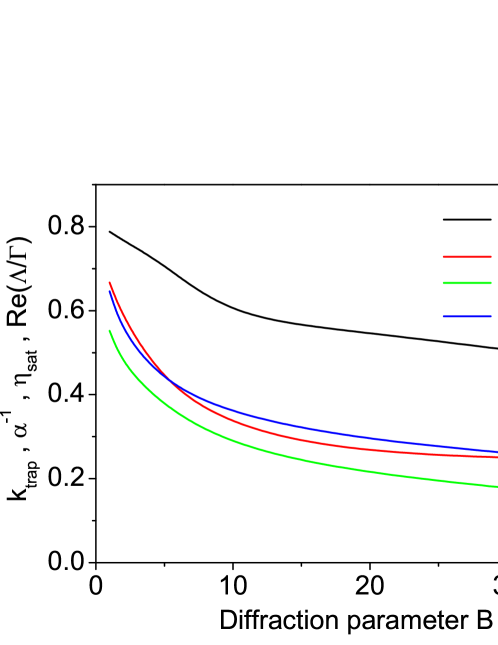
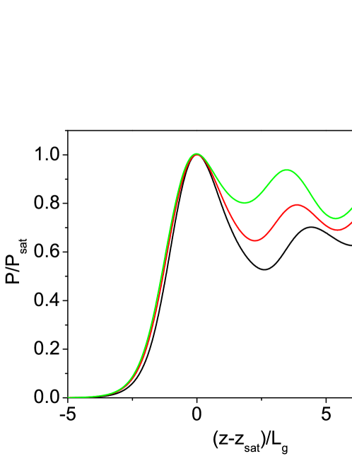
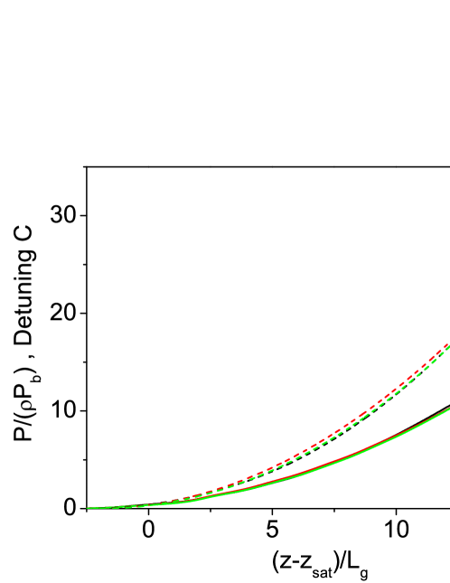
We start with global optimization of the parameter space. Simulations have been performed with three-dimensional, time-dependent FEL simulation code FAST fast . In the framework of the accepted model (cold electron beam) both, field gain and efficiency in the saturation, of the FEL amplifier tuned to exact resonance are defined by the only diffraction parameter (see Fig.1). Operation of the FEL amplifier before saturation is also defined by the diffraction parameter . One can clearly observe this from Fig. 2. Here longitudinal coordinate is normalized to the gain length , and radiation power is normalized to the saturation power. When amplification process enters nonlinear stage, output power is function of two parameters, diffraction parameter and reduced undulator length.
Now we come to the problem of efficiency increase with undulator tapering. First, we solve this problem using approach of straightforward global optimization. The function of optimization is to find maximum of the output power at the undulator length exceeding ten field gain lengths. We divide undulator into many pieces and change detuning of all pieces independently. We apply adiabatic (smooth) tapering, i.e. we prevent jumps of the detuning on the boundary of the sections. Number of sections is controlled to be large enough to provide the result which is independent on the number of sections. Then we choose tapering law corresponding to the maximum power at the exit of the whole undulator. This global optimization procedure has been performed in the practically important range of diffraction parameters from to . Results of this global optimization are summarized in Fig. 4. Ratio of the normalized power to the normalized detuning gives us the value of trapping efficiency of electrons into the regime of coherent deceleration, . This universal function of diffraction parameter is plotted on Fig: 1. We find that optimum trapping factor approaches values of 80% for , and falls down to 45% for . It is interesting to notice that for it scales roughly as , similar to other FEL characteristics like FEL gain and saturation efficiency.
IV Universal tapering law
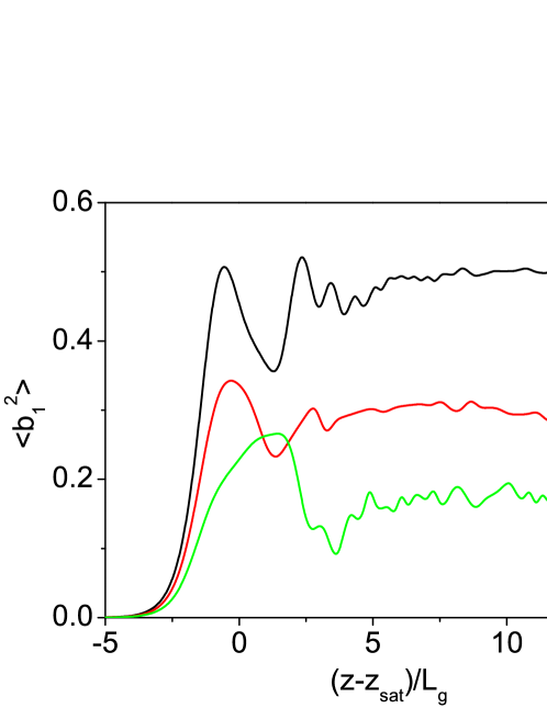
It comes from global optimization that in the whole parameter range undulator tapering starts from the value of before saturation. This is not surprising if we look on Fig. 2. Optimum undulator tapering should compensate loss of the electron energy which is in fact follows identical parametric dependence on the gain for all values of diffraction parameter. Next observations come from the analysis of the beam modulation. The first observation is that the beam modulation at the initial stage of the nonlinear regime follows similar behavior for all diffraction parameters (see Fig. 4). This gives a hint that initial capture of the particles is performed in a similar way in the whole parameter range. The second observation is that the beam modulation after trapping of the electrons to the coherent deceleration process remains constant along the undulator, and it is universal function of the diffraction parameter (see Fig. 4). This is gives us the main hint which we discussed in the previous section. I.e., excluding trapping transition stage, we deal with radiation of the modulated electron beam (3). Main essence of our study is to apply parametrical dependence like (3) to fit optimum detuning pattern in Fig. 4 such that condition of optimum tapering is preserved:
| (4) |
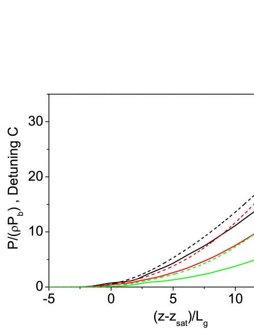
with Fresnel number fitted by . Thus, we try to fit optimum detuning with three parameters: , and . Here undulator length is normalized to the gain parameter, . One parameter of this fit, start of the undulator tapering is firmly fixed by the global optimization procedure, . Another parameter of the problem, , is rather well approximated with the linear dependency on diffraction parameter, . Remaining parameter, is plotted in Fig. 1. It is slow function of the diffraction parameter , and scales approximately to as all other important FEL parameters presented in Fig. 1. Thus, application of similarity techniques gives us an elegant way for general parametrical fit of such complicated phenomena as optimum undulator tapering. Actually, accuracy of this fit is pretty good giving the results for optimum detuning which are close to the global optimum. We illustrate with Fig. 5 tapering law (4) for specific value of the diffraction parameter . Curves in black color are normalized power and detuning derived from global optimization. Red dashed curve is detuning given by (4) with (see Fig. 1, and (according to relation ). The solid curve in red color is normalized FEL efficiency simulated using detuning (4). We see good agreement of the fit with global optimization. The same situation occurs in the whole range of traced values of diffraction parameter . Such a good agreement is not surprising since fitting is based on very clean parametric dependencies, and numerical simulations just provided relevant numerical factors.
IV.1 Rational fit
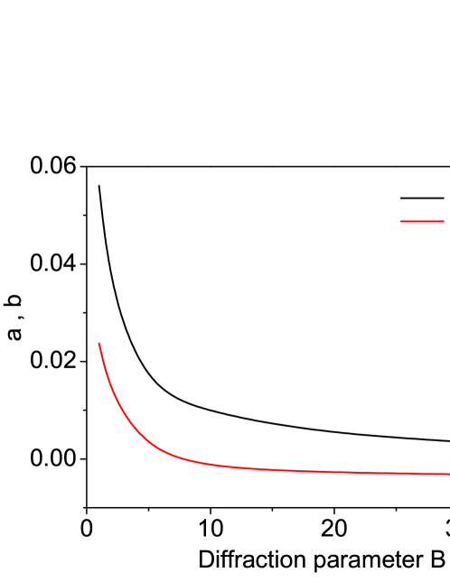
Analysis of expression (4) shows that it has quadratic dependence in for small values of (limit of wide electron beam), and linear dependence in for large values of (limit of thin electron beam). Natural idea comes to try fit with rational function which satisfies both asymptotes. The simplest rational fit is:
| (5) |
Coefficients and are universal functions of diffraction parameter , and are plotted in Fig. 6. Start of the undulator tapering is set to the value suggested by the global optimization procedure. Analysis of plots presented in Fig. 5 shows that fit of the universal tapering law with rational also works well.
IV.2 Trapping process

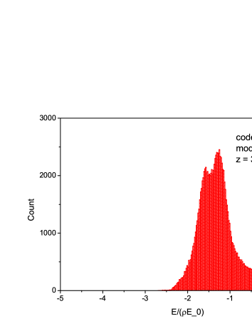
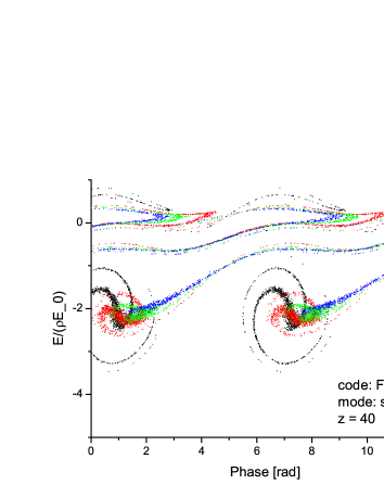
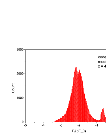
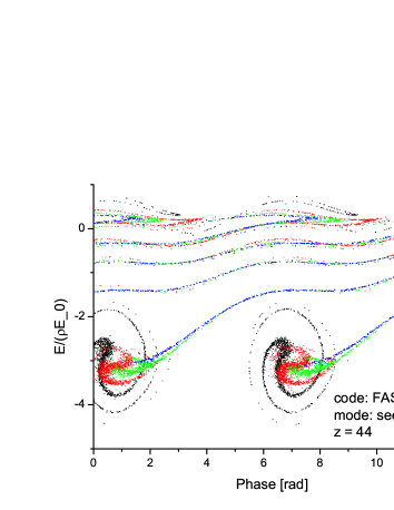
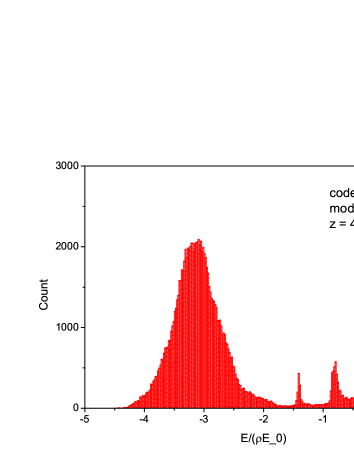
We finish our paper with illustration of the trapping process. Trapping efficiency is plotted in Fig. 1. Trapping efficiency falls down with diffraction parameter . This is natural consequence of diffraction effects discussed earlier (see, e.g. book , Chap. 4). For small value of the diffraction parameter gradient of the field of the beam radiation mode across the electron bunch is smaller than for large values of diffraction parameter. In the latter case we obtain situation when electrons located in the core of the electron beam are already fully bunched while electrons on the edge of the beam are not bunched yet. As a result, number of electrons with similar positions on the energy-phase plane falls down with the growth of the diffraction parameter, as well as trapping efficiency into the regime of coherent deceleration. The trapping process is illustrated with phase space plots presented on Fig. 7 for the value of diffraction parameter . Top, middle, and bottom plots correspond to the points of = 2.5, 3.9 and 5.3 on Fig. 4. Different color codes (black to blue) correspond to different locations of the particles across the beam (core to edge. We see that particles in the core of bunch (black points) are trapped most effectively. Nearly all particles located in the edge of the electron beam (blue points) leave stability region very soon. Trapping process lasts for several field gain length when trapped particles become to be isolated in the trapped energy band for which undulator tapering is optimized further. For specific value of the diffraction parameter it is not finished even at three field gain lengths after saturation, and non-trapped particles continue to populate low energy tail of the energy distribution (see right column of Fig. 7). Recently we have been invited to the discussion on the details of trapped particles distribution in the phase space observed experimentally at LCLS behrens-bands1 . Graphs presented in Fig. 7 give a hint on the origin of energy bands which are formed by non-trapped particles. This is consequence of nonlinear dynamics of electrons leaving the region of stability. Actually, similar effect can be seen in the early 1D studies handbook-91 ; physrep-95 .
V Discussion
In this paper we derived general law for optimum undulator tapering in the presence of diffraction effects (4). Purified case of “cold” electron has been considered. This allowed us to isolate diffraction effects in the most clear form. It has been found that universal function of the undulator tapering depends on the only diffraction parameter. Fit of the universal tapering law with rational function (5) requires fulfillment of two asymptotes of the tapering law: quadratic at the initial stage (wide beam asymptote), and linear for very long tapering section (thin beam asymptote). It is essentially simple, and can be very convenient for optimization of practical systems. Tapering law is described with simple analytical expressions with two fitting coefficients. Extension of this approach to practical life (including energy spread and emittance) is pretty much straightforward and will result in corrections to the fitting coefficients without changing general law given by (4). The same law is evidently applicable to SASE FEL as well with relevant correction of fitting coefficients.
VI Acknowledgement
We are grateful to William Fawley for useful discussion on the problem of undulator tapering which continued through many years. We are grateful to Vadim Banine and Vivek Bakshi, contacts with them and other members of industrial community stimulated our interest to the development of high power FEL systems. We thank Christopher Behrens for attracting our attention to deeper analysis of the trapping process (energy bands) and for useful discussions.
References
- (1) P. Emma et al., Nature Photonics 4(2010)641
- (2) T. Ishikawa et al., Nature Photonics 6(2012)540 544
- (3) M. Altarelli et al. (Eds.), XFEL: The European X-Ray Free-Electron Laser. Technical Design Report, Preprint DESY 2006-097, DESY, Hamburg, 2006 (see also http://xfel.desy.de).
- (4) R. Ganter (Ed.), Swiss FEL Conceptual Design Report, PSI Bericht Nr. 10-04, April 2012
- (5) H.S. Kang, K.W. Kim, I.S. Ko, Current Status of PAL-XFEL Project. Proc. IPAC 2014 Conf., paper THPRO019 (2014), http://accelconf.web.cern.ch/AccelConf/IPAC2014/papers/thpro019.pdf
- (6) N.M. Kroll, P.L. Morton, and M.N. Rosenbluth, IEEE J. Quantum Electron. 17, 1436 (1981).
- (7) T.J. Orzechowski et al., Phys. Rev. Lett. 57, 2172 (1986).
- (8) R.A. Jong, E.T. Scharlemann, W.M. Fawley Nucl. Instrum. Methods Phys. Res. A272, 99 (1988)
- (9) W.M. Fawley, Nucl. Instrum. Methods Phys. Res. A375, 550 (1996)
- (10) W.M. Fawley et al., Nucl. Instrum. Methods Phys. Res. A483, 537 (2002)
- (11) E.L. Saldin, E.A. Schneidmiller and M.V. Yurkov, Opt. Commun. 95, 141 (1993).
- (12) Review by E.T. Scharlemann in Laser Handbook, Volume 6, Free electron lasers, eds. W.B. Colson, C. Peilegrini and A. Renieri (North Holland, Amsterdam, 1991).
- (13) E.L. Saldin, E.A. Schneidmiller and M.V. Yurkov, Physics Reports 260, 187 (1995).
- (14) E.L. Saldin, E.A. Schneidmiller, M.V. Yurkov, “The Physics of Free Electron Lasers” (Springer-Verlag, Berlin, 1999).
- (15) E.L. Saldin, V.P. Sarantsev, E.A. Schneidmiller and M.V. Yurkov, Nucl. Instrum. and Methods A339. 583 (1994).
- (16) C. Pagani, E.L. Saldin, E.A. Schneidmiller and M.V. Yurkov, Nucl. Instrum. and Methods A455, 733 (2000).
- (17) E.A. Schneidmiller, V.F. Vogel, H. Weise and M.V. Yurkov, Journal of Micro/Nanolithogrphy, MEMS, and MOEMS 11(2), 021122 (2012).
- (18) Y. Jiao et al. Phys. Rev. ST Accel. Beams 15, 050704 (2012).
- (19) G. Geloni, V. Kocharyan, and E. Saldin, DESY Report 11-049, 2011.
- (20) Y Hidaka et al., Proceedings of 2011 Particle Accelerator Conference, New York, NY, USA, THP148 (2011). https://accelconf.web.cern.ch/accelconf/PAC2011/papers/thp148.pdf
- (21) E.L. Saldin, E.A. Schneidmiller and M.V. Yurkov, Nucl. Instrum. and Methods A539, 499 (2005).
- (22) E.L. Saldin, E.A. Schneidmiller, and M.V. Yurkov, Nucl. Instrum. and Methods A 429, 233 (1999).
- (23) C. Behrens, Talk at the Workshop on Advanced X-Ray FEL Development , May 23, 2014, Hamburg.