Flow patterns and heat transfer around six in-line circular cylinders at low Reynolds number
Abstract
The flow field and the heat transfer around six in-line iso-thermal circular cylinders has been studied by mean of numerical simulations. Two values of the center to center spacing ( and , where is the cylinder diameter) at Reynolds number of and Prandtl number of has been investigated. Similarly to the in-line two cylinder configuration, in this range a transition in the flow and in the heat transfer occurs. Two different flow patterns have been identified: the stable shear layer (SSL) mode and the shear layer secondary vortices (SLSV) mode, at and spacing ratio (), respectively. At the flow pattern causes the entrainment of cold fluid on the downstream cylinders enhancing the heat transfer. On the other hand at two stable opposite shear layer prevent the cold fluid entrainment over the downstream cylinders reducing their heat exchange. The overall time average heat transfer of the array is enhanced up to 25% decreasing the spacing ratio from to . Furthermore, it is found that the increased heat transfer is related to the phase shift between the Nusselt time series of successive cylinders.
i
I Introduction
The fluid flow around bluff bodies is often subject of interest in theoretical and applied physics. Heat transfer around an array of circular cylinders involves a variety of engineering applications such as rod structure of the nuclear reactors, compact heat exchangers for electronic components and pin-fins heat exchangers for micro-devices (Ali Kosar and Peles, (2005)). In the micro-devices the Reynolds number ranges between and the flow is mainly two-dimensional (Carmo et al., (2010)). The flow characteristics play a key role in understanding how the array is able to enhance or decrease the heat exchange, the mixing layer or the unsteady body forces (Chatterjee et al., (2009); Lo and Su, (2012); Lu et al., (2012); Fornarelli and Vittori, (2009)). Sreedharan et al., (2008) experiments, on different pin geometries, highlight that the heat transfer enhancement is related to the pin wake characteristics. In particular the vorticity dynamics and the vortex street formation around multiple bodies is strictly related to the wake interaction (Hanson and Ziada, (2011); Rinaldi and Païdoussis, (2012); Ziada and Oengören, (1992)).
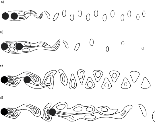
The simple two cylinders configuration has been discussed extensively and it represents a starting point to study the flow around multiple bluff bodies (Ben Meftah and Mossa, (2013); Chan et al., (2011); Jester and Kallinderis, (2003); S. Mittal and Kumar, (2001); Prasanth and Mittal, (2009); Sharman et al., (2005); Sumner et al., (2000)). According to the literature, a well-known drag inversion separation has been identified. Considering two cylinders aligned with the flow direction and defining the distance between their centers, the drag inversion separation represents the distance for which the mean drag coefficient of the downstream cylinder switches from positive to negative value due to the suction effect of the upstream cylinder. A spacing larger than the drag inversion separation makes positive the downstream cylinder drag coefficient and a vortex shedding in the gap between the cylinders appears. This flow is induced by the influence of both the cylinders and it is called wake interference (Jester and Kallinderis, (2003)). Sharman et al., (2005) studied numerically the flow around two tandem circular cylinders at for the spacing ratio between and finding the drag transition between and . In this configuration Sumner et al., (2000) identified three different flow patterns increasing the distance between the cylinders called: single bluff body (SBB) mode, shear layer reattachment (SLR) mode and synchronization of vortex shedding (SVS) mode. In SBB mode ( depending on Re) the two cylinders influence the flow field like a single bluff body. In SLR mode () the vortices shed by the upstream cylinder reattach at the downstream cylinder surface and evolve in a von Karman vortex street. For larger than a critical value both the cylinders shed vortices at the same frequency and this mode is called SVS. Even though Sumner et al., (2000) investigated the flow at , recently Wang et al., (2010) founds, at low Reynolds numbers (), the same flow patterns; moreover, at larger spacing ratio than the above-mentioned critical one, a new mode called the secondary vortex formation (SVF) has been discovered. The SVF mode is characterized by secondary vortex street in the wake of the downstream cylinder. A schematic of the vorticity patterns of the above-mentioned modes is reported in fig.1 as described in Wang et al., (2010).
The flow dynamics of two cylinders highlight the strong dependence of instability by the geometry and the flow conditions, therefore its relation to multiple bodies configuration is not straight forward. The two cylinder configuration help the scientists and engineers to better understand the physical mechanisms that influence the bluff bodies – flow interaction, but practical engineering applications, i.e. tube bundle in heat exchanger, involve numerous bluff bodies arranged in different array. In literature several works extend the two cylinder configuration to multiple array, in particular the six in-line configuration has been studied. More insight is provided by Liang et al., (2009), Sewatkar et al., (2012) and Bao et al., (2012) that studied the flow characteristics of six in-line circular or square cylinders at low Reynolds number. They focused on the near wake flow structures omitting the analysis of the far wake structures. Liang et al., (2009) founds the critical spacing between and of the center to center distance for which the drag and lift coefficients of each cylinder change significantly.
In this paper we made richer the six in-line circular cylinders results, investigating by means of frequency analysis the time dependent cylinder forces and flow velocities showing the pattern topology of the far wake. Two modes called stable shear layer (SSL) and shear layer secondary vortices (SLSV) are found at and spacing ratio, respectively. Farther the cylinders has been heated and maintained at a constant temperature in order to study the effects of the fluid flow on the heat transfer. The forced convection is considered. In this case the flow is not influenced by the temperature since the buoyancy force is much smaller than the convective force. Considering the heat and mass transfer without buoyancy, two dimensionless control parameters exist, the Reynolds () and the Prandtl () number. They are defined as:
| (1) |
where , , and are, respectively, the inflow velocity, the cylinder diameter, the kinematic viscosity of the fluid and its thermal diffusivity. In these hypotheses the temperature is a scalar quantity transported by the flow field with a proper diffusivity term that depends on the Prandtl number. In this paper we used air as working fluid with a Prandtl number at of . In Harimi and Saghafian, (2012) the numerical simulation of forced convection at with two in-line isothermal cylinders shows an heat transfer enhancement increasing the spacing ratio. Increasing the spacing ratio the heat exchange is enhanced especially at the transition, . It is worth to note that also the local Nusselt number distribution on the surface of the downstream cylinder changes in the transition range (Mahír and Altaç, (2008)) due to the shedding vortices in the gap between the cylinders. The results of the six in-line cylinders configuration reveal a clear evidence that, on the contrary of the two tandem cylinder configuration, the overall heat transfer increases up to the diminishing the spacing ratio from to .
This paper is organized as follows. First the numerical method is presented and validated reproducing the flow around a single cylinder and a two tandem circular cylinders configuration according to the literature. The results of the six circular cylinders in-line configuration around the critical spacing is presented investigating the near and the far wake flow characteristics. Finally the heat transfer around six in-line cylinders in the case of forced convection at Prandtl number of is reported.
II Governing equations and numerical method
The dimensionless two-dimensional incompressible Newtonian Navier-Stokes reads:
| (2) |
| (3) |
| (4) |
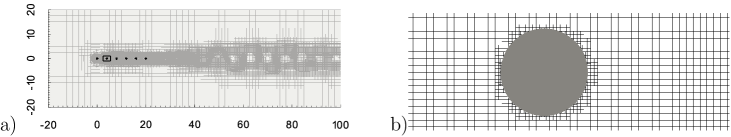
The stream-wise and transverse directions of the Cartesian reference frame are defined as and , respectively. The dimensionless velocity vector is with and the stream-wise and the transverse velocity components, respectively. The dimensionless pressure, temperature and time are, respectively, , and . Direct numerical simulations has been considered by mean of Gerris numerical code described in Popinet, (2003) and Popinet, (2009). The equations (2), (3) are solved using a classical fractional step projection method. The advection terms in the equations (2) and (4) are computed using a Godunov procedures with a second order upwind method and the viscous terms are treated implicitly with a Crank-Nicholson method. The cylinder surfaces within the domain are treated with a volume-of-fluid approach (Popinet, (2009)). The boundary conditions at the inflow are defined Dirichlet for the velocity and the temperature with constant values , and and Neumann for the pressure, . At the outflow there are Dirichlet boundary condition for the pressure and Neumann condition for the velocity components and the temperature . In order to avoid any influence of the outflow on the dynamics of the shedding vortices, the outflow boundary has been placed - cylinder diameters far from the downstream cylinder, where the wake disturbances have been dissipated due to the viscosity (Kloker et al., (1993)). The boundary conditions in the transverse direction is set as free-slip, , and . A Dirichlet boundary condition for the temperature is set at the solid cylinder surfaces, . An adaptive mesh refinement with a quad-tree approach is used. A static mesh refinement at the solid surfaces and a dynamical mesh refinement generated according to the local velocity and temperature gradient are implemented. In figure 2 a sketch of the whole numerical domain for the six in-line cylinders configuration and an instantaneous cells distribution behind the downstream cylinder is depicted. In table 1 the details of the computational grid are listed. The total amount of grid points cannot be reported since they are time dependent. The code is parallelized using distributed memory approach (MPI protocol) so multi-processors simulations have been performed. The simulations has been run on a Linux cluster. More details on the numerical code (Gerris) are described in Popinet, (2003).
III Validation study
III.1 Flow around a single cylinder
According to the well known problem of a single cylinder immersed in a stream flow, a validation study about the computational grid has been performed at . The dimensions of the numerical domain have been chosen in order to reduce the boundary influence on the solution. The boundaries distances from the center of the cylinder are: from the inlet, from the lower and upper boundaries and from the outlet. Four different grid resolutions have been chosen: grid , grid , grid and grid from the coarsest to the finest, respectively. The grid details are reported in table 1. No artificial perturbations are added to the boundary condition in order to trigger the vortex shedding. For the above listed tests we get the stationary solution after dimensionless time units, after that we collect the statistics for time units.
| Grid | Cylinder grid points | Minimum grid size | Maximum grid size |
|---|---|---|---|
| 1 | |||
| 2 | |||
| 3 | |||
| 4 |
| Chan et al., (2011) | ||||
|---|---|---|---|---|
| Park et al., (1998) | ||||
| Sharman et al., (2005) | ||||
| Ding et al., (2007) | ||||
| grid 1 | ||||
| grid 2 | ||||
| grid 3 | ||||
| grid 4 |
The control parameters are: the time-average drag coefficient, , the standard deviation of the drag and the lift coefficients, , and the Strouhal number, where is the frequency of . The results of the test cases are compared with the results of Chan et al., (2011), Park et al., (1998), Sharman et al., (2005), Ding et al., (2007)(see table 2). The results are in agreement with the data in literature. Thus, the grid resolution of grid is the best compromise between computational cost and accuracy.
III.2 Flow around two tandem cylinders
As described in the introduction the flow around multiple bodies implies a flow field that could be completely different compared to the flow around a single body. Especially in the in-line configuration the upstream body influences the flow dynamics on the downstream ones. In Sharman et al., (2005) the fluid flow around two circular cylinders in a tandem configuration has been described. The force characteristics on both the cylinders are excerpted. In the present work numerical experiments at a spacing ratio of , , and have been performed. All the tests converge in dimensionless time units except the case at a spacing ratio of that converges after about time units. All the statistics have been collected for time units after the convergence. For these simulations the dimensions of the numerical domain are in the stream-wise and transverse direction, respectively. The boundary distances from the center of the upstream cylinder are: from the inlet, the lower and the upper boundary and from the outlet.

In fig. 3a and 3b the comparison of the time average, , and the standard deviation, , of the drag coefficients for the upstream (1) and downstream cylinders (2), respect to Sharman et al., (2005), are reported. The distance for which the mean drag coefficient of the second cylinder is significantly enhanced is called critical center-to-center spacing. It is correctly reproduced by the current test as reported in fig. 3a.
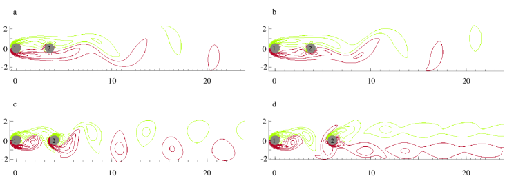
The vorticity patterns at different spacing are reported in figure 4 where the flow pattern transition between a spacing ratio of and is shown. In figures 4a-b for a spacing ratio of and respectively the vorticity field in the gap appears split in an upper negative vorticity zone (green/light grey) and a lower positive vorticity zone (red/dark grey). The wakes are elongated in the stream-wise direction. For a spacing ratio of and (see figure 4c-d) the wake shedding is completely triggered and it influences the gap region. The unsteady wake of the first cylinder interacts with the cylinder generating a more unstable wake downstream. The differences in the shedding frequency, for changing the spacing ratio, can be seen qualitatively looking at the vorticity iso-lines of the wakes (figure 4) and quantitatively in figure 3d with the results of Sharman et al., (2005) and Li et al., (1991). As reported in Sharman et al., (2005) the results of Li et al., (1991) are not reliable according to insufficient domain size, grid resolution and too large time step. Whereas, there is a good agreement with the results of Sharman et al., (2005).
IV Results: six in-line circular cylinders
IV.1 Flow characteristics
The flow around six in-line cylinders is investigated. For this configuration Liang et al., (2009) found a transition in the values of the average drag coefficient at between a spacing ratio of .
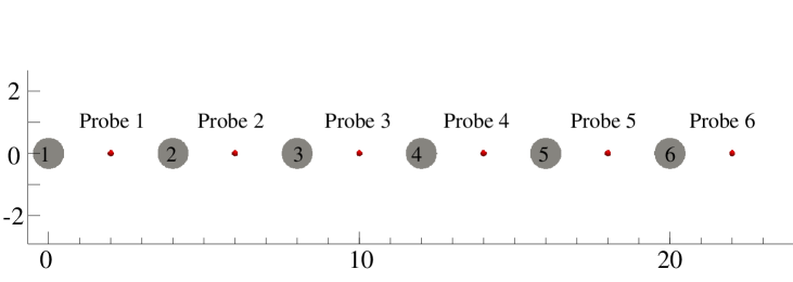
One probe per each gap has been located between the cylinders and one behind the last cylinder, where the pressure, the velocity components and the vorticity are sampled (see figure 5). The statistics are collected from to dimensionless time units in order to ensure the convergence with a sufficient number of samples.
The results for six in-line circular cylinders have no reference data in literature, except the numerical results of Liang et al., (2009). In table 3 the main Strouhal number of the vortex shedding for and are compared. Some differences are present, likely because of some lack in the domain size and statistical accuracy of Liang et al., (2009) results. The Liang outflow has been set far from the last cylinder respect to considered in the present results. The following flow patterns analysis will highlight that the far field wake evolution could affect the equations solution, especially for the case of six in-line cylinder configuration. Moreover, here about shedding periods of flow transient phase have been discarded and then the statistics have been collected for shedding cycles. Otherwise, the transient shedding periods and shedding cycles of statistics considered by Liang with the same initial conditions (zero velocity and pressure field) are not enough to ensure the statistical convergence of the mean quantities, according to the long transient phase that this configuration has, and the few statistical samples considered.
| Liang et al., (2009) | Present results | |
|---|---|---|
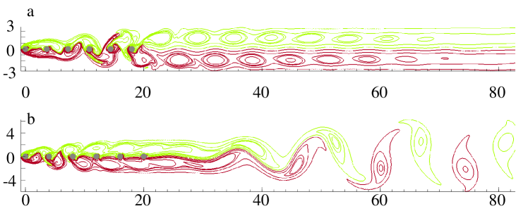
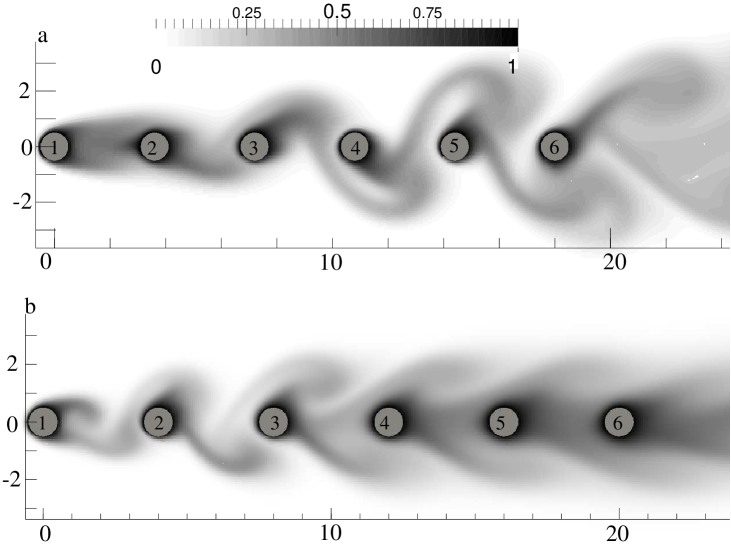
In figure 6 the instantaneous vorticity contours for a spacing ratio equal to and are shown. For a spacing ratio (figure 6a) there is a quasi-steady recirculation flow in the gap between the cylinders and . On the other hand, starting from cylinder to cylinder , the vortex shedding can be distinguished.
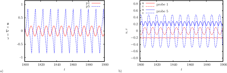
In figure 7 the time series of the vorticity and of the velocity components collected by the probe and the probe are shown. The vorticity time series in the gap between cylinder and (probe ) has a sinusoidal behaviour with an amplitude smaller than those recorded in the gap between cylinder and (probe ) where the vortex shedding strongly affects the flow field (see figure 7a). Therefore, the negative stream-wise velocity component in probe confirms the presence of a quasi steady recirculation flow between cylinder and (see figure 7b). The force components have been computed for each cylinder as dimensionless force coefficients: lift , , and drag .
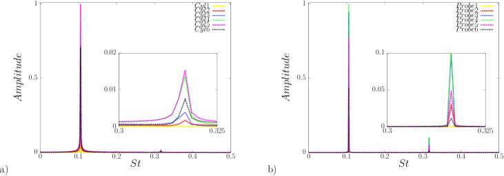
In figure 8a the amplitude spectra of the for a spacing ratio of is shown. For all the cylinders the main shedding frequency is equal to . A high secondary frequency at , equal to the third harmonic of the above mentioned main frequency, can be distinguished on cylinder with very narrow band-width. These small structures, coming from upstream region (probe ), are dissipated behind the last cylinder (probe ). Looking at figure 6a, the case at spacing ratio reveals, in the wake of the last cylinder, two rows of counter-rotating shedding vortices. We call this mode: stable shear layer (SSL) mode.
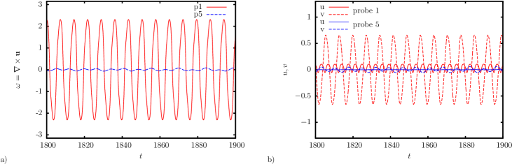
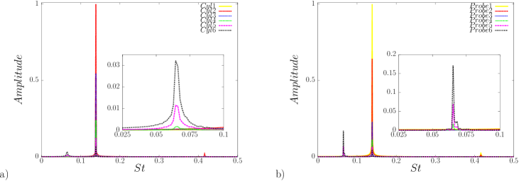
For a spacing ratio of different flow patterns can be distinguished respect to the case at (see figure 6b). The vortex shedding takes place at the upstream cylinders ( - ) and it interacts with cylinder producing two opposite vorticity shears that slip along the successive cylinders. In the gap regions of the downstream cylinders there are low vorticity zone as showed in fig9, where the amplitude of the vorticity in the probe is smaller than that in the probe . The amplitude spectra of the in the cylinder positions and of transverse velocity component, , in the probe positions for are reported in fig.10. The main oscillating frequency is increased from at to at . Varying the spacing from to plays an important role in the modification of the flow structures leading to a change of the heat exchange as described in detail in the following section. In this case too, there is an high frequency peak, , it is equal to the third harmonic of the main frequency, . Moreover at there is the presence of the low frequency peak in the amplitude spectra of and , see figure 10. This low frequency peak is generated by the flow field instability in the wake region. The vorticity pattern in the wake region (see fig.6b) highlights that the two shear layers take place at the cylinder and the cylinder and they slip along the downstream cylinders. After about downstream the last cylinder () the shear layers become unstable and a secondary wake starts to shed vorticity at a low frequency respect to the shedding frequency of the upstream cylinders. We call this mode shear layer secondary vortices (SLSV) mode.
A quantitative evidence of the flow transition between SSL and SLSV mode is showed in table 4. The value of suddenly increases from to at a spacing ratio of and , respectively. On the other hand there is a sudden decrease of the each time-average drag coefficient of the cylinders , , (, , ) for increasing the spacing ratio from to . It is worth to note the drag reduction on the entire row. The overall mean drag coefficient () decreases from to therefore the drag is reduced up to .
| , | , | , | , | , | , | , | |
|---|---|---|---|---|---|---|---|
| , | , | , | , | , | , | , | |
| , | , | , | , | , | , | , |
IV.2 Heat transfer analysis
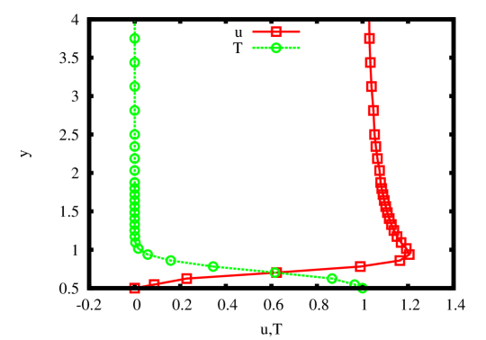
The analysis of the flow field around six in-line circular cylinders reveals the transition between different patterns according to the space ratio, . In this section the ability of the flow structures in enhancing the heat transfer between the cylinders and the surrounding fluid has been investigated for the spacing ratio of and . A Prandtl number equal to has been considered in order to reproduce the heat transfer for a fluid with air thermal diffusivity. For all the simulations the temperature of the cylinders () and the temperature of the inflow () has been kept constant. The dimensionless temperature is defined as . Being the thermal boundary layer thicker than the viscous one () no grid modification has been required. In order to check the correctness of the boundary layer resolution near the cylinders, in fig.11 the instantaneous dimensionless velocity and temperature profiles above the first cylinder for have been reported, where , and are the dimensionless transverse coordinate, stream-wise velocity component and the temperature, respectively. As follows in fig.17a, the first cylinder has the highest average Nusselt number, thus the thinnest boundary layer is expected to be there. Within the thermal and viscous boundary layer thickness, there are at least grid points (see fig.11).
The heat flux transferred from the solid body to the flow can be calculated as the conductive heat exchange at the solid wall being the fluid velocity at the wall equal to zero:
| (5) |
where is the thermal conductivity, is the polar angle respect to the center of the cylinder, and are the dimensional and the dimensionless temperature gradient normal to the cylinder surface, respectively.
It has to be equal to the convective heat flux per unit length transferred that reads:
| (7) |
The local Nusselt number represents the dimensionless local heat flux:
| (8) |
The mean (surface-averaged) Nusselt number along the cylinder surface is defined as follows:
| (9) |
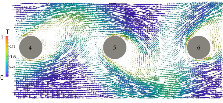
How the spacing between the cylinders affects the heat exchange? The unsteady behaviour of the flow field due to the oscillating vorticity behind the cylinders affects the heat transfer. The vorticity field influences the temperature distribution of the fluid in the near field (see fig.12). In fig.13 the velocity vectors colored with their local temperature at shows that the flow field causes the entrance of colder fluid over the cylinders. This phenomenon enhances the heat exchange because of the higher thermal gradient between the cylinders and the surrounding fluid.
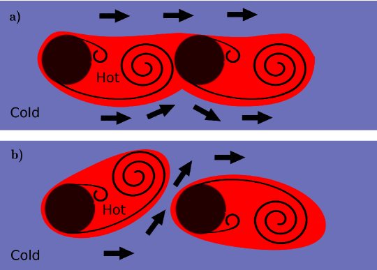
A schematic on how the flow pattern affect the heat exchange of the cylinders is reported in fig.14. The counter phase shedding causes the entrainment of cold fluid in the gap region enhancing the heat exchange of the downstream cylinder, on the contrary an in phase shedding avoid the entrainment of cold fluid leaving the downstream cylinder immersed in a hot region. At the downstream cylinders () shed vorticity in phase otherwise at a counter phase shedding can be distinguished (see fig.6). Otherwise, the cylinder has an in phase shedding at and a counter phase shedding at . Accordingly the measured values of the Nusselt number for each cylinder (fig.17) confirms the relation between vorticity pattern and the heat exchange.
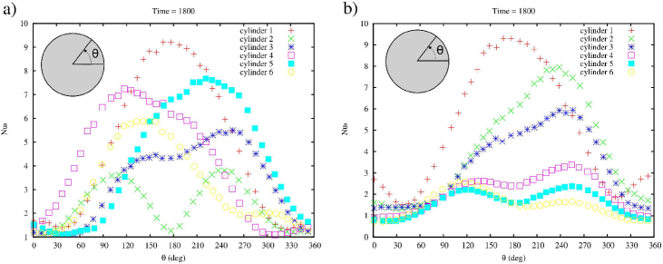
Figure15 shows the spatial distribution of the Nusselt number around the cylinders at and . Even if it represents only a snapshot of an unsteady behaviour, it remarks the asymmetric spatial distribution of the local Nusselt number according to the oscillatory flow field. At , fig.15a, the Nusselt number distribution shows that the cylinders , , and have an alternate position of the maximum on the cylinder surface. Whereas at , fig.15b, the maxima of the local Nusselt number are located in the same position.
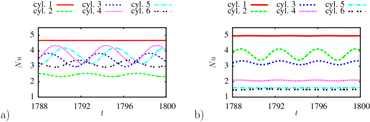
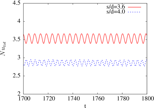
Thus, the vortices affect the heat transfer mechanisms on the cylinders due to their ability to carry cold fluid near the cylinders. According to the vortex shedding the heat exchange conditions change, therefore the time series of the mean Nusselt number experience an oscillating behaviour too, as showed in fig.16 (fig.16a at s/d = 3.6, fig.16b at s/d = 4). In figure 16 the Nusselt number of the cylinder is almost constant for both the spacings. The cylinder has a higher Nusselt number for because of the entrainment of cold fluid due to its counter phase shedding respect to cylinder , otherwise at the vorticity pattern avoid the entrainment of cold fluid decreasing the its heat exchange with the surrounding fluid. For the following cylinders, from to , continue to decrease their Nusselt number monotonically according to the in phase vortex shedding. Decreasing the spacing ratio at , the Nusselt number of cylinder increases its value respect to cylinder . Also the following cylinders keep their values significantly higher than the case with according to the counter phase vortex shedding that causes cold fluid entrainment in the gap regions.
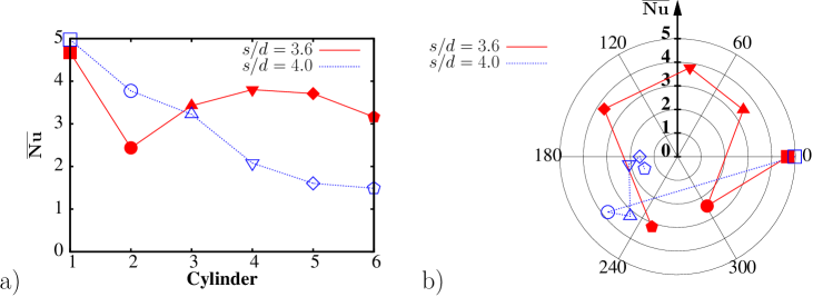
Although the instantaneous temperature and flow distributions are useful in the qualitative description of the phenomenon, in order to characterize this problem, an analysis on the time-average quantities is needed. Figure 16a shows the time average Nusselt numbers of each cylinder for and . Figure 17a confirms that there is the transition in the heat transfer of the cylinder array between a spacing ratio of and . For each time series of the Nusselt number, the main frequency and the phase shift, respect to the first cylinder phase, have been found. The results are reported in fig.17b in a polar diagram where the distance from the origin represents the mean Nusselt, whereas the angular position is the phase shift respect to the first cylinder. In order to measure the phase shifts, we verified that all the cylinders have the same main frequency. According to the power spectra of the mean Nusselt number of each cylinder, the heat transfer signal has one main frequency equal to and for a value of the spacing ratio of and , respectively. Looking at the time series of the mean Nusselt number for each cylinder, fig.16 and fig.17b, qualitatively, the phase shift between the different signals seems to vanish changing the spacing ratio from to . The phase shifts at are homogeneously distributed in the polar diagram respect to , for which the most part of the cylinders has the same phase shift. It suggests that the phase shifts of the mean Nusselt number can be related to the heat exchange efficiency. Indeed this results find a theoretical approach about the mechanism of counter phase shedding: the counter phase shedding causes a phase shift of the mean Nusselt number, while an in phase shedding leads to a zero phase shift of the mean Nusselt number. It is worth noting that the for a spacing ratio of is about higher than those at a spacing ratio of (fig.18).
V Conclusions
The numerical simulations of the flow around six in-line iso-thermal circular cylinders at for two values of the spacing ratio ( and ) is presented. Between the spacing ratios and a flow pattern transition is found. Long term and large domain simulations reveals at both the spacing ratio ( and ) there are a main frequency and one high secondary frequency in the amplitude spectra of the lift coefficient. In particular, for a spacing ratio of , one low secondary frequency has been found near the cylinder (see fig.10). This lowest secondary frequency depends on a secondary vortex street in the far wake region.
Two new flow modes are classified for six in-line circular cylinders configuration at a . Stable shear layer (SSL) mode and shear layer secondary vortices (SLSV) mode. The former occurs at spacing ratio, where the shedding vortices coming from the downstream cylinder merge in two stable parallel shear layer rows that are dissipated due to viscosity. At a spacing ratio of the flow is organized in the SLSV mode for which the shear layers become unstable in the far wake region producing a secondary vortex street. The SLSV mode provides clear evidence that the drag is reduced up to with respect SSL mode.
The overall heat exchange is heavily affected by the spacing ratio at the transition. In fact, at spacing ratio, the flow pattern induces the mixing of cold flow near the heated cylinders , , and increasing their local Nusselt numbers respect to the case at a spacing ratio of . For the same reason, cylinder has an higher Nusselt number for a spacing ratio of respect to the case. The oscillating dynamics of the time series of the local Nusselt number states that the higher phase shift between the different cylinder, the higher heat exchange on the cylinder is. It is worth noting that the overall heat exchange increase of reducing the spacing ratio from to .
VI Ackonwledgement
We acknowledge the kind support provided by the IT staff (M. Franza, A. Chiffi, S. Sergiampietri, E. Rizzo) of the “Centro Cultura Innovativa d’Impresa”, University of Salento (Italy), where the computations were carried out.
References
- Ali Kosar and Peles, (2005) Ali Kosar, C. M. and Peles, Y. (2005). Laminar flow across a bank of low aspect ratio micro pin fins. Journal of Fluids Engineering, 127(3):419–430.
- Bao et al., (2012) Bao, Y., Wu, Q., and Zhou, D. (2012). Numerical investigation of flow around an inline square cylinder array with different spacing ratios. Computers & Fluids, 55(0):118 – 131.
- Ben Meftah and Mossa, (2013) Ben Meftah, M. and Mossa, M. (2013). Prediction of channel flow characteristics through square arrays of emergent cylinders. Physics of Fluids, 25:045102.
- Carmo et al., (2010) Carmo, B. S., Meneghini, J. R., and Sherwin, S. J. (2010). Secondary instabilities in the flow around two circular cylinders in tandem. Journal of Fluid Mechanics, 644:395–431.
- Chan et al., (2011) Chan, A. S., Dewey, P. A., Jameson, A., Liang, C., and Smits, A. J. (2011). Vortex suppression and drag reduction in the wake of counter-rotating cylinders. Journal of Fluid Mechanics, 679:343–382.
- Chatterjee et al., (2009) Chatterjee, D., Biswas, G., and Amiroudine, S. (2009). Numerical investigation of forced convection heat transfer in unsteady flow past a row of square cylinders. International Journal of Heat and Fluid Flow, 30(6):1114–1128. cited By (since 1996)8.
- Ding et al., (2007) Ding, H., Shu, C., Yeo, K. S., and Xu, D. (2007). Numerical simulation of flows around two circular cylinders by mes h-free least square-based finite difference methods. International Journal for Numerical Methods in Fluids, 53:305–332.
- Fornarelli and Vittori, (2009) Fornarelli, F. and Vittori, G. (2009). Oscillatory boundary layer close to a rough wall. European Journal of Mechanics - B/Fluids, 28(2):283 – 295.
- Hanson and Ziada, (2011) Hanson, R. and Ziada, S. (2011). Effect of acoustic resonance on the dynamic lift of tube arrays. Journal of Fluids and Structures, 27(3):367–382.
- Harimi and Saghafian, (2012) Harimi, I. and Saghafian, M. (2012). Numerical simulation of fluid flow and forced convection heat transfer from tandem circular cylinders using overset grid method. Journal of Fluids and Structures, 28:309–327.
- Jester and Kallinderis, (2003) Jester, W. and Kallinderis, Y. (2003). Numerical study of incompressible flow about fixed cylinder pairs. Journal of Fluids and Structures, 17(4):561 – 577.
- Kloker et al., (1993) Kloker, M., Konzelmann, U., and Fasel, H. (1993). Outflow boundary conditions for spatial navier-stokes simulations of transition boundary layers. AIAA journal, 31(4):620–628.
- Li et al., (1991) Li, J., Chambarel, A., Donneaud, M., and Martin, R. (1991). Numerical study of laminar flow past one and two circular cylinders. Computers & Fluids, 19(2):155 – 170.
- Liang et al., (2009) Liang, C., Papadakis, G., and Luo, X. (2009). Effect of tube spacing on the vortex shedding characteristics of laminar flow past an inline tube array: A numerical study. Computers & Fluids, 38(4):950 – 964.
- Lo and Su, (2012) Lo, D. and Su, D.-T. (2012). An embedding finite element analysis of heat transfer on the surface of circular cylinders in flow. International Journal of Heat and Mass Transfer, 55(23-24):6916–6926.
- Lu et al., (2012) Lu, J., Han, H., and Shi, B. (2012). A numerical study of fluid flow passes two heated/cooled square cylinders in a tandem arrangement via lattice boltzmann method. International Journal of Heat and Mass Transfer, 55(15â16):3909 – 3920.
- Mahír and Altaç, (2008) Mahír, N. and Altaç, Z. (2008). Numerical investigation of convective heat transfer in unsteady flow past two cylinders in tandem arrangements. International Journal of Heat and Fluid Flow, 29(5):1309–1318.
- Park et al., (1998) Park, J., Kwon, K., and Choi, H. (1998). Numerical solutions of flow past a circular cylinder at reynolds numbers up to 160. KSME International Journal, 12 (6):1200 – 1205.
- Popinet, (2003) Popinet, S. (2003). Gerris: a tree-based adaptive solver for the incompressible euler equations in complex geometries. Journal of Computational Physics, 190(2):572–600.
- Popinet, (2009) Popinet, S. (2009). An accurate adaptive solver for surface-tension-driven interfacial flows. Journal of Computational Physics, 228:5838–5866.
- Prasanth and Mittal, (2009) Prasanth, T. and Mittal, S. (2009). Vortex-induced vibration of two circular cylinders at low reynolds number. Journal of Fluids and Structures, 25(4):731 – 741.
- Rinaldi and Païdoussis, (2012) Rinaldi, S. and Païdoussis, M. (2012). Theory and experiments on the dynamics of a free-clamped cylinder in confined axial air-flow. Journal of Fluids and Structures, 28:167–179.
- S. Mittal and Kumar, (2001) S. Mittal, R. and Kumar, V. (2001). Flow-induced oscillations of two cylinders in tandem and staggered arrangements. Journal of Fluids and Structures, 15(5):717 – 736.
- Sewatkar et al., (2012) Sewatkar, C. M., Patel, R., Sharma, A., and Agrawal, A. (2012). Flow around six in-line square cylinders. Journal of Fluid Mechanics, 710:195–233.
- Sharman et al., (2005) Sharman, B., Lien, F. S., Davidson, L., and Norberg, C. (2005). Numerical predictions of low reynolds number flows over two tandem circular cylinders. International Journal for Numerical Methods in Fluids, 47(5):423–447.
- Sreedharan et al., (2008) Sreedharan, S. S., Tafti, D. K., Rozati, A., and Blackwell, N. E. (2008). Heat-mass transfer and friction characteristics of profiled pins at low reynolds numbers in minichannels. Numerical Heat Transfer Part A-applications, 54:130–150.
- Sumner et al., (2000) Sumner, D., Price, S. J., and Paidoussis, M. P. (2000). Flow-pattern identification for two staggered circular cylinders in cross-flow. Journal of Fluid Mechanics, 411:263–303.
- Wang et al., (2010) Wang, S. Y., Tian, F. B., Jia, L. B., Lu, X. Y., and Yin, X. Z. (2010). Secondary vortex street in the wake of two tandem circular cylinders at low reynolds number. Phys. Rev. E, 81:036305.
- Ziada and Oeng̦ren, (1992) Ziada, S. and Oeng̦ren, A. (1992). Vorticity shedding and acoustic resonance in an in-line tube bundle part i: Vorticity shedding. Journal of Fluids and Structures, 6(3):271 Р292.