A compact, robust, and transportable ultra-stable laser with a fractional frequency instability of
Abstract
We present a compact and robust transportable ultra-stable laser system with minimum fractional frequency instability of at integration times between 1 to 10 s. The system was conceived as a prototype of a subsystem of a microwave-optical local oscillator to be used on the satellite mission STE-QUEST (Space-Time Explorer and QUantum Equivalence Principle Space Test, http://sci.esa.int/ste-quest/). It was therefore designed to be compact, to sustain accelerations occurring during rocket launch, to exhibit low vibration sensitivity, and to reach a low frequency instability. Overall dimensions of the optical system are . The acceleration sensitivities of the optical frequency in the three directions were measured to be , , and , and the absolute frequency instability was determined via a three-cornered hat measurement. The design is also appropriate and useful for terrestrial applications.
.1 Introduction
Satellites on selected orbits in Space is possible to experience a long-duration of free-fall condition, a varying distance to Earth (or to other planets), a varying speed, or a varying line of sight to the satellite. These conditions make Space an ideal place to carry out certain precision experiments, in particular for testing fundamental notions of space and time Ashby et al. (2009); Schiller et al. (2009); Wolf et al. (2009); the ; Schiller et al. (2012); Altschul et al. (2014). For example, atomic clocks, including optical clocks, are proposed to be operated in Space for testing the gravitational time dilation or the Shapiro effect. In such missions, ultra-stable lasers are foreseen to be used as the local oscillators to interrogate the atomic transitions.
A laser with ultra-stable frequency is obtained by locking the laser frequency to the resonance of a high-finesse cavity, which makes the fractional frequency instability of the laser equal to the cavity’s fractional length instability . This latter instability is in practice limited by several factors: the Brownian thermal noise of the cavity, the temperature instability, and the mechanical instability (influenced by environmental seismic and acoustic accelerations) of the setup. Usually, in the laboratory, in order to reduce the influence of the unavoidably present acceleration noise to the cavity, the cavity is laid on optimized supporting points Nazarova et al. (2006); Webster et al. (2007); Millo et al. (2009), which makes the whole apparatus not easily transportable. For transportable setups, the cavities need to be mechanically locked during transportation or need to be squeezed in a supporting structure Vogt et al. (2011). In this case deformations of the supporting structure also deform the cavity and increase its acceleration sensitivities. In order to reduce this effect, cavities are designed with special, optimized shapes and squeezed at a particular angle Webster and Gill (2011); Leibrandt et al. (2011a). Using such squeeze-insensitive designs, cavities can be operated in non-laboratory environments Leibrandt et al. (2011b). However, these designs employ approximately cubic cavity shapes which implies that the cavity volume increases by a factor , if the cavity length is increased, which is necessary e.g. in order to reduce its thermal noise. Moreover, it is unclear whether the mountings developed so far are robust enough to withstand a rocket launch, a necessary condition for use of the cavity in space. Cavity designs aimed at satisfying this requirement have been developed Folkner et al. (2010); Argence et al. (2012) which comprise a complex mechanical layout which rigidly mounts the cavity and at the same time decouples it from acceleration induced deformations of the supporting structure.
In the present publication, we report on another candidate design for a space cavity, which uses independent separate rigid mountings for the each of the three translational degrees of freedom, each acting in the corresponding symmetry plane Sterr (2012). It is relatively simple in its implementation, and therefore should be of interest also for easily transportable terrestrial applications. Moreover, our design is applicable for long and slim cavities, which are thus relatively compact and lightweight. The system we present was developed for use together with a Nd:YAG laser, since commercial space-qualified Nd:YAG lasers with low free-running linewidth and small free-running absolute frequency drift are available (and have flown in space).
Specifically, within the concept of the STE-QUEST missionthe , the purpose of the frequency-stabilized Nd:YAG laser is to serve as an optical local oscillator. An erbium-doped fiber laser frequency comb will be used to convert the ultra-stable optical frequency into an ultra-stable microwave signal for interrogation of a cold cesium atomic clock. This microwave is specified with orders of magnitude lower phase noise and short-term frequency instability than the best space-qualified quartz oscillators.
.2 Design of the reference cavity
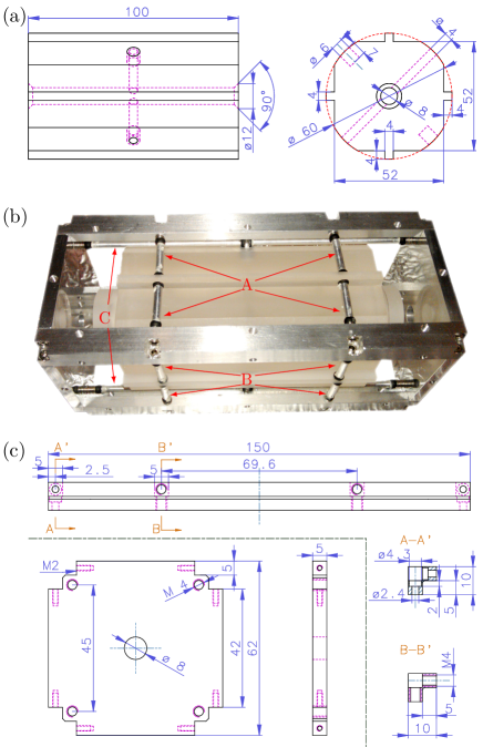
The design of the cavity spacer and support frame are shown in Fig. 1. The dimensions of the approximately cylindrical cavity spacer are 100 mm 60 mm (lengthdiameter). The detailed design of the cavity spacer is shown in Fig. 1 (a). The spacer is made from standard grade ULE glass. On each end of the spacer a fused silica mirror (ATFilms, Boulder 111This and other information on manufacturers is provided for technical communication purposes only and does not constitute an endorsement by the University of Düsseldorf or PTB.) is optically contacted. The purpose of using fused silica mirrors instead of ULE mirrors is to reduce the thermal noise Numata et al. (2004); Kessler et al. (2012) to a calculated instability flicker floor of . The radii of curvature of the mirrors are infinity and 1 m, respectively. The mirrors are 25.4 mm in diameter and 6 mm thick and are high-reflectivity-coated for 1064 nm, leading to a measured cavity linewdith of 3.7 kHz and finesse of 400 000. The central 6 mm diameter area of the back side is anti-reflection-coated for the same wavelength. On the back sides of the cavity mirrors, ULE rings (inner/outer diameter 9/25.4 mm, thickness 6 mm) are optically contacted to compensate the thermal expansion caused by the fused silica mirrors Legero et al. (2010).
The mounting of the cavity is based on the idea to separate the forces acting on the cavity along the optical axis and perpendicular to this direction. The resulting forces are then applied in the corresponding symmetry plane of the cavity. Thus, due to symmetry, to first order in the accelerations , the resonator length, i.e. the distance between the mirror centers, will not change Sterr (2012).
The mounting structure of the cavity is shown in Fig. 1 (b), The cavity is supported by squeezing 20 short posts with diameters of 3 mm pairwise on 10 points on the cavity spacer. These 20 posts are divided into 3 groups A, B, and C in Fig. 1 (b). The posts in a given group are parallel to each other. Each group restricts the movement of the cavity in the direction parallel to the posts’ axes while it allows motion of the cavity in the two directions perpendicular to the posts’ axes. For motional constraint in the two directions orthogonal to the cavity axis (groups A and B), 4-post pairs are used for each direction. 2-post pairs are used in order to limit the movement of the cavity along its axis (group C). The distance along the cavity axis between the supporting points in groups B and C are 69.6 mm and they are located symmetrically with respect to the midplane of the cavity which is perpendicular to its axis. The supporting points of group C are on this symmetry plane of the cavity and act on invar pins that are glued into the ULE pacer. The positions of the supporting points were optimized by using finite element simulation Millo et al. (2009); Chen et al. (2006). M4 set screws on the frame are used to press the posts to the cavity. Viton balls (diameter 4 mm) are inserted between the screws and the posts to reduce the tangential restoring force of the posts. Viton balls cut in half are inserted between the cavity and the posts so as to increase friction and further decouple the cavity from the supporting frame. The mechanical drawing of the supporting frame is shown in Fig. 1 (c).
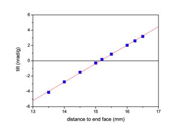
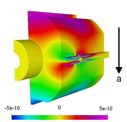
Effects still to consider are deviations from symmetry, e.g. from an offset of the mode axis from the geometrical symmetry axis in combination with acceleration induced bending of the spacer. This bending can be minimized by appropriate positions of the mounting. This was simulated by FEM models elm (Fig. 2) to identify the mounting points with the smallest bending (see Fig. 3). Assuming a 1 mm deviation of the resonator mode from the cavity’s geometric symmetry axis, a deviation of the mounting position of 0.5 mm from the optimum position would lead to a sensitivity of /. Deformation from squeezing the rim at the mounting positions can also couple accelerations to length changes. The FEM simulations indicate a value of for a squeezing force of 1 N. To provide reliable holding under a design acceleration of , the squeezing force of the mounting needs to be sufficiently large. For a perfectly linear elastic material, the squeezing force needs to balance the maximum reaction force. In our case this would require, for each of the four points in each direction, a squeezing force of 15 N. However, the large-range behavior of viton balls is strongly nonlinear, with the force increasing to the power 3/2 with approach Tatara (1991); Tatara et al. (1991). This reduces the required squeezing force by 30% to 10 N. Implementing a higher nonlinearity, e.g. by optimized shape of the viton parts, the squeezing force and related deformation can even be further reduced.
Imperfections on the mount can lead to forces tangential to the mounting plane. On the rim opposite axial forces of 1 N on each pad result in m or and radial forces of 1 N at each pad lead to m or via the Poisson effect. With the cavity mass of 600 g at acceleration, a total normal force of 6 N needs to be taken up by the supports in group A or B, so these tangential forces need to be less than of the normal force for a total sensitivity less than /.

.3 Cavity subsystem description
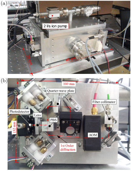
The cavity is operated in a vacuum chamber (VaC) inside two thermal shields. The inner shield is formed by four polished aluminum side covers (4 mm thick, not shown in the figures) that are fixed to the support frame. This assembly is mounted inside the outer thermal shield (TS) by screws and thermally isolating ceramic washers. This outer thermal shield is mounted on 4 thermoelectric cooling elements (TEC) on the bottom of the vacuum chamber using indium foils to insure good thermal contact between the TECs and the thermal shield and the chamber. The TECs allow to actively stabilize the temperature of the outer thermal shield to the zero coefficient-of-thermal-expansion (CTE) temperature of the cavity, which was determined to be near 0 ∘C by measuring the frequency of the cavity when set to different temperatures. Remaining temperature fluctuations of the outer shield are additionally filtered by the inner heat shield, leading to an overall second-order low-pass behavior between the outer shield and the cavity. On long time scales its behavior is described by a time constant of 5.5 hours, which was determined by measuring the the laser frequency change after a step of the outer shield temperature. To further improve the temperature stability, also the temperature of the vacuum chamber is actively stabilized at 20 ∘C. All temperature sensors are standard 10 k thermistors and PID control circuits are used to stabilize the temperatures. The in-loop temperature stability at the outer thermal shield is about 1 mK. The vacuum in the chamber is kept to mbar by a miniature 2 l/s ion pump (Gamma Vacuum).
.4 The optical system
A schematic of the complete system is shown in Fig. 4. A Nd:YAG laser (Innolight, Mephisto S) is frequency-modulated at 3 MHz (G2) via the piezo-actuator (PZT) of the laser. After an optical isolator, the laser beam is coupled to a single-mode fiber by an angled physical contact (APC) fiber collimator (FC, FC1). Using a fiber splitter (FS1) one part of the laser wave is sent to a compact optical breadboard, which is attached to the vacuum chamber Fig. 5 (a) and further coupled into the cavity. The detailed design of the compact breadboard is shown in Fig. 5 (b). The laser beam exiting from FC2 is diffracted by the acousto-optic modulator (AOM, Crystal Technology 3200-147). The first-order diffracted wave is coupled into the cavity. The polarizing beam splitter (PBS) and the quarter-wave plate are used to pick up the reflection from the cavity. The lens and the photo-detector PD1, mounted on a translation stage are used to detect the reflection from the cavity. The electric signal from the PD1 detector is frequency-mixed (by M1, Mini-Circuits ZAD-8) with the 3 MHz signal, phase-shifted (PS) with respect to the laser modulation signal to generate the error signal. It is filtered by two cascaded proportional-integral-derivative (PID) circuits with P-I corner frequencies of approximately 3 kHz and 10 kHz and P-D corner frequency of approximately 20 kHz and 30 kHz. The output of the locking circuits combined with the 3 MHz modulation by using a bias-T (Mini-Circuits ZFBT-4R2GW) and fed back to the PZT modulation input of the laser. The output from the second PID is also further integrated (INT) and sent to the temperature control modulation input (T) of the laser for long-term stabilization of the laser Chen et al. (2012). The transmission of the cavity is detected by another detector (PD2) attached to the other side of the vacuum chamber. This signal is used to stabilize the laser power circulating inside the cavity through feedback to the amplitude modulation input (AM) of the AOM driver (G1). The sensitivity of the frequency on the transmit power is about 100 Hz () per 1 %.
Four stepping motors (Nanotec SPG1518M0504-102) are attached to two of the mirror mounts (New Focus 9876), which may be used to optimize the beam coupling to the cavity when necessary and when there is no manual access to the optical setup, e.g., when during operation in space or at a location on Earth distant from the laboratory. The motors can therefore be omitted when the system is operated in a laboratory with manual access. During initial alignment of the small breadboard, a low-cost CCD camera is set up in transmission through the cavity, in order to identify the cavity modes.
The laser and the optical system are attached to a standard commercial optical breadboard (OB), and placed on an active-vibration-isolation system (AVI, Table-Stable AVI-400). This arrangement is used for testing and characterizing the system, and for operation on Earth. In space, the latter two components would be absent.
The overview of the system is shown in Fig. 5 (a). The outer dimensions of the system, without the laser, optical breadboard, and vibration isolation, are about mm3 (lengthwidthheight). The mass is approximately 10 kg.

.5 Characterization method
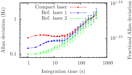
The frequency stability of the compact laser system is characterized by beating with two independent ultrastable Nd:YAG lasers whose frequencies are locked to two reference cavities with lengths of 30 cm. The frequency instability of each individual laser is then obtained by the three-cornered-hat method Gray and Allan (1974). The laser beam exiting FS1 (Fig. 4) is combined in the fiber splitter FS2 with the two beams from the two reference lasers. The combined beam exiting from FC3 is guided to a fast photo-detector PD3 (EOT ET-3000A), for detecting the three beat signals between the three laser waves. The beat signals (around 70, 480, and 550 MHz) were split into three ways by RFPS (RF power splitter, Mini-Circuits ZF3RSC-542-S+) and down-mixed by three independent synthesizers G3, G4, and G5 (HP 8656B, and phase-locked to the same 10 MHz reference) to approximately 10 MHz using mixers M2. Each signal was bandpass filtered at 10 MHz by BPS (bandpass filter, Mini-Circuits BBP-10.7+) and sent to a four-channel dead-time-free phase comparator MPC (K+K Messtechnik GmbH K+K FXE). The frequencies are recorded by a computer and analyzed to obtain the Allan deviations.
.6 Characterization results
We operate the cavity with 200 W entering the vacuum chamber. The coupling efficiency of the laser wave to the cavity is approximately 40 %. The bandwidth of the lock system is about 70 kHz. The system works very reliably and essentially never fell out of lock during several months of operation. The frequency instabilities of the compact laser and the two reference lasers, obtained simultaneously via the three-cornered-hat method are shown in Fig. 6. The lowest instability of the compact laser is for integration times of 1 to 10 s. It remains below for integration times up to 100 s. This performance satisfies the specification of the STE-QUEST mission ste which calls for this level for integration times up to 100 s.
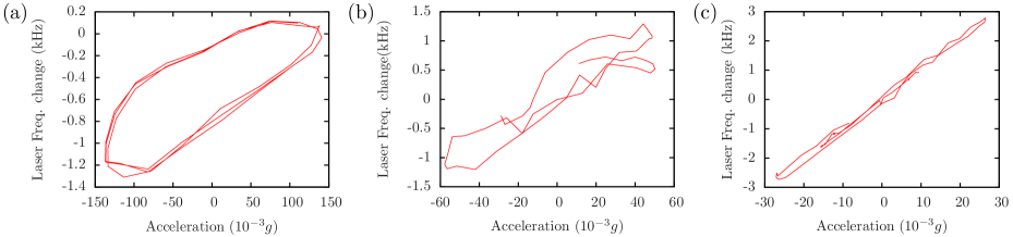
The acceleration sensitivity coefficients of the cavity are determined by recording acceleration level and beat frequency with respect to one reference laser, while shaking the system (optical system plus optical breadboard placed on AVI, which is supported by springs) sequentially in the three directions. The acceleration level is measured by an acceleration sensor (Wilcoxon research, model 731A) attached to the optical breadboard. The beat frequency is converted to a voltage by a frequency-to-voltage converter (home-built, based on a frequency-to-voltage converter chip, Texas Instruments VFC32KP). The output from the acceleration sensor and the frequency signal are simultaneously recorded by a digital-analog data acquisition card.
An acceleration along the vertical direction was excited by a voice coil actuator (home-built) attached to the optical table and to the optical breadboard and driven at a frequency close to the resonance of the overall system. The acceleration along the two horizontal directions were excited by manually hitting the optical breadboard on the side. From the test, shown in Fig. 7, we obtained acceleration sensitivities along the vertical, the horizontal across-cavity, and the axial directions of , , and , respectively.
For testing the robustness of the system, the system was carried, rotated and shaken by two persons holding it in their hands. The laser frequency remains stably locked to the cavity. The laser frequency change during this procedure is shown in Fig. 8. The frequency change is about 20 kHz when the cavity is rotated along the cavity axis by 90 degrees (starting at 12 s in the figure), and it is about 100 kHz when the cavity is oriented from the horizontal into the vertical direction (rotation occurs around the horizontal cross-axis, at 40 s). These frequency shifts are consistent with the sensitivities observed in Fig. 7. This test demonstrates that the cavity can be operated vertically or horizontally, and that the mounting concept is quite robust.
Because the cavity and the setup may experience a typical temperature variation from -20∘C to +50∘C during storage and transportation to space, a test of the robustness of the optical setup with respect to temperature variation was also done. The optical setup (without laser and with temperature stabilization switched off) was put in a refrigerator, cooled down to -30∘C, then warmed up to 50∘C with the TEC attached to the vacuum chamber, and finally back to room temperature. The coupling efficiency of the laser beam into the cavity changed from 40 % to 15 % during this temperature cycle. This means that the alignment was not “lost”; it was brought back to 40 % by adjusting just one mirror mount. This was done manually, but, as described above, can in the future also be done by remote control or an automatic routine, using the motorized mirror mounts in the small optical breadboard.
.7 Conclusion
In summary, we reported a robust mounting structure for high-finesse cavities, which represents a baseline design for a space unit. In addition, since it does not at present include any particularly sophisticated or expensive elements, the design is also suitable for laboratory use, and for non-laboratory, terrestrial environments. Applications are e.g. for a transportable optical clock or for a transportable, optically stabilized frequency comb. As an example of a useful application, in our laboratory we routinely use this system as an ultra-stable optical local oscillator to which a fiber frequency comb is locked that measures several other ultra-stable optical frequencies.
Acknowledgements.
This work was funded by the Bundesministerium für Wirtschaft und Technologie (Germany) under project no. 50OY1201 and the European Metrology Research Programme (EMRP) under IND14. The EMRP is jointly funded by the EMRP participating countries within EURAMET and the European Union.References
- Ashby et al. (2009) N. Ashby, P. L. Bender, J. L. Hall, J. Ye, S. A. Diddams, S. R. Jefferts, N. Newbury, C. Oates, R. Dolesi, S. Vitale, and W. J. Weber, Proceedings of the International Astronomical Union 5, 414 (2009).
- Schiller et al. (2009) S. Schiller, G. M. Tino, P. Gill, C. Salomon, U. Sterr, E. Peik, A. Nevsky, A. Görlitz, D. Svehla, G. Ferrari, et al., Exp. Astron. 23, 573 (2009).
- Wolf et al. (2009) P. Wolf, Ch. J. Bordé, A. Clairon, L. Duchayne, A. Landragin, P. Lemonde, G. Santarelli, W. Ertmer, E. Rasel, F. S. Cataliotti, et al., Exp. Astron. 23, 651 (2009).
- (4) The Space-Time Explorer and QUantum Equivalence principle Space Test (STE-QUEST), cosmic Vision 2015-2025, the future of ESA’s Science Programme, http://sci.esa.int/ste-quest/.
- Schiller et al. (2012) S. Schiller, A. Görlitz, A. Nevsky, S. Alighanbari, S. Vasilyev, C. Abou-Jaoudeh, G. Mura, T. Franzen, U. Sterr, and S. Falke, in European Frequency and Time Forum (EFTF), p. 412–418 (2012).
- Altschul et al. (2014) B. Altschul, Q. G. Bailey, L. Blanchet, K. Bongs, P. Bouyer, L. Cacciapuoti, S. Capozziello, N. Gaaloul, D. Giulini, J. Hartwig, et al., arXiv:1404.4307 (2014).
- Nazarova et al. (2006) T. Nazarova, F. Riehle, and U. Sterr, Appl. Phys. B: Lasers and Optics 83, 531 (2006).
- Webster et al. (2007) S. A. Webster, M. Oxborrow, and P. Gill, Phys. Rev. A 75, 011801 (2007).
- Millo et al. (2009) J. Millo, D. V. Magalhães, C. Mandache, Y. Le Coq, E. M. L. English, P. G. Westergaard, J. Lodewyck, S. Bize, P. Lemonde, and G. Santarelli, Phys. Rev. A 79, 053829 (2009).
- Vogt et al. (2011) S. Vogt, C. Lisdat, T. Legero, U. Sterr, I. Ernsting, A. Nevsky, and S. Schiller, Appl. Phys. B: Lasers and Optics 104, 741 (2011).
- Webster and Gill (2011) S. Webster and P. Gill, Opt. lett. 36, 3572–3574 (2011).
- Leibrandt et al. (2011a) D. R. Leibrandt, M. J. Thorpe, M. Notcutt, R. E. Drullinger, T. Rosenband, and J. C. Bergquist, Opt. Express 19, 3471–3482 (2011a).
- Leibrandt et al. (2011b) D. R. Leibrandt, M. J. Thorpe, J. C. Bergquist, and T. Rosenband, Opt. Express 19, 10278 (2011b).
- Folkner et al. (2010) W. M. Folkner, G. deVine, W. M. Klipstein, K. McKenzie, D. Shaddock, R. Spero, R. Thompson, D. Wuchenich, N. Yu, M. Stephens, et al. Laser Frequency Stabilization for GRACE-II, Earth Science Technology Forum, (Arlington, VA, United States, 2010), http://hdl.handle.net/2014/41635.
- Argence et al. (2012) B. Argence, E. Prevost, T. Lévèque, R. Le Goff, S. Bize, P. Lemonde, and G. Santarelli, Opt. Express 20, 25409 (2012).
- Sterr (2012) U. Sterr, Frequenzstabilisierungsvorrichtung, German Patent number DE102011015489 B3 (2012).
- Numata et al. (2004) K. Numata, A. Kemery, and J. Camp, Phys. Rev. Lett. 93, 250602 (2004).
- Kessler et al. (2012) T. Kessler, T. Legero, and U. Sterr, J. Opt. Soc. Am. B 29, 178 (2012).
- Legero et al. (2010) T. Legero, T. Kessler, and U. Sterr, J. Opt. Soc. Am. B 27, 914–919 (2010).
- Chen et al. (2006) L. Chen, J. L. Hall, J. Ye, T. Yang, E. Zang, and T. Li, Phys. Rev. A 74, 053801 (2006).
- (21) Elmer - finite element software for multiphysical problems, http://www.csc.fi/elmer/index.phtml.
- Tatara (1991) Y. Tatara, ASM J. Eng. Mater. Technol. 113, 285 (1991).
- Tatara et al. (1991) Y. Tatara, S. Shima, and J. C. Lucero, ASM J. Eng. Mater. Technol. 113, 292 (1991).
- Chen et al. (2012) Q. F. Chen, A. Nevsky, and S. Schiller, Appl. Phys. B: Lasers and Optics 107, 679 (2012).
- Gray and Allan (1974) J. E. Gray and D. Allan, in 28th Annual Symposium on Frequency Control, p. 243–246 (1974), http://tf.nist.gov/general/pdf/57.pdf.
- (26) STE-QUEST assessment study report (yellow book), reference: ESA/SRE(2013)6, http://sci.esa.int/ste-quest/53445-ste-quest-yellow-book/.