Liquid ropes: a geometrical model for thin viscous jet instabilities
Abstract
Thin viscous fluid threads falling onto a moving belt behave in a way reminiscent of a sewing machine, generating a rich variety of periodic stitch-like patterns including meanders, W-patterns, alternating loops, and translated coiling. These patterns form to accommodate the difference between the belt speed and the terminal velocity at which the falling thread strikes the belt. Using direct numerical simulations, we show that inertia is not required to produce the aforementioned patterns. We introduce a quasi-static geometrical model which captures the patterns, consisting of three coupled ODEs for the radial deflection, the orientation and the curvature of the path of the thread’s contact point with the belt. The geometrical model reproduces well the observed patterns and the order in which they appear as a function of the fall height.
pacs:
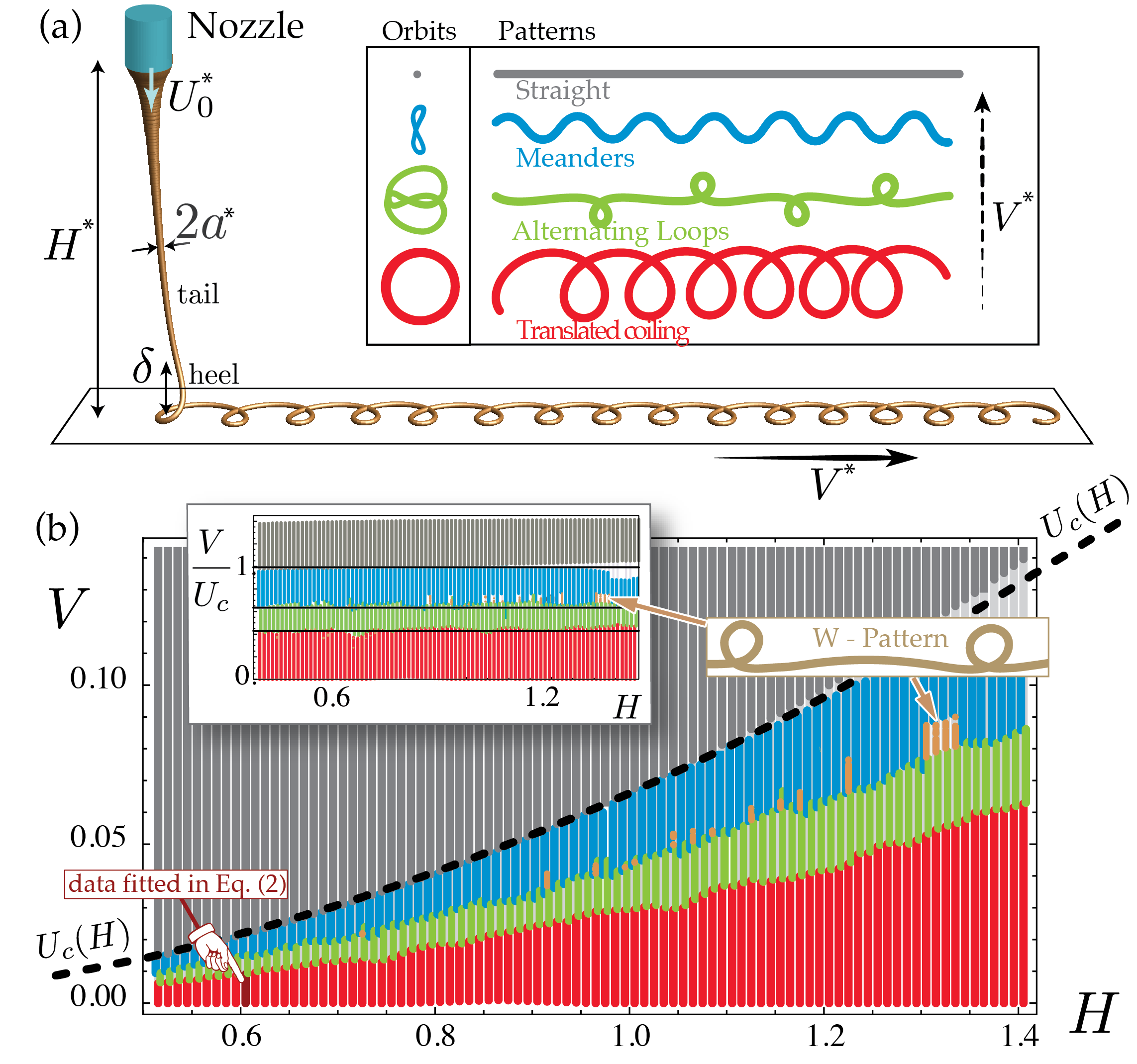
47.54.-r, 47.20.-k, 47.85.Dh, 46.32.+xA thin thread of viscous fluid falling onto a moving belt is a remarkable pattern-forming system with surprisingly complex behavior. The patterns laid down onto the belt include meanders, alternating loops, W-pattern, coiling (Fig. 1),
as well as various resonant patterns such as double coils and double meanders ChiuWebster:2006jd ; Morris . The resemblance of these patterns to the stitch patterns of a sewing machine led ChiuWebster:2006jd to call the system the “fluid mechanical sewing machine” (FMSM). The FMSM is of interest as a simplified model for industrial processes such as the production of non-woven textiles Marheineke:2009kp and the laying down of “squiggles” of icing on cakes. It is also an accurate model for one of the characteristic gestures of Jackson Pollock’s action painting, in which paint from a moving brush dribbles onto a stationary horizontal canvas Herczynski:2011ws . But the FMSM also has fundamental interest as an example of great complexity (roughly a dozen distinct patterns) arising in an extremely simple system (a single thread of Newtonian fluid). This fundamental interest has inspired several experimental, theoretical and numerical studies of the FMSM in recent years ChiuWebster:2006jd ; Morris ; Audoly:2012wk ; Brun:2012ic .
The FMSM patterns are best thought of as resulting from the lateral advection of the periodic orbits (in the frame of the nozzle) of the thread’s contact point with the belt. The canonical example of such a periodic orbit is the circular orbit produced by the steady coiling of a highly viscous fluid thread (e.g., honey) falling onto a surface (e.g., toast). It has been observed that the frequencies of the FMSM pattern are all simple multiples of the steady coiling frequency Brun:2012ic . In this Letter we reveal the unforeseen physical mechanism underlying this result, and show that it differs fundamentally from the typical harmonic resonance in parametric oscillators such as Mathieu’s which, in terms of frequency content, has strong similarities with the alternating loop pattern Brun:2012ic . The novel aspect of the system we study resides in the fact that no inertia is needed to produce the patterns. Accordingly, we account for the observations using a simple three-variable dynamical system for the radial deflection, the orientation and the path curvature of the contact point.
Before deriving the model we perform direct simulations of the FMSM with the Discrete Viscous Rods algorithm (DVR) Audoly:2012wk ; Brun:2012ic to propose a rationalization of the FMSM phase diagram when inertia is negligible. Consider a thread with kinematic viscosity falling at a volumetric rate from a nozzle of dimensional height onto a conveyor belt moving horizontally at speed . The thread is stretched by gravity (denoted ) during its fall so that the speed of the fluid increases with distance from the nozzle. Balancing the gravitational stretching with the viscous dissipation in the thread yields a typical length scale and time scale that we use to nondimensionalize our equations. In particular, and are the dimensionless height of fall and the dimensionless belt velocity respectively. Varying these two parameters independently allows us to generate a phase diagram for the FMSM Brun:2012ic . In such a diagram, inertial effects are generally negligible when working with physical parameters such that . Herein, we make the choice of working with the typical parameter values used in the literature Morris such that , but we artificially omit inertia in our numerical simulations. The purpose is to identify the patterns which survive this quasi-static limit and show that nonlinearities in this system are independent of inertia. The patterns (Fig. 1) which we found are detailed next.
When the belt has velocity the thread coils steadily with a radius , frequency and speed (steady coiling) Ribe:2012uo . When gradually increasing the belt velocity while keeping other parameters constant, the coiling pattern is first simply translated on the belt (translated coiling) up to a certain critical value of where loops form alternatively on one side of the belt and then the other (alternating loops). For higher belt speeds the thread exhibits some meanders Ribe:2006gz ; Blount:2011ke which collapse to a straight line for a critical value of the belt velocity . For velocities higher than the thread has a catenary shape and its contact point with the belt is stationary in the laboratory frame. In the rest of the Letter we concentrate on belt speeds in the range . Three points are of particular interest. First, no double patterns Brun:2012ic such as the double coiling or double meanders were found in these quasi-static conditions. This was anticipated since such resonant patterns are typically observed for large values of where inertia is dominant in normal conditions Brun:2012ic . Second, we found hysteresis in the critical belt velocity values corresponding to the transition between patterns. The data shown in Figure 1b correspond to the situation where the belt was slowly accelerated. The case of a decelerating belt is discussed at the end of the Letter. Third, we report the presence of another pattern — the W-pattern — which we found in limited portions of the diagram (see overlay in Fig. 1b). It appears in competition with the meanders after the alternating loops become unstable when the belt speed is increased (and only then).
For any height , we can compute the steady coiling velocity using the method of Ribe-Coiling-of-viscous-jets-2004 . This yields the dashed curve in Fig. 1b. The curve matches the lower boundary of the grey region (straight pattern), which reveals that the onset of steady coiling matches accurately the critical velocity . The central role played by the reduced velocity in the formation of the patterns becomes even more evident when one plots the phase diagram in terms of , see inset in Fig 1b: then, all boundaries between patterns become horizontal straight lines. This important finding shows that the only influence of the height of fall on the patterns is to set the value of the reduced velocity : the patterns can be rationalized strictly in terms of the parameter .
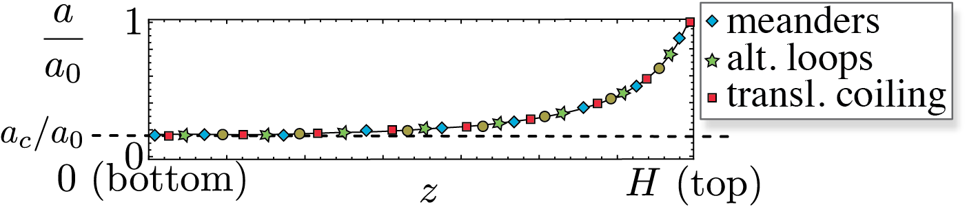
The reason why is the only relevant parameter may be understood by analyzing the thread’s radius profile for different while keeping constant, i.e. moving vertically in the phase diagram and browsing through the different patterns. We do so in Fig 2 and find that all the curves collapse onto a single master curve. In the upper part of the master curve, called the tail, the thread is accelerated and stretched by gravity until it reaches a terminal radius . Both this radius and the speed at which the thread arrives on the belt are found to be approximately independent of in the range . As a consequence the thread speed may be called the free-fall speed ChiuWebster:2006jd and is equal to the coiling speed (observed when ) which solely depends on . In general and do not match and there is a small region near the lower end of the thread, called the heel in Fig.1, where the thread bends and twists while keeping a constant radius. The patterns are produced as the heel is set in motion to satisfy the no-slip boundary condition at the contact point between thread and belt:
| (1) |
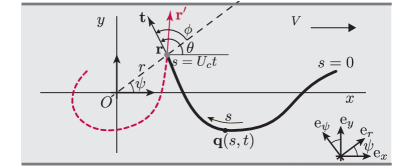
Here we use the notation introduced in Fig. 3: is the unit tangent to the thread at the point of contact with the belt, is the velocity in the laboratory frame of this non-material point, and is a unit vector in the direction of belt motion. The limiting case of steady coiling corresponds to and , and the case of a straight (catenary) pattern corresponds to , and . In the general case , the speed at which the thread arrives at the belt exceeds the belt’s ability to carry it away in a straight line ( in equation above). This excess length of thread is accumulated on the belt in the form of patterns produced as the heel lays down on the belt. This agrees with our initial observation that the critical velocity at which the straight pattern appears is , see Fig 1b.
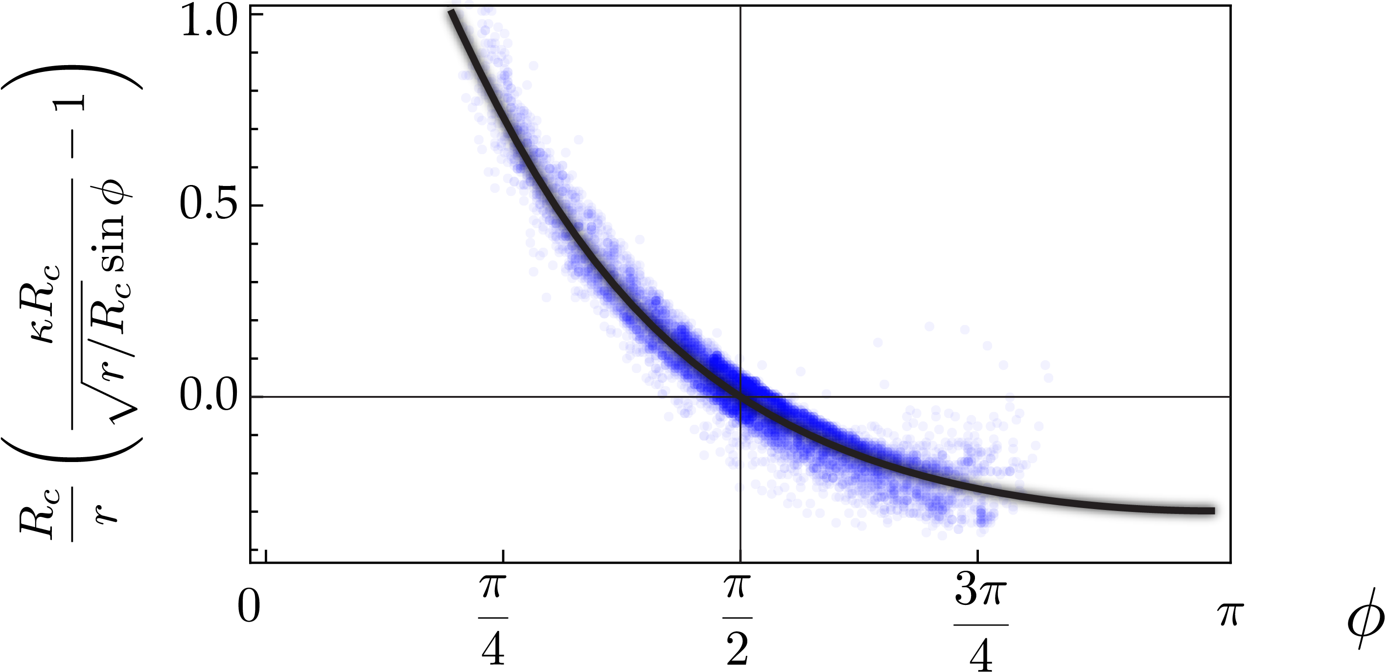
We now turn to the task of characterizing and then modeling the heel boundary layer where the deposition takes place. Since bending stresses are dominant in the heel, we anticipate that the curvature of the thread at the point of contact plays a key role in the pattern formation. Working in the quasi-static (inertialess) limit, we assume that the shape of the hanging thread (and in particular its curvature near the point of contact) is only a function of the current boundary conditions applied to the thread. The boundary conditions at the nozzle are time-invariant as the fall height and flow rates are fixed. Therefore, we view the curvature at the bottom of the hanging thread as a function of the position of the point of contact and the orientation of the tangent . The equations for the hanging thread are cylindrically invariant, and therefore we have , where is the direction of the tangent relative to the line joining the projection of the nozzle to the point of contact (Fig. 3). The function is found by fitting DVR simulations of translated coiling for the case and (darker red bar in the lower left corner of figure 1b). As explained in the Supplemental Information, time series of for the translated coiling pattern are well approximated by the heuristic fit
| (2) |
where and and is the radius of steady coiling Ribe:2012uo . Fig 4 shows the collapse of the numerical data obtained from Eq. (2).
Building on our previous observations, we now derive a quasi-static geometric model for the formation of the trace. The heel is modeled as a filament of uniform radius falling towards the belt at a velocity , which is bent and laid down quasi-statically onto the belt. Let be the arc-length along the trace, with corresponding to the point which contacted the moving belt at time and corresponding to the current point of contact . We label material points in the trace by their (Lagrangian) coordinate . We also use as a time-like variable and write for the contact position at time . Let be the position on the belt of the point at time , with . This point was deposited at time at position , and has subsequently been advected at velocity by the belt. Thus
| (3) |
In our model of the thread, the dynamical quantities of interest are the contact position , and the tangent vector and curvature at the point of contact. At any point , the tangent to the trace is . In particular, at the point of contact , and we recover Eq. (1) with . Now let denote the polar coordinates of the contact point as shown in Fig. 3, and let denote the angle from the -axis to . We resolve , and into the polar basis , and use to eliminate the dependence on :
| (4a) | ||||
| (4b) | ||||
| Finally, is the curvature of the trace at the contact point, which has been found in Eq. (2) in terms of a fitting function : | ||||
| (4c) | ||||
Equations (4a–4c) are a set of coupled ordinary non-linear differential equations for the functions , and , depending on a single dimensionless parameter — the parameter in equation (2) sets a lengthscale for and , and can be removed by rescaling. We refer to this system of differential equations as the geometrical model (GM). The kinematic equations (4a–4b) capture the coupling with the moving belt, while equation (4c) captures the shape of the hanging thread as set by the balance of viscous forces and gravity. We integrated the GM numerically, varying the velocity parameter in the range (Fig 5). The solutions were found to settle into periodic orbits, see Fig. 5a.
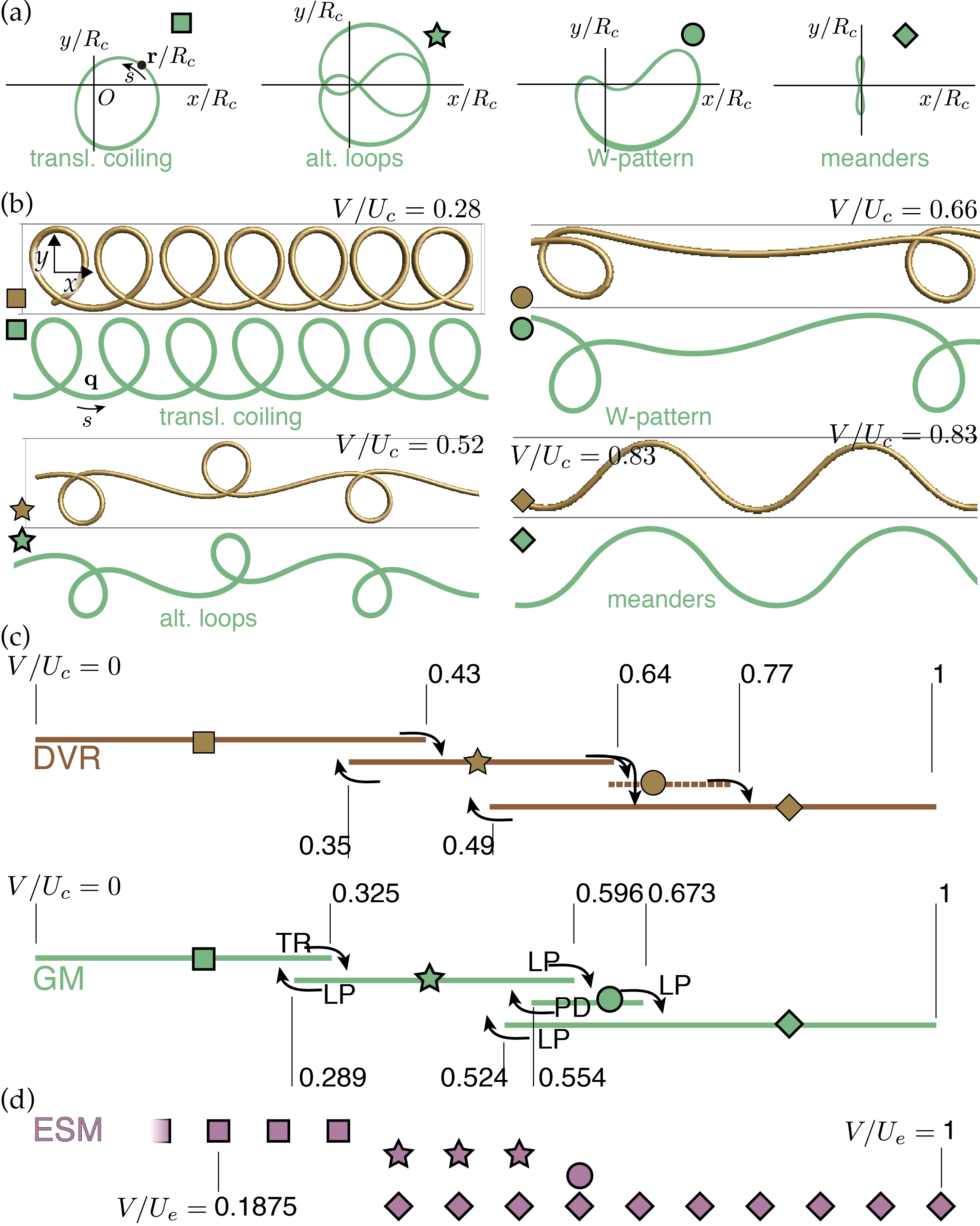
The patterns corresponding to the different orbits can be identified by reconstructing the complete trace from Eq. (3), and then compared to those obtained by DVR simulations, see Fig. 5b. With the aim to calculate the bifurcation thresholds accurately and to identify the nature of the bifurcations, we also investigated the stability domains of the periodic solutions of the GM using the continuation software AUTO 07p Doedel , see Fig. 5c.
All the patterns originally observed with DVR in the quasi-static (non-inertial) limit are captured by the GM. They appear in the correct order when is varied, and there is a good agreement on the values of the pattern boundaries, see Fig. 5c. Their shapes are accurately captured as well, see Fig. 5b. Alternating loops and meanders are symmetric about in their full domain of existence, both in DVR simulations and in the GM. The alternating loops, and the amplitude of meanders both decrease as the belt velocity increases and the latter tends to zero when , as expected. Coils are symmetric at zero belt velocity, but then turn asymmetric at larger velocities. W-patterns are, on the other hand, always asymmetric.
Interestingly, the GM sheds light on two subtle features of the FMSM. First, it accounts for the hysteresis observed in DVR when transitions between patterns occur at different values depending on whether the belt velocity is increasing or decreasing: the domains of stability of the various patterns predicted by the GM do indeed overlap, see Fig. 5c. Second, it explains why the W-pattern can be observed in DVR with an increasing belt velocity, but not with a decreasing one. Indeed, the layout of the stability diagram of the GM in Fig. 5c predicts that meanders will destabilize directly into alternated loops for a decreasing belt velocity, skipping the W-pattern.
We now examine the relevance of the GM to the elastic sewing machine, made up of an elastic thread fed downwards onto a belt moving at a speed . This system has been analyzed by a combination of methods including experiments, direct numerical simulations, and scaling arguments Habibi:2011jr ; Bergou-Wardetzky-EtAl-Discrete-Elastic-Rods-2008 ; Jawed-Da-EtAl-Coiling-of-elastic-rods-2014 . The main difference between the elastic and viscous systems resides in the thread rheology. In particular, the elastic thread is not stretched by gravity, and the role assigned formerly to the coiling velocity is now played by the feeding velocity . This suggests that should be used as the control parameter in the elastic case. In terms of this parameter, we summarize in Fig. 5d the experimental results of Habibi:2011jr for a small height of fall (that is when inertia is negligible), and compare with the behavior of the FMSM. Even though their constitutive laws are fundamentally different, the two systems produce the same set of patterns, and these appear in the same order and at comparable values of their respective control parameter. As a possible explanation to these similar behaviors, we note that both systems feature a weakly broken symmetry Morris , i.e. the cylindrical symmetry corresponding to steady coiling is broken by the belt travelling in the direction , to leave a mirror symmetry with respect to the vertical plane .
Returning to the fluid-mechanical sewing machine, we note that the geometrical model is based on a fit of the curvature in a very small portion of the phase diagram (see darker bar in the lower left-hand corner of figure 1), yet it successfully predicts the entire phase diagram. This, together with the fact that the patterns are almost identical in the elastic case, points to the key role played by geometry. The geometrical model is formulated as an evolution problem for the position of the contact point, with an additional dependence on the tangent orientation; compared to a standard oscillator, this dependence induces a memory effect which explains the complexity of the pattern, even in the absence of inertia.
References
- (1) S Chiu-Webster and J R Lister. J. Fluid Mech., 569, 2006.
- (2) S. W. Morris, J. H. P. Dawes, N. M. Ribe, and J. R. Lister. Phys. Rev. E, 77(6), 2008.
- (3) N. Marheineke and R. Wegener. J. Fluid Mech., 622, 2009.
- (4) A. Herczyński, C. Cernuschi, and L. Mahadevan. Phys. Today, 64, 2011.
- (5) B. Audoly, N. Clauvelin, P.-T. Brun, M. Bergou, E. Grinspun, and M. Wardetzky. J. Comp. Phys., 253:18–49, 2013.
- (6) P.-T. Brun, N. M. Ribe, and B. Audoly. Phys. Fluids, 24(4):043102, 2012.
- (7) N. M. Ribe, M. Habibi, and D. Bonn. Liquid rope coiling. Annu. Rev. Fluid Mech., 44, 2012.
- (8) N. M. Ribe, J. R. Lister, and S. Chiu-Webster. Phys. Fluids, 18(12), 2006.
- (9) M. J. Blount and J. R. Lister. J. Fluid Mech., 674:489–521, 2011.
- (10) N. M. Ribe. Philos. T. Roy. Soc. A, 460(2051), 2004.
- (11) M. Habibi, J. Najafi, and N. M. Ribe. Phys. Rev. E, 84(1), 2011.
- (12) E. Doedel, A. R. Champneys, T. F. Fairgrieve, Y. A. Kuznetsov, B. Sandstede, and X. J. Wang. Available at http://indy.cs.concordia.ca/auto/, 2002.
- (13) M. Bergou, M. Wardetzky, S. Robinson, B. Audoly, and E. Grinspun. ACM Trans. Graphics, 27(3):63:1–63:12, 2008.
- (14) M. K. Jawed, F. Da, J. Joo, E. Grinspun, and P. M. Reis. Coiling of elastic rods on rigid substrates. Proceedings of the National Academy of Sciences, 111(41), 2014.