Cavity-photon-switched coherent transient transport
in a double quantum waveguide
Abstract
We study a cavity-photon-switched coherent electron transport in a symmetric double quantum waveguide. The waveguide system is weakly connected to two electron reservoirs, but strongly coupled to a single quantized photon cavity mode. A coupling window is placed between the waveguides to allow for electron interference or inter-waveguide transport. The transient electron transport in the system is investigated using a quantum master equation. We present a cavity-photon tunable semiconductor quantum waveguide implementation of an inverter quantum gate in which the output of the waveguide system may be selected via the selection of an appropriate photon number, or ’photon frequency’ of the cavity. In addition, the importance of the photon polarization in the cavity that is either parallel or perpendicular to the direction of electron propagation in the waveguide system is demonstrated.
I Introduction
In quantum information technology researchers seek quantum storage devices to develop a quantum computer in which a qubit is used as an elementary unit for encoding information. In practice, several systems have been suggested to built a qubit. Among many based on semiconductors promising are, for example, double quantum dots van Weperen et al. (2011) and double quantum waveguides (DQW) Gilbert et al. (2002).
A semiconductor waveguide can be defined as a quantum wire conserving the phase coherence of electrons in the system at low temperature Ionicioiu et al. (2001). Two parallel quantum waveguides, separated by an electrostatic potential barrier and coupled via a coupling region or a window to facilitate an interference between the waveguides, may be one of the candidates to construct a qubit Bertoni et al. (2000). The characteristics of the transport of electrons through the double waveguide system determines possible quantum logic operations Ferry et al. (2001). A Not-operation is realized if an electron switches from the first waveguide to the second waveguide Marchi et al. (2003), and a square-root-of-Not-operation () is formed if the electron wave splits equally between the waveguides Snyder and Reichl (2004).
Several proposals have been suggested to control the electron motion in a waveguide system that provides the qubit operation such as: Magnetic switching, an external magnetic field can be used to transfer an electron wave between two asymmetric waveguides Harris et al. (2001), Electrostatic potential switching, the coupling window can be defined by a saddle potential that washes out fluctuation resonance peaks and increases the speed of electron switching processes between the waveguides Ramamoorthy et al. (2006), A single quantum dot close to the coupling window has been considered to enhance electron inter-waveguide transport in a Coulomb blockade regime Pingue et al. (2005), and Electron switching by using acoustic waves Bordone et al. (2004).
There are still non-trivial aspects that need to be investigated concerning the control of electron switching in a DQW system for implementing an action of a quantum logic gate. In this work, we show how a cavity-photon can implement a quantum logic gate action in a single semiconductor qubit that is embedded in a photon cavity with a single quantum mode. A qubit system can be constructed from a coupled double semiconductor waveguide. Our DQW system consists of symmetric control- and target-waveguides with a window is placed between them to facilitate inter-waveguide transport. The DQW is weakly connected to two leads with asymmetric coupling where the left lead is coupled only to the control-waveguide while the right lead is connected to both the control- and the target-waveguide. The DQW system is in a photon cavity in which the photons can be polarized parallel (-direction) or perpendicular (-direction) to the direction of electron propagation with a fixed electron-photon coupling strength. A non-Markovian quantum master equation is used to explore the electron transport through the DQW system caused by a bias between the external leads Gudmundsson et al. (2009); Abdullah et al. (2010).
In the absence of a photon cavity, we observe oscillations in the charge current by varying the length of the coupling window (CW). The oscillations are caused by inter-waveguide transport due to interference of states between the guides. In the presence of the photon cavity, the current oscillations are affected by the photon polarization, the number of photons, and the photon frequency as these cavity parameters influence the interference between the states in the waveguide system. Therefore, the electron motion can be manipulated to implement a quantum logic gate action by the cavity photon. In the -polarized photon field a -operation and a NOT-operation quantum logic gates are obtained by tuning the photon number in the cavity. For the -polarized photon field, electron-switching process can be accomplished if the energy of ’absorbed photon(s)’ is equal or greater than the confinement energy of electron in that direction in the waveguide system. The many-body cavity-photon-switching is of importance as yet another mechanism to implement quantum logic gate operations in a semiconductor qubit.
II Model and Theoretical Method
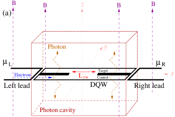
We model a two dimensional symmetric double quantum wire in a perpendicular magnetic field. The double waveguide system is placed in a photon cavity as is schematically shown in Fig. 1(a). The waveguide system is connected to two external leads with different chemical potentials where refers to the left (L) or the right (R) lead, respectively. The DQW system consists of a control- and a target-waveguide with the same width providing a symmetric double waveguide system. A window is placed between the waveguides with length (red arrow) to facilitate inter-waveguide transport. The DQW and the leads are exposed to an external magnetic field in the -direction. The total system is designed such that the electrons in the left lead are only injected into the control-waveguide (blue dashed arrow).
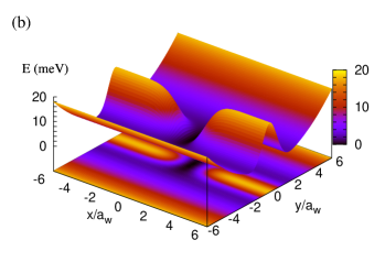
Figure 1(b) shows the DQW potential whose dimensions are characterized by the effective magnetic length . The DQW system has a hard-wall confinement in -direction at , where is the length of the waveguide system and parabolic confinement in the -direction with, , where is the characteristic energy. The DQW potential is described as
| (1) |
The first term of Eq. (1) represents a potential barrier between the quantum waveguide with meV and nm-1. The second term defines the potential of the CW with meV, and nm-1 implying a barrier width nm for the first subband. The CW length can be estimated as and which influences the electron transport between the waveguides.
II.1 DQW coupled to Cavity
Now, we demonstrate how the DQW system is coupled to the photon cavity. The Hamiltonian of the system can be described by a Many-Body (MB) Hamiltonian that describes the DQW and the photon cavity. The MB Hamiltonian consists of the electronic DQW including electron-electron interaction, the photon cavity, and the interaction between the DQW and the photon cavity. The Hamiltonian of the total system can be written as
| (2) |
The first term of Eq. (II.1) describes the DQW system without the electron-electron interaction, where is a single-electron SE state, is the effective mass of an electron, is the electron charge and and are the electron creation and annihilation operators, respectively. In addition, , where is the momentum operator, is the vector potential for the static magnetic field which can be defined as = (), and is the photon vector potential that can be introduced as
| (3) |
herein, is the amplitude of the photon field, and is the unit vector that determines the direction of the photon polarization either parallel () in a TE011 mode or perpendicular () in a TE101 mode to the transport direction. In the second term of Eq. (II.1), the Coulomb interacting electron Hamiltonian is shown with the Coulomb matrix elements in the SE state basis Abdullah et al. (2010). The third term of Eq. (II.1) denotes the free photon field, where is the quantized photon energy, and is the operator of photon creation (annihilation), respectively. In Eq. (II.1), the para-magnetic (-term), and the dia-magnetic (-term) of the electron-photon interaction are presented in which is the electron-photon coupling, and are the dimensionless electron-photon coupling tensor elements Gudmundsson et al. (2012), and is the photon number operator.
In our calculations, we include both the para- and the dia-magnetic interaction terms which lead to more complex photon-electron interaction processes than are present in the resonant two-level Jaynes-Cummings model, where only the paramagnetic term is taken into account Jaynes and Cummings (1963). In addition, we use exact diagonalization (configuration interaction) including many levels to treat the electron-electron Coulomb interaction and the electron-photon interaction Yannouleas and Landman (2007); Jonasson et al. (2012); Gudmundsson et al. (2013) without resorting to the rotating wave approximation Sornborger et al. (2004); Wu and Yang (2007).
II.2 Transport Formalism
Our model for the calculation of time dependent properties of transport through an open system requires a coupling to electron reservoirs. Here, we show how the central system is connected to the leads via coupling regions. Later in this section, a time-dependent formalism will be presented to investigate the electron transport in the system.
The total Hamiltonian of the system describing the waveguide system, the leads, and the coupling between the DQW and the leads can be written as
| (4) | ||||
where indicates the Hamiltonian of the DQW system coupled to the photon cavity shown in Eq. (II.1). The second term of the Hamiltonian describes the lead with being the dummy index representing the momentum of the standing electron waves in the semi-infinite leads and their subband number Abdullah et al. (2010), being the single-electron energy spectrum in the lead , and () being the electron creation (annihilation) operators, respectively. The last term of the Hamiltonian demonstrates the time-dependent coupling between the DQW and the leads describing a transfer of an electron between a single-electron state of the central system and a single-electron energy state of the leads through a coupling tensor
| (5) |
with () being a single-electron wave functions of the DQW system (leads). In addition, is a time-dependent function defining the onset of the coupling, and
| (6) | |||||
is a nonlocal coupling where is the coupling strength, and are the coupling parameters that control the range of the coupling in the - and -direction, respectively, and adjust the energy overlap of lead and DQW states and wavefunctions in the contact region Gudmundsson et al. (2009), and is a skewing parameter that shifts the weight of the coupling from the left lead to the control-waveguide.
We use a non-Markovian QME formalism to calculate the electron transport from the left lead to the right lead through the DQW system Breuer and Petruccione (2002). The QME approach describing the time-dependent electron transport can be obtained from quantum Liouville-von Neumann equation Esposito et al. (2009)
| (7) |
where is the density operator of the total system. The total density operator before the coupling between the waveguide system and the leads can be written as = , where and are the density operators of the isolated left and right leads, respectively Abdullah et al. (2013).
Our aim in this work is to seek the dynamics of the electron and the inter-waveguide switching processes in the system. To calculate the electron motion in the DQW system under the influence of the leads, we take the trace over the Fock space with respect to the lead variables to build a reduced density operator of the waveguide system , which leads to the Nakajima-Zwanzig equation of time-evolution in an open system Haake (p 98)
| (8) |
where is the Liouvillian with respect to the time-independent Hamiltonian of the DQW system and is the integral kernel representing the dissipative time-dependent coupling to the leads Haake (p 98); Abdullah et al. (2010). For the regime of weak coupling by sequential tunneling to the leads treated in our model we derive the dissipative kernel of Eq. 8 by keeping terms up to second order in the time dependent coupling Moldovean et al. (2009); Gudmundsson et al. (2012).
The reduced density operator allows us to calculate the left and the right charge currents into or out of the DQW Abdullah et al. (2013). Therefore, the net charge current can be introduced as
| (9) |
where denotes the partial current from the left lead into the control-waveguide and describes to the partial current into the right lead from both waveguides Abdullah et al. (2013).
To explore the properties of the charge switching between the waveguides, the expectation value of the charge current density operator in the central system is calculated. The charge current density can be defined as
| (10) |
where the charge current density operator is
| (11) |
In the following, we shall investigate numerically the influence of the cavity photon on the coherent electron transport through the DQW system in the case of - or -polarization of the photon field.
III Results and Discussion
In this section, we will discuss our numerical results that demonstrate photon-switched coherent electron transport in a double quantum waveguide. To provide coherent electron transport in the system, we consider the double waveguide system to be made of a GaAs semiconductor with length nm. It is known that the phase coherence length of a GaAs semiconductor can be nm at low temperature K Datta . Thus the coherence length is much larger than the length of the waveguide system which is an essential requirement to construct a qubit in quantum information technology.
We have fixed the following physical parameters in the calculations, the temperature of the leads is K, the chemical potentials of the leads are consider to be meV and meV, the confinement energy of the leads and the DQW system in the -direction is meV and meV, respectively, the skewing parameter is , and the electron-photon coupling strength is meV.
III.1 The system without/with photon cavity
In order to understand the influence of the photons on the transport we first explore the electron transport characteristics in the system without and with the photon cavity. Initially, the photon energy and the electron-photon coupling strength are assumed to be constant at meV and meV, respectively.
In a previous work Abdullah et al. (2014a), we demonstrated the effects of the electron-electron interaction and an external magnetic field on the electron switching process between the waveguides. In this work, we will show how photons in a cavity can be used to switch the electron motion between the waveguides.
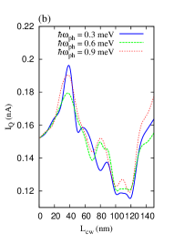
Figure 2 shows the net charge current versus the CW length without (w/o) a photon cavity (ph) (blue solid), and with (w) a photon cavity in -polarized (-p) (green dashed) and -polarized (-p) (red dotted) photon field.
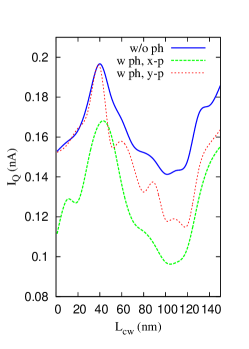
The oscillation in the net charge current depends on the transport properties of electrons between the control- and the target-waveguide. The electrons can be subjected to inter-waveguide forward or backward scattering, consequently a current peak at and a current dip at nm are formed. The net charge current decreases in the presence of cavity photon for the - and -polarized field where the cavity contains one photon initially.
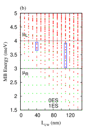
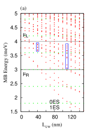
To explain the current oscillation and the suppression in the net charge current in the presence of photon cavity, we refer to the energy spectrum of the DQW system. Figure 3 shows energy spectra for the DQW system as a function of the CW length for the case of the no photon cavity (a), and for the system in the photon cavity (b). When the CW length is increased, we observe following effects in the energy spectra: the energy of the states with an electron component decreases monotonically, and generally the degeneration of energy levels reduces. We observe an energy level crossover at nm, and increased splitting of levels at nm. The weak tunneling through the central barrier between the waveguides leads to almost degenerate symmetric and antisymmetric one-electron states, but the opening of the coupling window increases the “interaction” between these states leading to a reduced degeneracy.
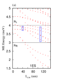
In Fig. 3(a), the low end of the spectrum with only one-electron states (1ES) (red dots) is shown for the waveguide system without the photon cavity. At nm (left blue rectangle) higher excited states enter the active bias window resulting in a level crossover with lower excited states Zibold et al. (2007); Gong et al. (2007). The energy crossover reflects a ’resonance’ energy levels between the waveguides leading to inter-waveguide transport. The contribution of the higher excited states to the electron transport increases the net charge current forming a current peak as is shown in Fig. 2 (blue line). In the current peak, the charge is transferred from the input to the output of the control-waveguide with a slight inter-waveguide forward scattering (not shown) Abdullah et al. (2014a). For the regime of increased level splitting at nm (right blue rectangle) the state of the second subband with lowest energy is the highest state in the blue rectangle enters the bias window. Even though the energy splitting indicates an ’off-resonance’ between the waveguides, the mixing of a state from the second subband with the first subband in the electron transport leads to a stronger coupling between the waveguides. Here, the charge from the control-waveguide partially switches to the target-waveguide due to inter-waveguide backward and forward scattering and is partially transferred to the output of the control-waveguide (not shown) Abdullah et al. (2014a). The inter-waveguide backward scattering decreases the net charge current forming a current dip as is shown in Fig. 2 (blue line). We should note that the two-electron states (2ES) of the energy spectrum are not active in the presence of the Coulomb interaction because the electron-electron interaction raises the 2ES well above the bias window, consequently the 2ES are effectively blocked Abdullah et al. (2014a).
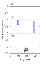
Figure 3(b) presents the MB energy spectrum including zero-electron states (0ES) (green dots) and 1ES (red dots) in the presence of a cavity including one photon initially with the photon energy meV and -polarization. The one-electron states of the energy spectrum decrease monotonically with increasing CW length while the zero-electron states (0ES) remain unchanged. We can clearly see that photon replicas for electron state appear with different photon content. The energy difference between two photon replicas is close to multiples of the photon energy in case of weak electron-photon coupling Abdullah et al. (2014b). The photon replicas of the energy levels at nm (left blue rectangle) and nm (right blue rectangle) become active in the presence of a photon cavity. To a lesser extent photon replicas of states originally below the bias region that end up in the active bias window also contribute. Therefore, more states participate in the electron transport. In addition, the shape of the active states (and the photon replicas) is influenced by the photon field. The photon field stretches or polarizes the wavefunctions.
The photon replicas have a very important and influential role in the electron-switching process in the waveguide system. At nm, the photon replicas of the ground and the first-excited states containing two photons enter the energy crossover region. The replicas containing two photons have a weaker contribution than the replicas containing one photon in the electron transport because the cavity initially contains only one photon. At nm (right blue rectangle), a photon replica of the lowest state of the second subband containing one photon participates in the electron transport. The photon replica is a localized state in the CW region leading to a suppression in the net charge current for both - (green dashed) and -polarized (red dotted) photon field at the dip as is shown in Fig. 2. However, the photon replicas of the ground state and the first excited state containing three and four photons are found among the split energy levels. But they do not influence the electron transport in any significant way.
We should mention that the energy spectrum for the -polarized photon field is very similar to the spectrum shown in Fig. 3(b) with a slightly different photon content in the MB energy states.
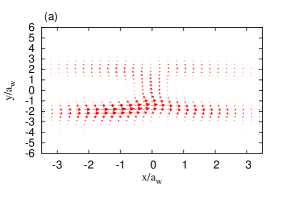
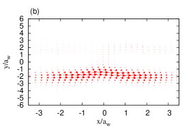
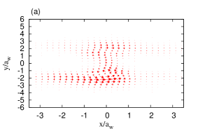
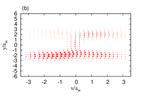
Figure 4 shows charge current density for the current peak in the -polarized (a), and the -polarized (b) photon field shown in Fig. 2 where the photon energy is meV and the electron-photon coupling is meV. In Fig. 4(a), the charge is partially transported through the control-waveguide and partially is subject to inter-waveguide backward scattering, while in the absence of the photon cavity the charge from the input of control-waveguide moves to the output of the control- and target-waveguide. The inter-waveguide backward scattering is partially caused by the charge polarization in the -direction induced by the photon field, and a weak participation of photon replica states containing two photons in the electron transport. As a result, the net charge current decreases in the dip. In Fig. 4(b) the charge remains completely within the control-waveguide because the photon energy is much smaller than the electron confinement energy in the waveguide system in the -direction. The confinement and the photon energy are meV and meV, respectively. In this case, the charge from the control-waveguide does not tunnel into the target-waveguide. The dynamic evolution of the charge in the control-waveguide implements a controlled NOT function, which is so called CNOT-operation quantum logic gate leading to enhancement in the net charge current.
III.2 Variation of the frequency and the initial number of photons
In this section, we demonstrate how the photon frequency influences the electron transport through the DQW system in the - and -polarized photon cavity. In addition, we show the effects of the number of photons initially in the cavity on electron switching processes between the waveguides. The electron-photon coupling strength is assumed to be constant at meV.
Figure 5 displays the net charge current for the -polarized (a) and -polarized (b) photon field with initially one photon in the cavity for different photon energies meV (blue solid), meV (dashed green) and meV (dotted red).
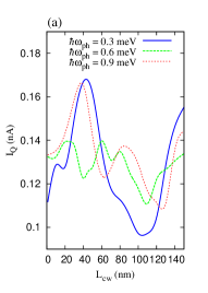
In the previous section we discussed the electron transport in the system when the photon energy is meV for both - and -polarized photon field. Now, we explore the results when the photon energy is either meV or meV.
We begin by analyzing the net charge current in the -polarized photon field shown in 5(a). In the case of a photon energy meV (dashed green), the net charge current is strongly reduced for the crossover energy at nm to a current dip instead of the current peak seen for meV, while for the region of split levels at nm the net charge current in the dip is enhanced. If we further increase the photon energy to meV (red dotted), a current peak is again seen at nm and a slightly shifted current dip at nm.
To explore the characteristics of the net charge current in the -polarized photon field, we provide Fig. 6 which shows the MB energy spectrum including zero-electron states (0ES) (green dots) and 1ES (red dots) with the photon energy meV (a) and meV (b). In Fig. 6(a) the MB energy spectrum is shown for the photon energy meV. Each MB state has photon replica with a different photon content in the presence of the photon cavity. We notice that the MB ground state is replicated into the CW with one photon and energetically enters the region of levels crossover at nm (left blue rectangle). The effect of this localized photon replicated state here on the electron transport is a suppression of the net charge current leading to a current dip. But at nm (right blue rectangle), the photon replica of the first excited state containing one photon contributes to the electron transport leading to an increasing net charge current at the dip shown in Fig. 5 (green dashed). In Fig. 6(b) the MB energy spectrum is displayed for the photon energy meV. The photon replica of neither the ground state nor the first excited states enter the active bias window (left blue rectangle). The result is that the net charge current is almost unaltered. However, at nm (right blue rectangle) the photon replica of the first excited state is found among the active split energy levels. This photon replica containing one photon enhances the net charge current in the dip.
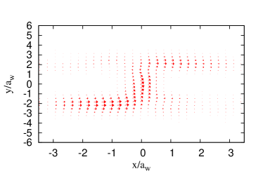
To clarify further the dynamic motion of the charge and explain the current oscillations, we present Fig. 7 which shows the charge current density at the current peak shown in Fig. 5 in the case of the photon energy meV (a), and meV (b).
In Fig. 7(a) the charge current density is seen for the current dip at nm when the photon energy is meV. The charge is localized in the CW region which suppresses the net charge current and leads to a current dip. The localized charge can be identified as a contribution of the photon replica of the MB ground state containing one photon.
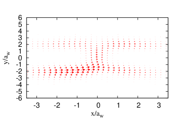
In Fig. 7(b) the charge current density for the current peak at nm is presented for photon energy meV. The charge from the input control-waveguide is equally split between the output of the control- and the target-waveguide. The photon replica of neither the ground state nor the first excited state contribute to the electron transport. But the charge density of the active states occupies both the control- and target waveguide. Therefore, the net charge current remains almost unchanged. The splitting of the charge indicates a -operation quantum logic gate action.
We have seen that the charge current density for the current dip at nm in the case of photon energy meV and meV is delocalized (not shown) while a localized charge is observed for meV. The delocalization of charge is due to participation of a photon replica of the first excited MB state. Consequently, the net charge current is enhanced.
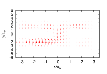
We have noticed that the electron-switching process can be achieved by tuning the photon number initially in the cavity. Let us consider two photons initially in the cavity with energy meV and photon-electron coupling strength meV. Figure 8 shows the charge current density at the CW length nm in the presence two photons in the cavity. Comparing to the charge current density in the case of one photon in the cavity with photon energy meV shown in Fig. 7(a), the charge motion in the DQW system is drastically changed. The electron charge switches totally from the input control- to the output target-waveguide. The dynamic evolution occurring in the DQW system implements a quantum logic gate operation. In this case, a Not-operation is realized by transferring the charge from the control- to the target-waveguide. The electron switching process is due to contribution of a photon replica of the both MB ground state and first-excited state containing two photons to the transport.
Let’s now look at the influences of photon frequency in the -polarized photon field on the electron-switching process. The net charge current in the presence of -polarized photon field and initially one photon in the cavity displayed in Fig. 5(b) indicates that the influences of photon frequency on the electron transport is very weak compared to the -polarized photon field for the same selected photon energies meV (blue solid), meV (green dashed) and meV (red dotted). This is due to the anisotropy of the geometry of the DQW system. The total charge-switching from the control- to the target-waveguide can not be achieved for the same selected photon energy as in the case of a -polarized photon field. For example, Fig. 9 shows the charge current density in the current peak at nm demonstrated in Fig. 5(b)(red dotted), where the cavity initially contains one photon and the photon energy is meV.
Comparing to the charge current density shown in Fig. 4(b) when the photon energy is meV, inter-waveguide transport is enhanced because the photon energy here is meV, which is close to the electron confinement energy in the waveguide system in the -direction. An electron in the control-waveguide may obtain energy from the photon to partially occupy a state in the second subband of the two parallel waveguides and thus being transferred to the target-waveguide.
In order to facilitate total electron-switching between the waveguides in the -polarization, we need to increase either the photon energy to be equal to or greater than the confinement energy of the electrons in the waveguide system in the -direction or the photon number initially present in the cavity. We now consider the photon energy to be meV, which is smaller than the electron confinement energy, ( meV) and consider two photons () initially in the cavity. An electron in the control-waveguide can absorb two photons with total energy meV and then being transferred to the target-waveguide. In this case, the charge from the input control-waveguide totally switches to the target-waveguide as is shown in Fig. 10. As a result a NOT-operation quantum logic gate action is obtained.
Our results for the two different photon polarizations have revealed that a variety of quantum logic gate actions can be observed in the waveguide system with the switching being strongly influenced by the photon energy and the photon number initially in the cavity.
IV Conclusions and Remarks
We have presented the results of a detailed investigation of how to implementing a quantum logic gate action in a semiconductor qubit by using a new and different technique, a cavity-photon-switching. In the cavity-photon-switching method, a quantized photon cavity can be used to realize a different quantum logic gate actions by varying the photon number, the photon energy, or the photon polarization.
To built a semiconductor qubit, we have considered two parallel symmetric quantum waveguides, the control- and the target-waveguide. A window is placed between them to facilitate interference and inter-waveguide electron transport. The waveguide system is connected to two leads with asymmetric coupling in which the control-waveguide is coupled to the leads from both ends while the target-waveguide is only coupled to the right lead. The DQW system is embedded in a quantized photon cavity with a photon field polarized either parallel or perpendicular to the direction of electron motion in the system in which the electron-photon interactions is described by exact numerical diagonalization. We use a non-Markovian master master equation to investigate the transient electron motion in the system.
In the absence of a photon cavity, the electron-switching process depends on the ME states active in the electron transport and their characteristics. By tuning the CW length, the energy spectrum of the DQW system monotonically decreases and new states enter and leave the bias window. Therefore, oscillation in the net charge current occur and indicating inter-waveguide forward or backward scattering into the target waveguide.
In the presence of the photon cavity, photon replicas for each MB energy state appear. The character of the active photon replicas in the electron transport depend on the photon energy, the photon number, and the photon polarization in the cavity In the case of an -polarized photon field, photon replicas contribute to the electron transport processes leading to the following scenarios: First, at high photon energy and one photon initially in the cavity a -operation quantum logic gate is found which is due to lifting the photon replica of the ground state out of the active energy states in the electron transport. Second, the charge from input the control-waveguide switches to the output of the target-waveguide in the presence of two photons in the cavity. In this case, an electron in the control-waveguide may interact with two photons and transfer to the target-waveguide. Therefore, a Not-operation quantum logic gate is implemented. For the -polarized photon field, the electron-switching processes only occur if the photon energy is equal to or greater than the electron confinement energy in the DQW system in the -direction.
We have demonstrated that the transport properties of a system with nontrivial geometry can be strongly influenced by choosing the type of electron states replicated into the active transport bias window. This control can both be excised with the photon energy and the number of photons in the cavity at the onset of an operation. It should also be stressed that our study of the time-evolution of the switching and charging processes shows that it is not necessary to await the steady state in order to complete an operation.
Acknowledgements.
This work was financially supported by the Icelandic Research and Instruments Funds, the Research Fund of the University of Iceland, the Nordic High Performance Computing facility in Iceland, and the Ministry of Science and Technology, Taiwan through Contract No. MOST 103-2112-M-239-001-MY3.References
- van Weperen et al. (2011) I. van Weperen, B. D. Armstrong, E. A. Laird, J. Medford, C. M. Marcus, M. P. Hanson, and A. C. Gossard, Phys. Rev. Lett. 107, 030506 (2011).
- Gilbert et al. (2002) M. J. Gilbert, R. Akis, and D. K. Ferry, Appl. Phys. Lett. 81, 4284 (2002).
- Ionicioiu et al. (2001) R. Ionicioiu, G. Amaratunga, and F. Udrea, Int. J. of Mod. Phys. B 15, 125 (2001).
- Bertoni et al. (2000) A. Bertoni, P. Bordone, R. Brunetti, C. Jacoboni, and S. Reggiani, Phys. Rev. Lett. 84, 5912 (2000).
- Ferry et al. (2001) D. K. Ferry, R. Akis, and J. Harris, Spperlattice and Microstructure 20 (2001).
- Marchi et al. (2003) A. Marchi, A. Bertoni, S. Reggiani, and M. Rudan, IEEE Transaction on nanotechnology 3, 129 (2003).
- Snyder and Reichl (2004) M. G. Snyder and L. E. Reichl, Phys. Rev. A 70, 052330 (2004).
- Harris et al. (2001) J. Harris, R. Akis, and D. K. Ferry, Appl. Phys. Lett. 79, 2214 (2001).
- Ramamoorthy et al. (2006) A. Ramamoorthy, R. Akis, and J. P. Bird, IEEE Transaction on nanotechnology 5, 712 (2006).
- Pingue et al. (2005) P. Pingue, V. Piazza, and B. F., Appl. Phys. Lett. 86, 052102 (2005).
- Bordone et al. (2004) P. Bordone, A. Bertoni, M. Rosini, and C. Jacoboni, Semicond.Sci.Technol. 19, 412 (2004).
- Gudmundsson et al. (2009) V. Gudmundsson, C. Gainar, C.-S. Tang, V. Moldoveanu, and A. Manolecu, New J. Phys. 11, 113007 (2009).
- Abdullah et al. (2010) N. R. Abdullah, C.-S. Tang, and V. Gudmundsson, Phys. Rev. B 82, 195325 (2010).
- Gudmundsson et al. (2012) V. Gudmundsson, O. Jonasson, C.-S. Tang, H.-S. Goan, and A. Manolescu, Phys. Rev. B 85, 075306 (2012).
- Jaynes and Cummings (1963) E. T. Jaynes and F. W. Cummings, Proceedings of the IEEE 51, 89 (1963).
- Yannouleas and Landman (2007) C. Yannouleas and U. Landman, Rep. Prog. Phys 70, 2067 (2007).
- Jonasson et al. (2012) O. Jonasson, C.-S. Tang, H.-S. Goan, A. Manolescu, and V. Gudmundsson, New journal of physics 14, 013036 (2012).
- Gudmundsson et al. (2013) V. Gudmundsson, O. Jonasson, T. Arnold, C.-S. Tang, H.-S. Goan, and A. Manolescu, Fortschr. Phys. 61, 305 (2013).
- Sornborger et al. (2004) A. T. Sornborger, A. N. Cleland, and M. R. Geller, Phys. Rev. A 70, 052315 (2004).
- Wu and Yang (2007) Y. Wu and X. Yang, Phys. Rev. Lett. 98, 013601 (2007).
- Breuer and Petruccione (2002) H.-P. Breuer and F. Petruccione, The Theory of Open Quantum Systems (Oxford University Press, Oxford, 2002).
- Esposito et al. (2009) M. Esposito, U. Harbola, and S. Mukamel, Rev. Mod. Phys. 81, 1665 (2009).
- Abdullah et al. (2013) N. R. Abdullah, C. S. Tang, A. Manolescu, and V. Gudmundsson, Journal of Physics:Condensed Matter 25, 465302 (2013).
- Haake (p 98) F. Haake, Quantum Statistics in Optics and Solid-state Physics, edited by G. Hohler and E.A. Niekisch, Springer Tracts in Modern Physics Vol. 66 (Springer, Berlin, Heidelberg, New York, 1973, p. 98.).
- Moldovean et al. (2009) V. Moldovean, A. Manolescu, and V. Gudmundsson, New journal of physics 11, 073019 (2009).
- (26) S. Datta, Electronic Transport in Mesoscopic system (Cambridge University Press, Cambridge, 1995) .
- Abdullah et al. (2014a) N. R. Abdullah, C. S. Tang, A. Manolescu, and V. Gudmundsson, arXiv:1408.1007 (2014a).
- Zibold et al. (2007) T. Zibold, P. Vogl, and A. Bertoni, Phys. Rev. B 76, 195301 (2007).
- Gong et al. (2007) J. Gong, F.-H. Yang, and S.-L. Feng, Chin. Phys. Lett. 24, 2383 (2007).
- Abdullah et al. (2014b) N. R. Abdullah, C. S. Tang, A. Manolescu, and V. Gudmundsson, Physica E 64, 254 (2014b).