20 Gordon Street, WC1H 0AJ, London, United Kingdom
2. Faculty of Information Technology, Brno University of Technology
Bozetechova 2, 612 66 Brno, Czech Republic
11email: d.groen@ucl.ac.uk, p.v.coveney@ucl.ac.uk
Weighted decomposition in high-performance lattice-Boltzmann simulations: are some lattice sites more equal than others?
Abstract
Obtaining a good load balance is a significant challenge in scaling up lattice-Boltzmann simulations of realistic sparse problems to the exascale. Here we analyze the effect of weighted decomposition on the performance of the HemeLB lattice-Boltzmann simulation environment, when applied to sparse domains. Prior to domain decomposition, we assign wall and in/outlet sites with increased weights which reflect their increased computational cost. We combine our weighted decomposition with a second optimization, which is to sort the lattice sites according to a space filling curve. We tested these strategies on a sparse bifurcation and very sparse aneurysm geometry, and find that using weights reduces calculation load imbalance by up to 85%, although the overall communication overhead is higher than some of our runs.
Keywords:
high performance computing; lattice-Boltzmann; domain decomposition1 Introduction
The lattice-Boltzmann (LB) method is widely applied to model fluid flow, and relies on a stream-collision scheme applied between neighbouring points on a lattice. These local interactions allow LB implementations to be efficiently parallelized, and indeed numerous high performance LB codes exist today [10, 14].
Today’s parallel LB implementations are able to efficiently resolve large non-sparse bulk flow systems (e.g., cuboids of fluid cells) using Petaflop supercomputers [10, 12]. Efficiently modelling sparse systems on large core counts is still an unsolved problem, primarily because it is difficult to obtain a good load balance in calculation volume, neighbour count and communication volume for sparse geometries on large core counts [13]. Additionally, the presence of wall sites, inlets and outlets create a heterogeneity in the computational cost of different lattice sites. Here we test two techniques for their potential to improve the load balance in simulations using sparse geometries, and their performance in general.
We perform this analysis building forth on existing advances. Indeed, several LB codes already provide special decomposition techniques to more efficiently model flow in sparse geometries. For example, Palabos [1], MUSUBI [14] and WaLBerla [10] apply a block-wise decomposition strategy, while codes such as HemeLB [13] and MUPHY [19] rely on third-party partitioning libraries such as ParMETIS and PT_Scotch.
Here we implement and test a weighted decomposition technique to try and improve the parallel simulation performance of the HemeLB simulation environment for sparse geometries [16], by adding weights corresponding to the computational cost of lattice sites which do not represent bulk fluid sites. In addition, we examine the effect of also pre-ordering the lattice via a space-filling curve when applying this method.
Several other groups have investigated the use of weighted decomposition in other areas, for example in environmental fluid mechanics [5]. In addition, Catalyurek et al. [9] investigate adaptive repartitioning with Zoltan using weighted graphs. Specifically, Axner et al. [4] applied a weighting technique to a lattice-Boltzmann solver for sparse geometries. Whereas we apply weights to vertices, they applied heavier weights to edges near in- and outlets, to ensure that these regions would not be distributed across several processes.
2 HemeLB
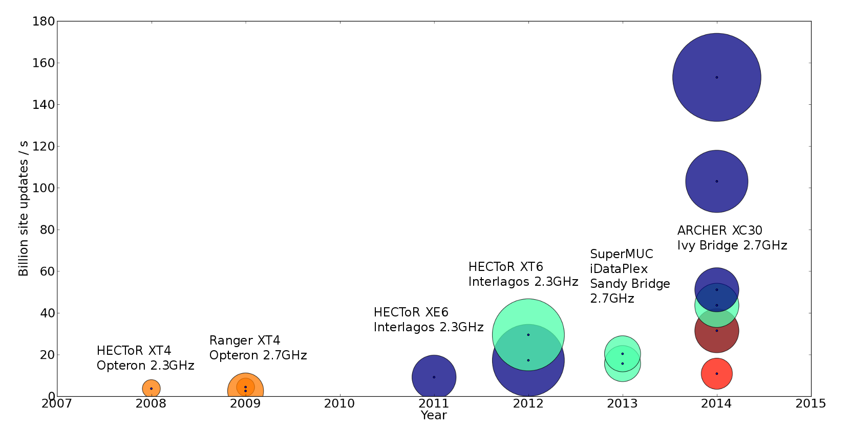
HemeLB is a high performance parallel lattice-Boltzmann code for large scale fluid flow in complex geometries. It is mainly written in C++. HemeLB supports a range of boundary conditions and collision operators [18] and features a streaming visualization and steering client [17, 13]. In addition, we have equipped HemeLB with a coupling interface, allowing it to be used as part of a multiscale simulation [11]. HemeLB uses the coalesced communication design pattern to manage its communications [8], and relies on non-blocking point-to-point MPI send and receive calls to perform data movements during the simulation. We present the improvement in performance of HemeLB over time in Fig. 1. We obtained the performance data for this figure from a variety of sources (e.g., [16, 17, 13]). Overall, the peak performance of HemeLB has improved by more than a factor 25 between 2007 and 2014, although we do now distinguish some difference in peak performance between simulations with sparse geometries (e.g., aneurysm models) and those with non-sparse geometries (e.g., cylinders). Most recently, we obtained a performance of 153 MSUPS using 49,152 cores on the ARCHER supercomputer [2]. The geometry used in these runs was a cylinder containing 230 million lattice sites.
HemeLB originally performs decomposition in two stages, making use of the ParMETIS graph partitioning library [3] version 4.0.2. In the first stage it loads the lattice arranged as blocks of 8 by 8 by 8 lattice sites. These blocks are distributed across the processes, favoring adjacent blocks when a process receives multiple blocks [16]. After this initial decomposition, HemeLB then uses the ParMETIS_V3_PartKWay() function to optimize the decomposition, abandoning the original block-level structure [13]. This function relies on a K-way partitioning technique, which first shrinks the geometry to a minimally decomposable size, then performs the decomposition, and then refines the geometry back to its original size. One of the ways we can assess the quality of the decomposition is by examining the edge cut, which is equal to the number of lattice neighbour links that cross process boundaries.
3 Description of the optimizations
We have implemented and tested two optimizations in the decomposition.
3.1 Weighting
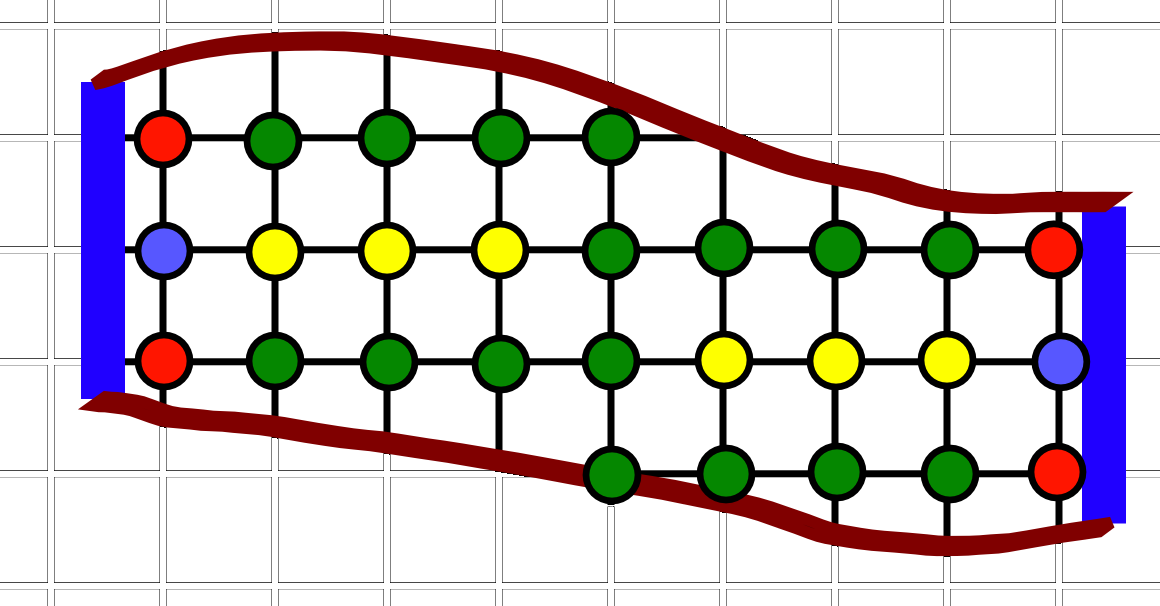
Within sparse geometries, lattice-Boltzmann codes generally adopt a range of lattice site types to encapsulate all the functionalities required to treat flow in bulk, near walls and near in- and outlets. We provide a simple example of a geometry containing these lattice site types in Fig. 2. By default, all types of lattice sites are weighted equally in HemeLB, which means that graph partitioners such as ParMETIS treat all site types with equal importance when creating a domain decomposition. However, we find that both sites adjacent to walls and sites adjacent to in- and outlets require more computational time to be updated. To optimize the load balance of the code, we therefore assign heavier weights to sites which reside adjacent to wall or in/outlet boundaries.
We are currently developing an automated tuning implementation to obtain these computational costs at run-time. However, as a first proof of concept, we have deduced approximate weighting values by running six simulations of cylinders with different aspect ratios. The shorter and wider cylinders have a relatively high ratio of in- and outlet sites, while the longer and more narrow cylinders have a relatively high ratio of wall sites. In addition, the cylinders with an aspect ratio near 1:1 have a relatively high ratio of bulk flow sites.
Based on these runs we have obtained estimated values for the computational cost for each type of lattice site, by using a least-square fitting function. We present the values of these fits, as well as rounded values we use in ParMETIS, in Table 1. ParMETIS supports using weights in graphs, provided that these weights are given as integers. As we found that using large numbers for these weights has a negative effect on the stability of ParMETIS, we chose to normalize and round the weightings such that bulk sites are given a weight of 4, and the other site types are given by values relative to that base value. Because the test runs contained only a very small number of wall + in/outlet sites, we choose to adopt the weighting for in/outlet sites also for the in/outlet sites which are adjacent to a wall boundary.
| Site type | Obtained weight | Rounded weight | |
|---|---|---|---|
| Intel | AMD | ||
| Bulk | 10.0 | 10.0 | 4 |
| Wall (BFL) | 18.708 | 20.226 | 8 |
| In/outlet | 40.037 | 37.398 | 16 |
| Wall and in/outlet | 22.700* | 34.577* | 16 |
3.2 Using a space-filling curve
A second, and more straightforward, optimization we have applied is by taking the Cartesian x,y and z coordinates of all lattice sites, and then sorting them according to Morton-ordered space-filling curve. We do this prior to partitioning the simulation domain, and in doing so, we effectively eliminate any bias introduced by the early stage decomposition scheme described in [16]. We do this by replacing the ParMETIS_V3_PartKWay() in the code function with a ParMETIS_V3_PartGeomKWay() function. This optimization is functionally independent from the weighted decomposition technique, but can lead to a better decomposition result from ParMETIS when applied.
3.3 Other optimizations we have considered
After having inserted these optimizations, we have also tried improving the partition by reducing the tolerance in ParMETIS. The amount of load imbalance permitted within ParMETIS is indicated by the tolerance value, and a lower value will increase the number of iterations ParMETIS will do to reach its final state. Decreasing the tolerance from 1.001 to 1.00001 resulted for us in an increase of the ParMETIS processing time while showing a negligible difference in the quality of partitioning. As a result, we have chosen not to investigate this optimization in this work.
4 Setup
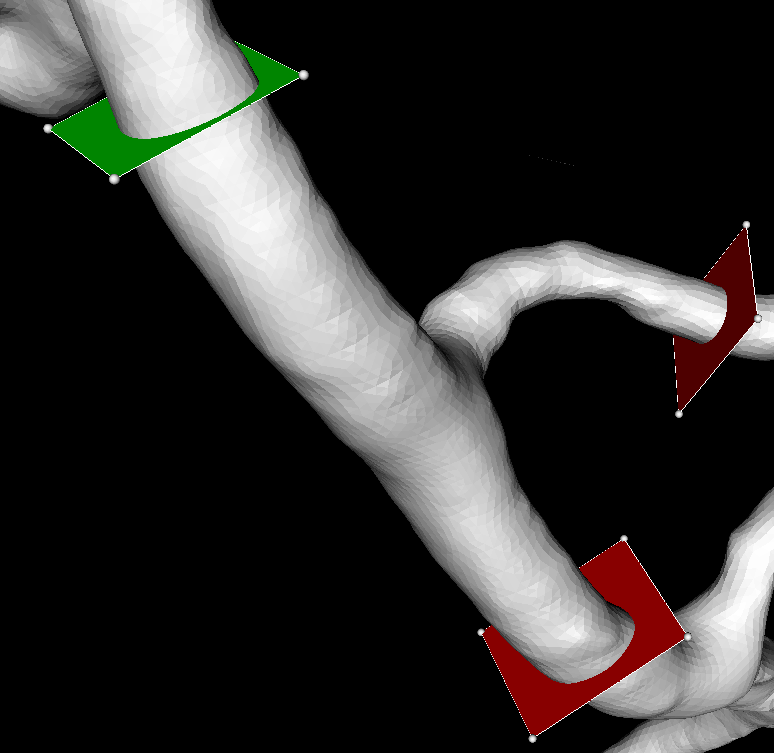
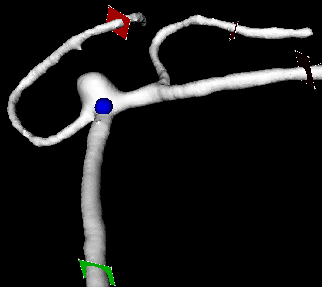
In our performance tests we used two different simulation domains. These include a smaller bifurcation geometry and a larger aneurysm geometry (see Fig. 3 for both). The bifurcation simulation domain consists of 650492 lattice sites, which occupy about 10% of the bounding box of the geometry. The aneurysm simulation domain consists of 5667778 lattice sites, which occupy about 1.5% of the bounding box of the geometry. We run our simulations using pressure in- and outlets described in Nash et al. [18], the LBGK collision operator [6], the D3Q19 advection model and Bouzidi-Firdaouss-Lallemand wall conditions [7].
For our benchmarks we use the HECToR Cray XT6 supercomputer at EPCC in Edinburgh, and compile our code using the GCC compiler version 4.3.4. We have run our simulations for 50000 time steps using 128 to 1024 cores for the bifurcation simulation domain, and 512 to 12288 cores for the aneurysm simulation domain. We repeated the run for each core count five times and averaged the results. We do this because the scheduler at HECToR does not necessarily allocate processes within a single job to adjacent nodes; and as a result the performance differs between runs. We have also performed several runs using the aneurysm simulation domain on the ARCHER Cray XC30 supercomputer at EPCC. These runs were performed with an otherwise identical configuration. ARCHER relies on an Intel Ivy Bridge architecture and has a peak performance of about 1.6 PFLOPs in total.
5 Results
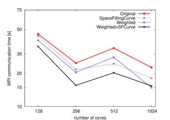
We present our measurements of the total simulation time and the maximum LB calculation time for the bifurcation simulation domain in Figure 4.
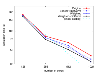
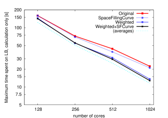
We find that both incorporating a space-filling curve and using weighted decomposition results in a reduction of the simulation time. However, the use of a space-filling curve does little to reduce the calculation load imbalance, whereas enabling weighted decomposition results in a reduction of the calculation load imbalance by up to 85%. We also examined the edge-cut returned by ParMETIS during the domain decomposition stage. For each core count, the edge cut obtained in all the runs was within a margin of 4.5%, with slightly higher edge cuts for runs using a space-filling curve or weighted decomposition.
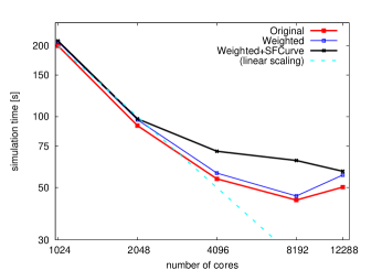
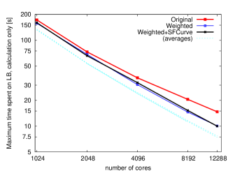
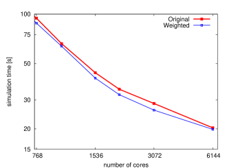
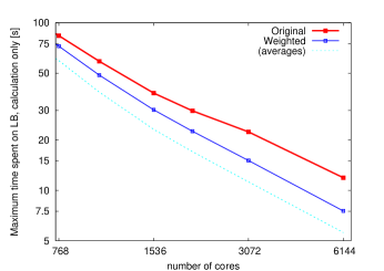
We present our measurements of the total simulation time and the maximum LB calculation time for the aneurysm simulation domain in Figure 5. Here we find that applying weighted decomposition results in an increase of runtime by 5% in most of our runs. Using the space-filling curve in addition to the weighted decomposition results in a further increase in runtime, especially for runs performed on 4096 and 8192 cores. However, the use of weighted decomposition also results in a calculation load imbalance which is up to 65% lower than that of the original simulation, while we again observe little difference here between runs that use a space-filling curve and the runs without. When we examine the edge cut obtained by ParMETIS in different runs, we find that using weighted decomposition results in a slightly lower edge cut ( 0.5%) and using a space-filling curve results in an edge cut which is up to 5.3% higher.
To provide more insight into the cause of the increase in simulation time, we present our measurements of the MPI communication overhead in these runs in Fig. 6. Here the runs which use our optimization strategies take less time to do MPI communication when applied to the bifurcation simulation domain, and more time to do MPI communications when applied to the aneurysm domain. These differences match largely with the differences we observed in the overall simulation time. Because the total time spent on MPI communications is generally larger than the calculation time for high core counts, and the differences between the runs are considerable, the communication performance is a major component of the overall simulation performance. However, the communication performance correlates only weakly with the edge cut values returned by ParMETIS and therefore the total communication volume. For example, the slightly lower edge cut for the aneurysm simulations with weighted decomposition is in contrast with the slightly higher communication overhead. This means that the communication load imbalance is likely to be a major bottleneck in the performance of our larger runs, and should be investigated more closely.
5.1 Performance Results on ARCHER
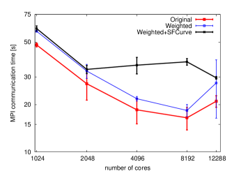
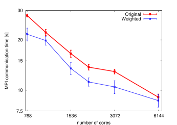
We have repeated the simulations using the aneurysm simulation domain on the ARCHER supercomputer, both with and without using weighted decomposition. We present the measured simulation and calculation times of these runs in Fig. 7, and the MPI communication time in Fig. 8. In these runs, we obtained approximately three times the performance per core compared to HECToR. When using weighted decomposition, the calculation load imbalance was reduced by up to 70%, the simulation time by approximately 2-12% and the MPI communication time by approximately 5-20%. In particular, the reduction in communication time contrasts with the measured increase in communication time, which we observed in the HECToR runs. This difference could be attributed to the superior network architecture of ARCHER, and/or the large memory per core, which may have resulted in ParMETIS reaching a domain decomposition with better communication load balance.
6 Discussion and conclusions
We presented an approach for weighted decomposition and assessed its effect on the performance of the HemeLB bloodflow simulation environment. The use of lattice weights in our decomposition scheme provides the strongest improvement in calculation load balance, and delivers an improvement in the simulation performance for the bifurcation geometry. However, the use of weighted decomposition (both with and without the space-filling curve optimization) sometimes results in a higher communication overhead of the aneurysm simulations, despite negligible changes in the communication volume. Indeed, for these blood flow simulations it appears that a low edge cut is only a minor factor in the overall communication performance for sparse problems, even though graph partitioning libraries are frequently optimized to accomplish such a minimal edge cut. This is in accordance with some earlier conclusions in the literature [15]. We intend to more thoroughly investigate the communication load imbalance of our larger runs. As part of preparing HemeLB for the exascale within the CRESTA project, we are working with experts from the Deutschen Zentrums für Lucht und Raumfahrt (DLR) to enable domain decompositions using PT-Scotch and Zoltan. The use of these alternate graph partitioning libraries may result in further performance improvements, especially if these libraries optimize not only for a calculation load balance and a low edge cut, but also take into account other communication characteristics. Furthermore, since we have observed differences in site weights between different computer architectures, we are looking into an ”auto-tuning” function that automatically calculates the weights at runtime or compilation time.
7 Acknowledgements
We thank Timm Krueger for his valuable input. This work has received funding from the CRESTA and MAPPER projects within the EC-FP7 (ICT-2011.9.13) under Grant Agreements nos. 287703 and 261507, and from EPSRC Grants EP/I017909/1 (www.2020science.net) and EP/I034602/1. This work made use of the HECToR supercomputer at EPCC in Edinburgh, funded by the Office of Science and Technology through EPSRC’s High End Computing Programme.
References
- [1] Palabos LBM Wiki - http://wiki.palabos.org/, 2011.
- [2] Cresta case study: Application soars above petascale after tools collaboration - http://www.cresta-project.eu/images/cresta_casestudy1_2014.pdf, 2014.
- [3] ParMETIS - http://glaros.dtc.umn.edu/gkhome/metis/parmetis/overview, 2014.
- [4] L. Axner, J. Bernsdorf, T. Zeiser, P. Lammers, J. Linxweiler, and A. G. Hoekstra. Performance evaluation of a parallel sparse lattice Boltzmann solver. Journal of Computational Physics, 227(10):4895 – 4911, 2008.
- [5] M. F. Barad, P. Colella, and S. G. Schladow. An adaptive cut-cell method for environmental fluid mechanics. International journal for numerical methods in fluids, 60(5):473–514, 2009.
- [6] P. L. Bhatnagar, E. P. Gross, and M. Krook. A model for collision processes in gases. i. small amplitude processes in charged and neutral one-component systems. Phys. Rev., 94:511–525, May 1954.
- [7] M. Bouzidi, M. Firdaouss, and P. Lallemand. Momentum transfer of a Boltzmann-lattice fluid with boundaries. Phys. Fluids, 13(11):3452–3459, 2001.
- [8] H. B. Carver, D. Groen, J. Hetherington, R. W. Nash, M. O. Bernabeu, and P. V. Coveney. Coalesced communication: a design pattern for complex parallel scientific software. submitted to Advances in Engineering Software, October 2012.
- [9] U. V. Catalyurek, E. G. Boman, K. D. Devine, D. Bozdag, R. Heaphy, and L. A. Riesen. Hypergraph-based dynamic load balancing for adaptive scientific computations. In Parallel and Distributed Processing Symposium, 2007. IPDPS 2007. IEEE International, pages 1–11. IEEE, 2007.
- [10] C. Godenschwager, F. Schornbaum, M. Bauer, H. Köstler, and U. Rüde. A framework for hybrid parallel flow simulations with a trillion cells in complex geometries. In Proceedings of SC13: International Conference for High Performance Computing, Networking, Storage and Analysis, SC ’13, pages 35:1–35:12, New York, NY, USA, 2013. ACM.
- [11] D. Groen, J. Borgdorff, C. Bona-Casas, J. Hetherington, R. W. Nash, S. J. Zasada, I. Saverchenko, M. Mamonski, K. Kurowski, M. O. Bernabeu, A. G. Hoekstra, and P. V. Coveney. Flexible composition and execution of high performance, high fidelity multiscale biomedical simulations. Interface Focus, 3(2), April 6, 2013.
- [12] D. Groen, O. Henrich, F. Janoschek, P. V. Coveney, and J. Harting. Lattice-boltzmann methods in fluid dynamics: Turbulence and complex colloidal fluids. In Jülich Blue Gene/P Extreme Scaling Workshop, 2011.
- [13] D. Groen, J. Hetherington, H. B. Carver, R. W. Nash, M. O. Bernabeu, and P. V. Coveney. Analyzing and modeling the performance of the HemeLB lattice-Boltzmann simulation environment. Journal of Computational Science, 4(5):412 – 422, 2013.
- [14] M. Hasert, K. Masilamani, S. Zimny, H. Klimach, J. Qi, J. Bernsdorf, and S. Roller. Complex fluid simulations with the parallel tree-based lattice boltzmannsolver musubi. Journal of Computational Science (in press), (0):–, 2013.
- [15] B. Hendrickson and T. G. Kolda. Graph partitioning models for parallel computing. Parallel computing, 26(12):1519–1534, 2000.
- [16] M. D Mazzeo and P. V. Coveney. HemeLB: A high performance parallel lattice-Boltzmann code for large scale fluid flow in complex geometries. Computer Physics Communications, 178(12):894–914, 2008.
- [17] M. D. Mazzeo, S. Manos, and P. V. Coveney. In situ ray tracing and computational steering for interactive blood flow simulation . Computer Physics Communications, 181:355–370, 2010.
- [18] R. W. Nash, H. B. Carver, M. O. Bernabeu, J. Hetherington, D. Groen, T. Krüger, and P. V. Coveney. Choice of boundary condition for lattice-Boltzmann simulation of moderate Reynolds number flow in complex domains. accepted by Physics Review E, 2014.
- [19] A. Peters, S. Melchionna, E. Kaxiras, J. Lätt, J. Sircar, M. Bernaschi, M. Bison, and S. Succi. Multiscale simulation of cardiovascular flows on the ibm bluegene/p: Full heart-circulation system at red-blood cell resolution. In Proceedings of the 2010 ACM/IEEE International Conference for High Performance Computing, Networking, Storage and Analysis, SC ’10, pages 1–10, Washington, DC, USA, 2010. IEEE Computer Society.