GENFIT – a Generic Track-Fitting Toolkit
Abstract
Genfit is an experiment-independent track-fitting toolkit that combines fitting algorithms, track representations, and measurement geometries into a modular framework. We report on a significantly improved version of Genfit, based on experience gained in the Belle II, p anda, and FOPI experiments. Improvements concern the implementation of additional track-fitting algorithms, enhanced implementations of Kalman fitters, enhanced visualization capabilities, and additional implementations of measurement types suited for various kinds of tracking detectors. The data model has been revised, allowing for efficient track merging, smoothing, residual calculation, alignment, and storage.
- AVF
- Adaptive Vertex Fitter
- AVR
- Adaptive Vertex Reconstructor
- basf2
- Belle II analysis framework
- DAF
- deterministic annealing filter
- FOPI
- A detector located at heavy ion research center, GSI
- GBL
- general broken lines
- MC
- Monte Carlo
- NDF
- number of degrees of freedom
- p anda
- Anti-Proton Anniliation at Darmstadt
- POCA
- point of closest approach
- Rave
- Reconstruction (of vertices) in Abstract, Versatile Environments
- RKTrackRep
- Runge-Kutta track representation
- TPC
- Time Projection Chamber
- TrackCand
- track candidate
- TrackRep
- track representation
- TUM
- Technische Universität München
- UML
- Unified Modeling Language
1 Introduction
Genfit provides an extensible modular open-source framework that performs track fitting and other related tasks and thus eliminates the redundancy of writing track-fitting programs for every experiment [11]. Smaller experiments, which do not have the manpower to develop their own track fitters, and new experiments, which need working tools to research and develop, are especially encouraged to use Genfit. Genfit can also be a valuable teaching aid; the 3D display excellently illustrates track fitting.
All particle physics experiments need to identify and classify processes based on detector signals. Combining these signals to recover particle trajectories is the task called tracking: Suitable collections of measurements must be combined into track candidates. Tracks must be fitted and points of common origin or exit, vertices, must be found and fitted. Track finding and track fitting are not independent from each other. Steps of different levels of track finding and refining alternate with track-fitting steps. Fitted tracks from different tracking subdetectors can be matched and combined into larger tracks; and single measurements can be appended to existing tracks, which might come from another subdetector. Provided suitable collections of measurements, all of these tasks can be performed with Genfit.
Genfit was successfully used during a test of the Belle II high-level trigger architecture and the combined Belle II vertex-detector readout architecture [2]. There it served for online track reconstruction in the data-reduction stage of the high-level trigger, as well as for offline analysis. It was also used as the track fitter supplying input to the Millipede II alignment software [3].
2 The three pillars of track fitting
Track fitting in Genfit is based on three pillars: Measurements, track representations, and fitting algorithms. Measurements serve as objects containing measured coordinates from a detector. They provide functions to construct a (virtual) detector plane and to provide measurement coordinates and covariance in that plane. The abstract base class AbsMeasurement defines the interface. Genfit comes with predefined measurement classes for various detector types, including planar detectors, drift chambers, and time projection chambers.
For planar detectors, the detector plane is given by the detector geometry, whereas for wire and spacepoint measurements, so-called virtual detector planes are constructed. Further information can be used here, allowing one to compensate for detector deformations like plane bending, wire sag, and misalignment. Drift-time corrections and cluster fits (track dependent clustering) are possible.
Track representations combine track-parameterization and track-extrapolation code. Genfit implements a track representation based on a Runge-Kutta extrapolator (RKTrackRep, see below).
Fitting algorithms use the measurements and track representations to calculate fit results, which are stored in corresponding objects in the Track object.
3 The track data structure
All per-track data is kept in the Track object (Fig. 1). It holds a sequence of TrackPoint objects, which can contain measurements, FitterInfo objects, which hold all fitter-specific information, and thin scatterers (currently only used in the GBL fitter).
A Track contains one or more track representations, representing the particle hypotheses that should be fitted. One of them must be selected as the cardinal track representation. This can be done by the user or by Genfit, which selects the track representation that best fits the measurements (i.e. has the lowest ).
The Track also contains a FitStatus object, which stores general information (number of iterations, convergence, etc.) and fit properties (, NDF, value, track length, etc.).
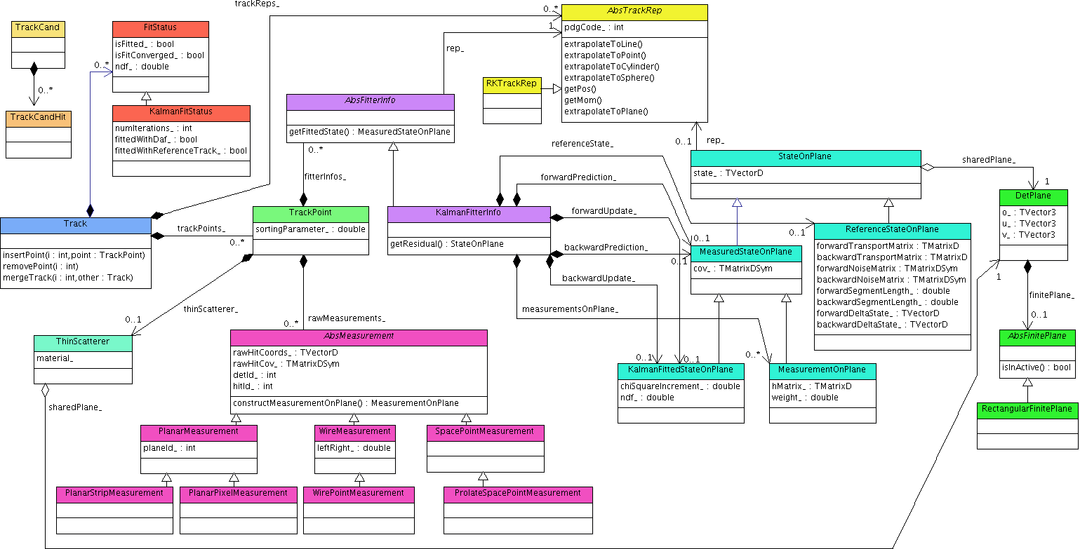
The track candidate (TrackCand) serves as a helper class, basically storing indices of raw detector hits in TrackCandHit objects, which can also be overloaded by the user to store additional information. WireTrackCandHit objects can store the left-right ambiguity. A use case is pattern recognition: algorithms can work on raw objects that are lighter weight than a Measurement or implement other features needed by the pattern recognition but not necessarily by Genfit. Genfit’s MeasurementFactory can build a Track from a TrackCand. This Track can then be processed by the various fitting algorithms.
After fitting, Track objects contain a lot of data: track representations, TrackPoint objects with measurements, FitterInfo objects, etc. Usually, not all of this information needs to be stored on disk. E.g. for physics analysis only parameters near the vertex and information on the track quality are necessary, whereas alignment needs residual information at all measurements. The user can decide which data to keep; e.g. only the fitted state of the first TrackPoint, and only for the cardinal track representation.
4 Runge-Kutta track representation
The Runge-Kutta track representation (RKTrackRep) is based on a Runge-Kutta extrapolator from Geant 3 [5]. An abstract interface class interacts with the detector geometry. Implementations using Root’s TGeoManager [4] and Geant4’s G4Navigator [10] are available. During fitting, material properties are used to calculate the following effects: energy loss and energy-loss straggling for charged particles according to the Bethe Bloch formula (code ported from Geant 3); multiple scattering (according to Ref. [7] or using the Highland formula), where the full noise matrix is calculated; and soft Bremsstrahlung energy loss and energy-loss straggling for and (code ported from Geant 3).
The step sizes used for the Runge-Kutta extrapolation should be as large as possible to save unnecessary computation, while still being small enough to keep errors reasonably small. An adaptive step-size calculation is done in the RKTrackRep, taking field inhomogeneities and curvature into account. To calculate material effects correctly, extrapolation stops at material boundaries and steps can only be so large that a maximum relative momentum loss in the material is not exceeded.
RKTrackRep provides different methods to find the point of closest approach (POCA) of the track to nonplanar measurements. These are used to construct virtual detector planes:
-
•
Extrapolate to point finds the POCA of the track to a given spacepoint. The virtual detector plane contains the spacepoint and the POCA and is perpendicular to the track.
A weight matrix can be used as a metric, defining the space in which the POCA will be calculated. By default, the inverted 3D covariance of a spacepoint measurement is used as a metric, which gives correct fitting results also for spacepoints with arbitrary covariance shapes. Again, the virtual detector plane contains the spacepoint and the POCA and is perpendicular to the track in the space defined by the metric.
- •
The intersection of the virtual detector plane and the measurement covariance gives the covariance in the plane.
5 Fitter implementation details
Four different track-fitting algorithms are currently implemented: two smoothing Kalman filters, one which linearizes the transport around the state predictions and one which linearizes around a reference track; a deterministic annealing filter (DAF); and a general broken lines (GBL) fitter.
Genfit provides the possibility to store several measurements of the same type in one TrackPoint, mainly for using the DAF to assign weights to them. Wire measurements also produce two MeasurementOnPlane objects, representing the passage of the particle on either side of the wire. These tracks can also be fitted with the Kalman fitters. Genfit provides several ways to handle multiple measurements:
-
•
The weighted average of the individual measurements is calculated. This is used by the DAF.
-
•
The measurement closest to the state prediction or reference state is selected.
-
•
If the TrackPoint has a wire measurement, the side that is closest to the prediction or reference is select; otherwise the average is selected.
For wire measurements, it turned out that selecting the side closest to the state prediction is the best option for the Kalman fitters.
As convergence criteria, a minimum and maximum number of iterations can be set, which are 2 and 4 by default. After the minimum number of iterations, Genfit checks if the value has changed less than a certain amount since the previous iteration; the default is . However, tracks with a value close to zero are often considered as converged with this criterion, even though the , albeit big, is still changing significantly, indicating that the fit is still improving. This occurs often for tracks that are given bad start parameters. To cure this issue, a nonconvergence criterion has been introduced: If the relative change in from one iteration to the next is larger than , the fit will continue. Again, this number is user-adjustable.
5.1 Kalman fitter
5.2 Kalman fitter with reference track
State predictions may stray very far from actual trajectories. Consequently, linearizing around them is not optimal; material and magnetic field lookups are also not done at the proper places. It is therefore common to linearize around reference states [8], which are calculated by extrapolating the start parameters to all TrackPoint objects. At later iterations, the smoothed states from the previous iterations are used as linearization points. However, if the change would be very small, reference states are not updated, saving computing time. It is also possible to let the fitter sort the measurements along the reference track, which can improve fitting accuracy.
In addition to the convergence criteria detailed above, the fit is regarded as converged if none of the reference states has been updated since the previous iteration.
5.3 Deterministic annealing filter
The deterministic annealing filter [9] is a powerful tool for the rejection of outlying measurements. It is a Kalman filter that uses a weighting procedure between iterations based on the measurement residuals to determine the proper weights. The user can select which of Genfit’s two Kalman-fitter implementations should be used and specify the annealing scheme.
The DAF is also perfectly suited to resolving the left-right ambiguities of wire measurements. However, a problem can occur: The weights of the MeasurementOnPlane objects must be initialized. The basic solution is to initialize both left and right measurements with a weight of 0.5. Effectively the wire positions are taken as measurements in the first iteration, and their covariance is twice the mean of the individual covariances. So all the wire positions have the same covariance, no matter how far from the actual trajectory they are. This systematically false estimate of the covariances biases the fit. Genfit implements a novel technique to initialize the weights that improves the fitting efficiency: Measurements with larger drift radii are assigned smaller weights, leading to larger covariances since the wire position is expected to be farther away from the trajectory. In contrast, measurements with smaller drift radii, which are closer to the trajectory, get larger weights.
After the annealing scheme, convergence is checked: If the absolute change of all weights is less than (user configurable), the fit is regarded as converged. Otherwise another iteration with the last temperature is done, until the fit converges or a maximum number of iterations is reached.
5.4 Generalized broken lines fitter
The generalized broken lines method of track fitting [12] was implemented especially for the purpose of alignment with Millipede II. It is mathematically equivalent to the Kalman fitter (with thin scatterers instead of continuous materials), but fits tracks in their entirety in one step, providing a natural interface to the Millipede II software. For alignment purposes, Genfit also provides a set of interfaces for alignment parameters and derivatives which can be implemented by the detector classes.
6 Vertex reconstruction with GFRave
GFRave, an interface to the vertex-fitting framework Rave111Reconstruction (of vertices) in Abstract, Versatile Environments, has been implemented. Rave [14] is a detector-independent toolkit for vertex reconstruction originally developed for the CMS experiment [6]. GFRave takes full advantage of the Genfit material model and the sophisticated algorithms of Rave, allowing for precise and fast vertex reconstruction.
7 Performance
The execution time of the GenFitter module in the Belle II software framework [13] was measured on a office PC in single-threaded operation. All code was compiled with -O3 optimization settings. Besides fitting all tracks in an event, this module builds data structures for Belle II’s data storage format, incurring an overhead of slightly less than . Single track events were generated with a particle gun, with and a momentum of in a constant magnetic field. The resulting Track objects found by MC-based (perfect) track finding contain TrackPoint objects. The Kalman fitters have been configured to do 3 to 10 iterations with default convergence criteria, while the DAF uses its default annealing scheme with 5 temperatures.
From the results shown in Tab. 1, one can see that the Kalman fitter with reference track needs fewer iterations to converge. Material lookup requires approximately per iteration for the Kalman fitter. The Kalman fitter with reference track is also faster here, since the reference states are not recalculated if they are close to the smoothed states of the previous iteration. This is also the reason why the reference Kalman can often finish after 2 iterations.
| \brFitter | w/o matFX | w/ matFX | iterations |
|---|---|---|---|
| \mrKalman | 3 | ||
| Reference Kalman | 2.13 | ||
| DAF | 6 | ||
| \br |
8 Visualisation
Genfit features a sophisticated 3D event display, which allows one to visualize fitted tracks. Detector geometry, measurements, detector planes, reference tracks, forward and backward fits (predictions and updates), smoothed tracks, and covariances of measurements and tracks can be drawn. Tracks can be refitted with different algorithms and settings, and fit results can be viewed instantly.
Fig. 2 shows the fit of a set of measurements with the Kalman fitter with reference track. For demonstration purposes, the different measurement types supported by Genfit are used (starting from the origin): planar pixel measurement, spacepoint measurement, prolate spacepoint measurement, two perpendicular planar strip measurements, double-sided planar strip measurement, wire measurement, and wire measurement with second coordinate measurement.
Acknowledgments
This research was supported by the DFG cluster of excellence “Origin and Structure of the Universe.” T.S. was supported under BMBF Contract 05H12WM8.
References
- [1] Brian D.O. Anderson and John B. Moore. Optimal Filtering. Dover Publications, 1979.
- [2] T. Bilka et al. Demonstrator of the Belle II Online Tracking and Pixel Data Reduction on the High Level Trigger System. 2014. subm. IEEE Trans. Nucl. Sc. arXiv:1406.4955.
- [3] V. Blobel. Software alignment for tracking detectors. Nucl.Instrum.Meth., A566:5–13, 2006. doi:10.1016/j.nima.2006.05.157.
- [4] Rene Brun and Fons Rademakers. Root - an object oriented data analysis framework. In AIHENP’96 Workshop, Lausane, volume 389, pages 81–86, 1996.
- [5] CERN. GEANT - Detector description and simulation tool. CERN Program Library Long Write-up, W5013, 1993.
- [6] CMS Collaboration. The CMS experiment at the CERN LHC. JINST, 0803:S08004, 2008. doi:10.1088/1748-0221/3/08/S08004.
- [7] A. Fontana, P. Genova, L. Lavezzi, and A. Rotondi. Track Following in Dense Media and Inhomogeneous Magnetic Fields. PANDA Report PV/01-07, 2007.
- [8] R. Frühwirth, M. Regler, R.K. Bock, H. Grote, and D. Notz. Data Analysis Techniques for High-Energy Physics. Cambridge University Press, 2000.
- [9] R. Frühwirth and A. Strandlie. Track Fitting with Ambiguities and Noise: A Study of Elastic Tracking and Nonlinear Filters. Computer Physics Communications, 120(2-3):197 – 214, 1999. doi:10.1016/S0010-4655(99)00231-3.
- [10] GEANT 4 Collaboration. GEANT 4 – a simulation toolkit. Nucl. Inst. Methods Phys. Res., A506:250–303, 2003.
- [11] C. Höppner, S. Neubert, B. Ketzer, and S. Paul. A Novel Generic Framework for Track Fitting in Complex Detector Systems. Nucl.Instrum.Meth., A620:518–525, 2010. arXiv:0911.1008, doi:10.1016/j.nima.2010.03.136.
- [12] C. Kleinwort. General Broken Lines as advanced track fitting method. Nucl.Instrum.Meth., A673:107–110, 2012. arXiv:1201.4320, doi:10.1016/j.nima.2012.01.024.
- [13] Andreas Moll. The software framework of the Belle II experiment. J.Phys.Conf.Ser., 331:032024, 2011. doi:10.1088/1742-6596/331/3/032024.
- [14] Wolfgang Waltenberger. RAVE: A Detector-independent Toolkit to Reconstruct Vertices. IEEE Trans. Nucl. Sci., 58:434–444, 2011. doi:10.1109/TNS.2011.2119492.