Circuit QED: Implementation of the three-qubit refined Deutsch-Jozsa quantum algorithm
Abstract
We propose a protocol to construct the 35 -controlled phase gates of a three-qubit refined Deutsch-Jozsa (DJ) algorithm, by using single-qubit gates, two-qubit controlled phase gates, and two-target-qubit controlled phase gates. Using this protocol, we discuss how to implement the three-qubit refined DJ algorithm with superconducting transmon qutrits resonantly coupled to a single cavity. Our numerical calculation shows that implementation of this quantum algorithm is feasible within the present circuit QED technique. The experimental realization of this algorithm would be an important step toward more complex quantum computation in circuit QED.
pacs:
03.67.Lx, 42.50.Dv, 85.25.CpI INTRODUCTION
As one of the most promising solid-state candidates for quantum information processing [1,2], the physical system composed of circuit cavities and superconducting qubits is of particular interest. This is because: (i) superconducting qubits and microwave resonators (a.k.a. cavities) can be fabricated using modern integrated circuit technology, and their properties can be characterized and adjusted in situ, (ii) superconducting qubits have relatively long decoherence times [3,4], and (iii) a superconducting microwave cavity or resonator plays a role of quantum bus which can mediate long-range and fast interaction between distant superconducting qubits [5-7]. Moreover, the strong coupling between the cavity field and superconducting qubits, which is difficult to implement with atoms in a microwave cavity, was earlier predicted in theory [1,8] and has been experimentally demonstrated [9,10]. Because of these features, circuit QED has been widely utilized for quantum information processing. Based on circuit QED, many theoretical proposals have been presented for realizing two-qubit gates [5,11-18] and multiple qubit gates [19-20] with superconducting qubits. Moreover, experimental demonstration of two-qubit gates [6,7,21,22] and three-qubit gates [23-25] with superconducting qubits in circuit QED has been also reported.
The interest in quantum computation is stimulated by the discovery of quantum algorithms [26,27] which can solve problems of significance much more efficiently than their classical counterparts. Among important quantum algorithms, there exist the Deutsch algorithm [28], the Deutsch-Jozsa algorithm [29], the Shor algorithm [30], the Simon algorithm [31], the quantum Fourier transform algorithm, and the Grover search algorithm [32]. As is well known, the Deutsch algorithm and the Deutsch-Jozsa algorithm were the first two that make use of the features of quantum mechanics for quantum computation. Compared with other quantum algorithms, these two algorithms are easy to be implemented and thus have been considered as the natural candidates for demonstrating power of quantum computation.
We note that with superconducting qubits coupled to a circuit cavity, a two-qubit Deutsch-Jozsa quantum algorithm and a two-qubit Grover search quantum algorithm were previously demonstrated in experiments [7]. However, after a thorough investigation, we note that how to implement a three-qubit Deutsch-Jozsa (DJ) quantum algorithm with superconducting qubits or qutrits in circuit QED has not been reported in both theoretical and experimental aspects. As is known, the experimental realization of the three-qubit DJ algorithm with a cavity-superconducting-device system is important because it would be an important step toward more complex quantum computation in circuit QED.
In this paper, we propose a protocol to construct the 35 -controlled phase gates of a three-qubit refined DJ algorithm, by using single-qubit gates, two-qubit CP gates, and two-target-qubit CP gates. It should be noted that a two-target-qubit CP gate consists of two sequential controlled gates, which have a common control qubit but a different target qubit. The protocol is quite general and can be applied to implement the three-qubit DJ algorithm in various of physical systems. Based on this protocol, we further discuss how to implement the three-qubit refined DJ algorithm with superconducting transmon qutrits resonantly coupled to a single cavity. Our numerical calculation shows that implementation of this quantum algorithm is feasible within the present circuit QED technique.
The paper is organized as follows. In Sec. II, we review the refined DJ algorithm. In Sec. III, we present a protocol to construct the 35 -controlled phase gates. In Sec. IV, we discuss how to implement this DJ algorithm with superconducting transmon qutrits coupled to a cavity via resonant interaction, and analyze the experimental feasibility. A concluding summary is given in Sec. V.
II REFINED DEUTSCH-JOZSA ALGORITHM
The DJ algorithm is aimed at distinguishing the constant function from the balanced functions on inputs. The function takes either or For the constant function, the function values are constant ( or ) for all inputs. In contrast, for the balanced function, the function values are equal to 1 for half of all the possible inputs, and for the other half. Using the DJ algorithm, whether the function is constant or balanced can be determined by only one query. However, a classical algorithm would require queries to answer the same problem, which grows exponentially with input size.
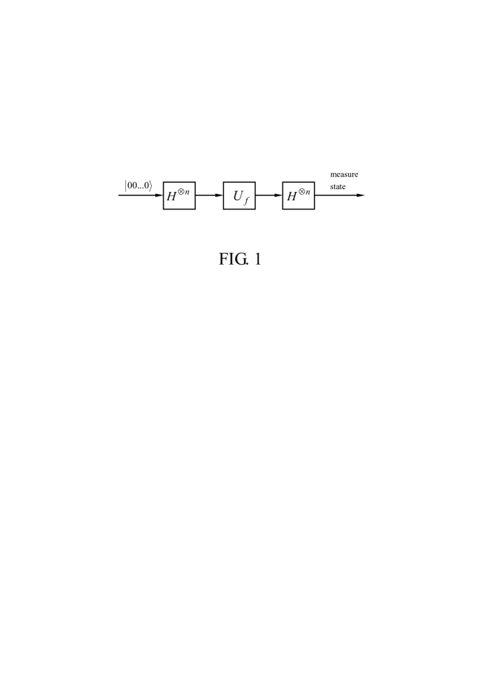
The refined DJ algorithm was proposed by Collins et al. in 2001 [33], which is illustrated in Fig. 1. This refined DJ algorithm is described below:
(i) Each input query qubit is prepared in the initial state
(ii) Perform a Hadamard transformation on each qubit, resulting in and ). As a result, the -qubit initial state changes to the state (denoted as ).
(iii) Apply the -controlled phase shift , described by
| (1) |
which leads the state to the state (denoted as ).
(iv) Perform another Hadamard transformation on each qubit. As a result, the state becomes
(v) Measure the final state of the qubits. If the qubits are measured in the state then is constant. However, if they are measured in other -qubit computational basis states, then is balanced. This is because the amplitude of the state is given by which is for a constant while for a balanced .
One can see that when compared with the original DJ algorithm [29], this refined DJ algorithm does not need an auxiliary working qubit. Hence, it requires one qubit fewer than the original DJ algorithm. Consequently, its physical implementation requires one fewer two-state system.
![[Uncaptioned image]](/html/1410.3049/assets/x2.png)
![[Uncaptioned image]](/html/1410.3049/assets/x3.png)
III PROTOCOL FOR CONSTRUCTION OF THE -CONTROLLED PHASE GATES
For a -qubit DJ algorithm, there are a total of balanced functions, among which only balanced functions are nontrivial if the symmetry is taken into account. For the three-qubit DJ algorithm, i.e., there thus exist nontrivial balanced functions (see Table I). In this section, we show how to construct the 35 -controlled phase gates, by using single-qubit gates, two-qubit CP gates, and two-target-qubit CP gates.
A single qubit gate results in the transformation while A two-qubit CP gate on qubits and considered here is described as follows
| (2) |
which implies that if and only if the control qubit (the first qubit) is in the state , a phase flip happens to the state of the target qubit (the second qubit), but nothing happens otherwise. In addition, a two-target-qubit CP gate with the control qubit and the two target qubits and is defined below
| (3) |
which shows that if and only if the control qubit (the first qubit) is in the state a phase flip happens to the state of the target qubit (the second qubit) and the state of the target qubit (the last qubit).
The construction for each of the 35 -controlled phase gates is listed in Table II. One can see from Table II that the 35 -controlled phase gates are classified into the following four types: (i) Type 1 includes seven -controlled phase gates each constructed with single-qubit gates only; (ii) Type 2 contains twelve -controlled phase gates each constructed with single-qubit gates and one two-qubit CP gate; (iii) Type 3 has twelve -controlled phase gates each constructed by using single-qubit gates and a two-target-qubit CP gate; and (iv) Type 4 involves four -controlled phase gates each implemented with single-qubit gates, a two-qubit CP gate, and a two-target-qubit CP gate at most.
IV IMPLEMENTATION OF THE THREE-QUBIT REFINED DJ ALGORITHM IN CIRCUIT QED
Using the protocol, we now discuss how to implement the three-qubit refined DJ algorithm with three superconducting transmon qutrits () each having three levels (i.e., the ground the first excited and the second excited level ). We then estimate the fidelity of the operation, which is performed in a setup composed of three phase qutrits and a one-dimensional coplanar waveguide resonator.
IV.1 Implementing the algorithm
Since the -controlled phase gates belonging to Type 1 are constructed using single-qubit gates only, their implementation does not require entanglement and thus can be realized in a classical way. Therefore, in the following we focus on the -controlled phase gates belonging to Type 2, Type 3, and Type 4. Without loss of generality, let us consider the three -controlled phase gates (belonging to Type 2), (belonging to Type 3), and (belonging to Type 4). By comparing them with other -controlled phase gates in the same types, it can be found that these three unitary gates and contain the same number of two-qubit CP gates or/and two-target-qubit CP gates but a greater or equal number of single-qubit gates than the other -controlled phase gates in the same types. Hence, if the three -controlled phase gates , , and can be implemented, then other -controlled phase gates in the same types can be achieved with a higher or equal fidelity. In this sense, to see how well the proposal works, it would be sufficient to explore the implementation feasibility of the following three joint quantum operations, described by
| (4) |
where the gate operation sequence is from right to left. The , , and here are constructed, according to Fig. 1 and the decomposition of , , and given in Table II. From Eq. (4), one can see that and are implemented through the single-qubit and gates, two-qubit CP gates and two-target-qubit CP gates.
A.1 Implementing single-qubit gates—The single-qubit Hamardard gate or gate on qutrit can be realized by applying a pulse resonant with the transition of qutrit (). To eliminate the leakage into the level one can employ the DRAG pulse [34,35], which can reduce the gate error by an order of magnitude relative to the state of the art, all based on smooth and feasible pulse shapes [34]. In addition, to shorten the gate time, the three joint Hamardard gates in Eq. (4) are performed simultaneously, which can be achieved by turning on and off the pulses applied to the three qutrits at the same time. In the same manner, the three gates involved in (the two gates in and ) are performed simultaneously.
Detailed discussion of how to implement the gate or gate is omitted here since implementing a single-qubit gate depends on the use of the pulse shapes and is straightforward in experiments.
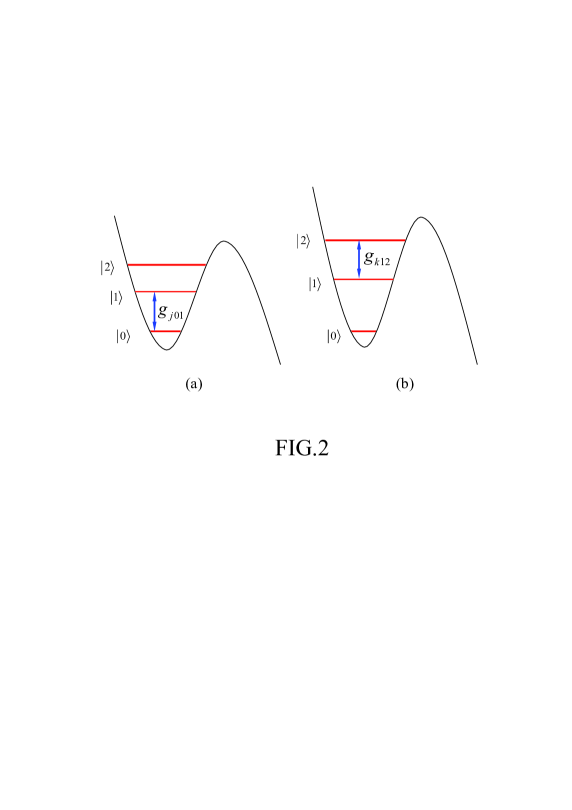
A.2 Implementing a two-qubit CP gate— We define () as the resonant coupling constant between the cavity mode and the () transition of qutrit (). The cavity is initially in the vacuum state The procedure for realizing is listed as follows:
Step (i). Adjust the level spacings of qutrit such that the transition is on resonance with the cavity [Fig. 2(a)]. After an interaction time , the state changes to while nothing happens to the state (e.g., see [19]).
Step (ii). Adjust the level spacings of qutrit such that the transition is on resonance with the cavity [Fig. 2(b)]. After an interaction time the state becomes while the states and remain unchanged.
Step (iii). Adjust the level spacings of qutrit such that the transition is on resonance with the cavity [Fig. 2(a)]. After an interaction time , the state changes to while nothing happens to the state
One can check that the state remains unchanged while the state changes to after the above operations. On the other hand, the initial states {} remain unchanged during the entire operation above. These results show that a two-qubit CP gate described by Eq. (2), was achieved with qutrit (the control) and qutrit (the target) after the above process, while the cavity returns to its original vacuum state.
A.3 Realizing a two-target-qubit CP gate— By carefully examining the procedure described above for implementing , we note that a two-targe-qubit CP gate described by Eq. (3) can be realized using four operational steps only:
Steps (i) and (ii): the operations for these two steps are the same as those for steps (i) and (ii) described above.
Step (iii): Adjust the level spacings of qutrit such that the transition is on resonance with the cavity. After an interaction time (where is the coupling constant between the cavity mode and the transition of qutrit ), the state becomes while the states and remain unchanged.
Step (iv): the operation for this step is the same as that for step (iii).
During performing single-qubit-gate operations, all three superconducting phase qutrits and need to be decoupled from the cavity mode; and during performing a two-qubit CP gate or a two-target-qubit CP gate, irrelevant qutrits need to be decoupled from the cavity mode. This requirement can be met by a prior adjustment of the level spacings of the qutrits. Note that for superconducting qutrits, the level spacings can be rapidly adjusted by varying external control parameters (e.g., magnetic flux applied to phase, transmon, or flux qutrits; see, e.g., [3,36,37]).
As a final note, it should be mentioned that the method described above for implementing a two-qubit CP gate via resonant interaction is not new, which was previously proposed [38,39]. We would like to stress that our focus is to take the resonant interaction as an example to explore the possibility of implementing the three-qubit DJ algorithm with superconducting transmon qutrits coupled to a single cavity, by using the protocol presented in the previous section.
IV.2 Fidelity
Let us now study the fidelity of the operation. Since the resonant interaction is used in the implementation of the single-qubit gates or gates, these basic gates can be completed within a very short time (e.g., by increasing the pulse Rabi frequency). In addition, as mentioned previously, one can apply the DRAG pulses to eliminate the leakage into the level Thus, the single-qubit gate error is negligibly small. In this case, decoherence of the system would have a negative impact on the operation of implementing a two-qubit CP gate as well as a two-target-qubit CP gate, due to the population of the cavity photons during the operation. As discussed above, the implementation of these CP gates involves two basic operations:
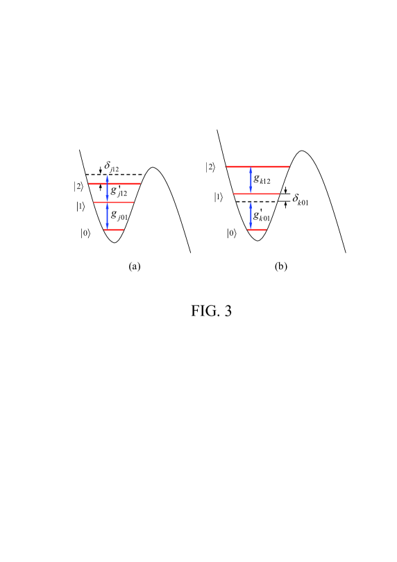
(i) The first one requires that during performing and the cavity mode is resonant with the transition of the control qutrit In realistic case, the interaction Hamiltonian for this basic operation is given by
| (5) |
where is the photon creation operator of the cavity mode, and the second term represents the unwanted off-resonant coupling between the cavity mode and the transition, with a coupling constant and a detuning [Fig. 3(a)].
(ii) The second one requires that during performing and the cavity mode is resonant with the transition of the target qutrit The interaction Hamiltonian for this basic operation is given by
| (6) |
where the second term represents the unwanted off-resonant coupling between the cavity mode and the transition, with a coupling constant and a detuning [Fig. 3(b)].
As discussed previously, the cavity mode needs to be resonant with the transition of the target qutrit during performing Note that the Hamiltonian governing this basic operation is the same as with a replacement of the index by
It should be mentioned that the term describing the pulse-induced or the cavity-induced coherent transition for each qutrit is not included in the Hamiltonians and , since this transition is negligible because of () (Fig. 3).
For each of the two basic types of operations described above, the dynamics of the lossy system, composed of three qutrits () and the cavity, is determined by
| (7) | |||||
where is the or above, represents qutrit (), with . In addition, is the decay rate of the cavity mode, and are, respectively, the energy relaxation rates of the level of qutrit for the decay paths , , and and () is the dephasing rate of the level () of qutrit .
The fidelity of the operation is given by [40]
| (8) |
where is the output state of an ideal system (i.e., without dissipation and dephasing) after a joint operation or is performed on the qutrit system initially in the state and the cavity mode initially in the vacuum state , which is given by
| (9) |
while is the final density operator of the whole system when the gate operations are performed in a realistic physical system.
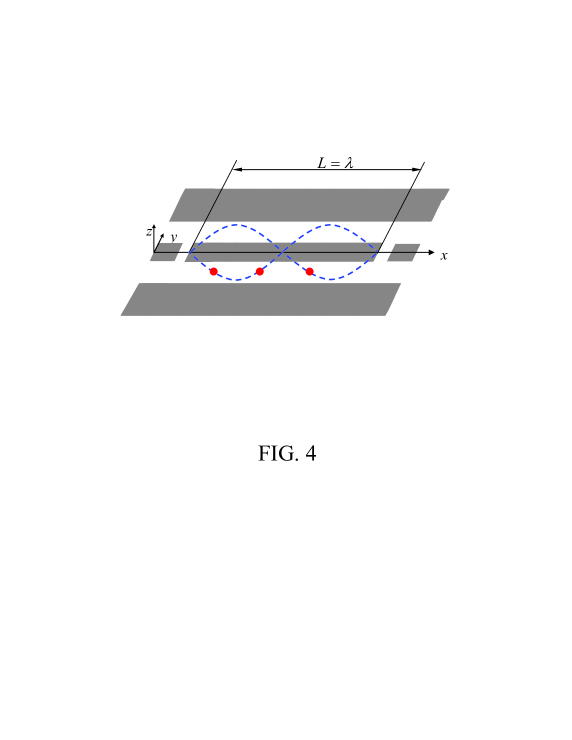
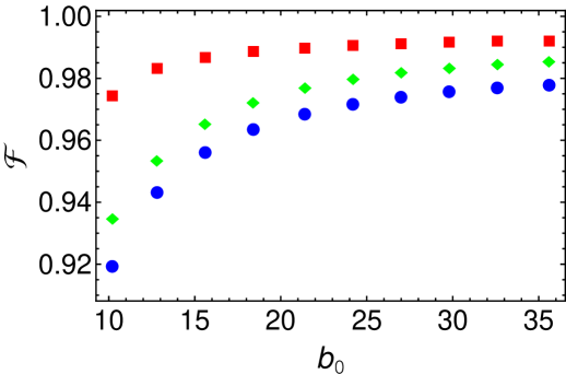
We now numerically calculate the fidelity of the joint operations and , for a setup shown in Fig. 4. Without loss of generality, let us consider three identical transmon qutrits. In this case, we can drop off the first subscript () for the detunings, Rabi frequencies, and coupling constants. For simplicity, we assume that One has for the transmon qutrit here [41]. Choose MHz, which can be reached for a superconducting transmon qutrit coupled to a one-dimensional standing-wave CPW (coplanar waveguide) resonator [42]. Other parameters used in the numerical calculation are as follows: s, s, s [43], s, and s. Define and . For simplicity, we choose For the parameters chosen above, the fidelity versus is shown in Fig. 5, from which one can see that for a high fidelity and can be achieved for the joint operations and respectively. We remark that the fidelity can be further increased by improving system parameters.
For and we have GHz, GHz, which is achieved in experiments [44]. and can be made to be on the order of s for state-of-the-art superconducting transom devices [4]. For superconducting transmon qutrits, the typical transition frequency between two neighbor levels is between 4 and 10 GHz [6,21,23,24]. As an example, let us consider a cavity with frequency GHz. Thus, for the used in the numerical calculation, the required quality factor for the cavity is . Note that superconducting CPW resonators with a loaded quality factor have been experimentally demonstrated [45,46], and planar superconducting resonators with internal quality factors above one million () have also been reported recently [47]. Our analysis given here demonstrates that implementation of the three-qubit refined DJ algorithm is feasible within the present circuit QED technique.
V CONCLUSION
We have proposed a protocol for constructing the 35 -controlled phase gates of a three-qubit refined DJ algorithm, by using single-qubit gates, two-qubit CP gates and two-target-qubit CP gates. Using this protocol, we have discussed how to implement the three-qubit refined DJ algorithm with superconducting transmon qutrits resonantly coupled to a cavity. Our numerical calculation shows that implementation of this quantum algorithm is feasible for the current circuit QED. Finally, it is noted that this protocol is quite general and can be applied to implement the three-qubit refined Deutsch-Jozsa algorithm in various of physical systems.
ACKNOWLEDGMENTS
C.P.Y. was supported in part by the National Natural Science Foundation of China under Grant Nos. 11074062 and 11374083, the Zhejiang Natural Science Foundation under Grant No. LZ13A040002, and the funds from Hangzhou Normal University under Grant Nos. HSQK0081 and PD13002004. Q.P.S. was supported by the Zhejiang Provincial Natural Science Foundation of China under Grant No. LQ12A05004. This work was also supported by the funds from Hangzhou City for the Hangzhou-City Quantum Information and Quantum Optics Innovation Research Team.
References
- (1) A. Blais, R. S. Huang, A. Wallraff, S. M. Girvin, and R. J. Schoelkopf, Cavity quantum electrodynamics for superconducting electrical circuits: An architecture for quantum computation, Phys. Rev. A 69, 062320 (2004).
- (2) J. Q. You and F. Nori, Atomic physics and quantum optics using superconducting circuits,Nature (London) 474, 589 (2011); P. D. Nation, J. R. Johansson, M. P. Blencowe, and F. Nori, Colloquium: Stimulating uncertainty: Amplifying the quantum vacuum with superconducting circuits, Rev. Mod. Phys. 84, 1 (2012); Z. L. Xiang, S. Ashhab, J. Q. You, and F. Nori, Hybrid quantum circuits: Superconducting circuits interacting with other quantum systems, Rev. Mod. Phys. 85, 623 (2013).
- (3) J. Clarke and F. K. Wilhelm, Superconducting quantum bits, Nature (London) 453, 1031 (2008).
- (4) J. B. Chang et al., Improved superconducting qubit coherence using titanium nitride, Appl. Phys. Lett. 103, 012602 (2013); H. Paik et al., Observation of High Coherence in Josephson Junction Qubits Measured in a Three-Dimensional Circuit QED Architecture, Phys. Rev. Lett. 107, 240501 (2011); J. M. Chow et al., Implementing a strand of a scalable fault-tolerant quantum computing fabric, Nature Communications 5, 4015 (2014).
- (5) C. P. Yang, S. I. Chu and S. Han, Possible realization of entanglement, logical gates, and quantum-information transfer with superconducting-quantum-interference-device qubits in cavity QED, Phys. Rev. A 67, 042311 (2003).
- (6) J. Majer et al., Coupling superconducting qubits via a cavity bus, Nature (London) 449, 443 (2007).
- (7) L. DiCarlo et al., Demonstration of two-qubit algorithms with a superconducting quantum processor, Nature (London) 460, 240 (2009).
- (8) C. P. Yang, S. I. Chu and S. Han, Quantum Information Transfer and Entanglement with SQUID Qubits in Cavity QED: A Dark-State Scheme with Tolerance for Nonuniform Device Parameter, Phys. Rev. Lett. 92, 117902 (2004).
- (9) I. Chiorescu et al., Coherent dynamics of a flux qubit coupled to a harmonic oscillator, Nature (London) 431, 159 (2004).
- (10) A. Wallraff et al., Strong coupling of a single photon to a superconducting qubit using circuit quantum electrodynamics, Nature (London) 431, 162 (2004).
- (11) J. Q. You and F. Nori, Quantum information processing with superconducting qubits in a microwave field, Phys. Rev. B 68, 064509 (2003).
- (12) C. P. Yang, S. I. Chu and S. Han, Simplified realization of two-qubit quantum phase gate with four-level systems in cavity QED, Phys. Rev. A 70, 044303 (2004); J. of Phys.: Cond. Mat. 16, 1907 (2004); X. L. He et al., Quantum logical gates with four-level superconducting quantum interference devices coupled to a superconducting resonator, Phys. Rev. A 82, 024301 (2010).
- (13) P. Zhang, Z. D. Wang, J. D. Sun, and C. P. Sun, Holonomic quantum computation using rf superconducting quantum interference devices coupled through a microwave cavity, Phys. Rev. A 71, 042301 (2005).
- (14) S. L. Zhu, Z. D. Wang, and P. Zanardi, Geometric Quantum Computation and Multiqubit Entanglement with Superconducting Qubits inside a Cavity, Phys. Rev. Lett. 94, 100502 (2005).
- (15) K. H. Song, Z. W. Zhou, and G. C. Guo, Quantum logic gate operation and entanglement with superconducting quantum interference devices in a cavity via a Raman transition, Phys. Rev. A 71, 052310 (2005).
- (16) Z. B. Feng, Coupling charge qubits via Raman transitions in circuit QED, Phys. Rev. A 78, 032325 (2008).
- (17) S. Saito, T. Tilma, S. J. Devitt, K. Nemoto, and K. Semba, Experimentally realizable controlled NOT gate in a flux qubit/resonator system, Phys. Rev. B 80, 224509 (2009).
- (18) G. Haak, F. Helmer, M. Mariantona, F. Marquardt, and E. Solano, Resonant quantum gates in circuit quantum electrodynamics, Phys. Rev. B. 82, 024514 (2010).
- (19) C. P. Yang and S. Han, n-qubit-controlled phase gate with superconducting quantum-interference devices coupled to a resonator, Phys. Rev. A 72, 032311 (2005); 73, 032317 (2006).
- (20) C. P. Yang, Y. X. Liu, and F. Nori, Phase gate of one qubit simultaneously controlling n qubits in a cavity, Phys. Rev. A 81, 062323 (2010); C. P. Yang, S. B. Zheng, and F. Nori, Multiqubit tunable phase gate of one qubit simultaneously controlling n qubits in a cavity, Phys. Rev. A 82, 062326 (2010).
- (21) P. J. Leek, S. Filipp, P. Maurer, M. Baur, R. Bianchetti, J. M. Fink, M. Goppl, L. Steffen, and A. Wallraff, Using sideband transitions for two-qubit operations in superconducting circuits, Phys. Rev. B 79, 180511(R) (2009).
- (22) E. Lucero et al., Computing prime factors with a Josephson phase qubit quantum processor, arXiv:1202.5707.
- (23) A. Fedorov, L. Steffen, M. Baur, M. P. daSilva, and A. Wallraff, Implementation of a Toffoli gate with superconducting circuits, Nature (London) 481, 170 (2012).
- (24) M. D. Reed et al., Realization of three-qubit quantum error correction with superconducting circuits, Nature (London) 482, 382 (2012).
- (25) M. Mariantoni et al., Implementing the Quantum von Neumann Architecture with Superconducting Circuits, Science 334, 61 (2011).
- (26) P. W. Shor, Algorithms for quantum computation: discrete logarithms and factoring, in Proceedings of the 35th Annual Symposium on Foundation of Computer Science (IEEE Computer Society, Los Alamos, CA, 1994), p. 124.
- (27) L. K. Grover, Quantum Mechanics Helps in Searching for a Needle in a Haystack, Phys. Rev. Lett. 79, 325 (1997).
- (28) D. Deutsch, Quantum Theory, the Church-Turing Principle and the Universal Quantum Computer, Proc. R. Soc. London Scr. A 400, 97 (1985); D. Deutsch, Quantum Computational Networks, Proc. R. Soc. London Scr. A 425, 73 (1989).
- (29) D. Deutsch and R. Jozsa, Rapid Solution of Problems by Quantum Computation, Proc. R. Soc. London Scr. A 439, 553 (1992).
- (30) P. Shor, Polynomial-Time Algorithms for Prime Factorization and Discrete Logarithms on a Quantum Computer, SIAM J. Comput. 26, 1484 (1997).
- (31) D. Simon, On the power of quantum computation, Proc. 35th Annual Symposium on Foundations of Computer Science, IEEE Computer Society Press, Los Alamitos, CA, 116 (1994).
- (32) L. Grover, A Fast Quantum Mechanical Algorithm for Database Search, Proc. 28th Annual ACM Symposium on Theory of Computing, ACM Press, New York, 212 (1996).
- (33) D. Collins, K. W. Kim, and W. C. Holton, Deutsch-Jozsa algorithm as a test of quantum computation, Phys. Rev. A 58, 1633(R) (1998).
- (34) F. Motzoi, J. M. Gambetta, P. Rebentrost, and F. K. Wilhelm, Simple Pulses for Elimination of Leakage in Weakly Nonlinear Qubits, Phys. Rev. Lett. 103, 110501 (2009).
- (35) Erik Lucero et al., Reduced phase error through optimized control of a superconducting qubit, Phys. Rev. A 82, 042339 (2010).
- (36) S. Han, J. Lapointe, and J. E. Lukens, in Single-Electron Tunneling and Mesoscopic Devices, Springer Series in Electronics and Photonics, Vol. 31 (Springer, Berlin, 1991), pp. .
- (37) M. Neeley, M. Ansmann, R. C. Bialczak, M. Hofheinz, N. Katz, E. Lucero, A. OConnell, H. Wang, A. N. Cleland, and J. M. Martinis, Process tomography of quantum memory in a Josephson-phase qubit coupled to a two-level state, Nature Phys. 4, 523 (2008).
- (38) A. Rauschenbeutel, G. Nogues, S. Osnaghi, P. Bertet, M. Brune, J. M. Raimond, and S. Haroche, Coherent operation of a tunable quantum phase gate in cavity QED, Phys. Rev. Lett. 83, 5166 (1999).
- (39) M. S. Sherwin, A. Imamoglu, and T. Montroy, Quantum computation with quantum dots and terahertz cavity quantum electrodynamics, Phys. Rev. A 60, 3508 (1999).
- (40) M. A. Nielsen and I. L. Chuang, Quantum Computation and Quantum Information (Cambridge University Press, Cambridge, England, 2001).
- (41) J. Koch, T. M. Yu, J. Gambetta, A. A. Houck, D. I. Schuster, J. Majer, A. Blais, M. H. Devoret, S. M. Girvin, and R. J. Schoelkopf, Charge-insensitive qubit design derived from the Cooper pair box, Phys. Rev. A 76, 042319 (2007).
- (42) L. DiCarlo, M. D. Reed, L. Sun, B. R. Johnson, J. M. Chow, J. M. Gambetta, L. Frunzio, S. M. Girvin, M. H. Devoret, and R. J. Schoelkopf, Preparation and measurement of three-qubit entanglement in a superconducting circuit, Nature (London) 467, 574 (2010).
- (43) For a transmon qutrit with the three levels considered, the dipole matrix element is much smaller than that of the and transitions (see [38]). Thus,
- (44) J. A. Schreier et al., Suppressing charge noise decoherence in superconducting charge qubits, Phys. Rev. B 77, 180502(R) (2008).
- (45) W. Chen, D. A. Bennett, V. Patel, and J. E. Lukens, Substrate and process dependent losses in superconducting thin film resonators, Supercond. Sci. Technol. 21, 075013 (2008).
- (46) P. J. Leek, M. Baur, J. M. Fink, R. Bianchetti, L. Steffen, S. Filipp, and A. Wallraff, Cavity Quantum Electrodynamics with Separate Photon Storage and Qubit Readout Modes, Phys. Rev. Lett. 104, 100504 (2010).
- (47) A. Megrant et al., Planar superconducting resonators with internal quality factors above one million, Appl. Phys. Lett. 100, 113510 (2012).